

User Manual
Page 3
Contents Notices...vi Safety information vii About this guide vii P8P67 LX specifications summary ix Chapter 1 Product introduction 1.1 Welcome 1-1 1.2 Package contents 1-1 1.3 Special features 1-1 1.3.1 Product highlights 1-1 1.3.2 Innovative ASUS features 1-3 1.4 Before you proceed 1-6 1.5 Motherboard overview 1-7 1.5.1 Placement direction 1-7 1.5.2 Screw holes 1-7 1.5.3 Motherboard layout 1-8 1.5.4 Layout contents 1-8 1.6 Central Processing Unit (CPU 1-9 1.6.1 Installing the CPU 1-9 1.6.2 Installing the CPU heatsink and fan 1-12...
Contents Notices...vi Safety information vii About this guide vii P8P67 LX specifications summary ix Chapter 1 Product introduction 1.1 Welcome 1-1 1.2 Package contents 1-1 1.3 Special features 1-1 1.3.1 Product highlights 1-1 1.3.2 Innovative ASUS features 1-3 1.4 Before you proceed 1-6 1.5 Motherboard overview 1-7 1.5.1 Placement direction 1-7 1.5.2 Screw holes 1-7 1.5.3 Motherboard layout 1-8 1.5.4 Layout contents 1-8 1.6 Central Processing Unit (CPU 1-9 1.6.1 Installing the CPU 1-9 1.6.2 Installing the CPU heatsink and fan 1-12...

User Manual
Page 18
Doing so can cause you physical injury and damage motherboard components. 1.5.1 Placement direction When installing the motherboard, ensure that you place it . Place this side towards the rear of the chassis P8P67 LX 1-7 Chapter 1: Product introduction The edge with external ports goes to the rear part of the chassis as indicated in the image...
Doing so can cause you physical injury and damage motherboard components. 1.5.1 Placement direction When installing the motherboard, ensure that you place it . Place this side towards the rear of the chassis P8P67 LX 1-7 Chapter 1: Product introduction The edge with external ports goes to the rear part of the chassis as indicated in the image...

User Manual
Page 21
... the tab only. DO NOT force the CPU into the CPU notches. Load plate 4. Gold triangle mark Alignment keys CPU notches ASUS P8P67 LX 1-10 PnP cap 5. The CPU fits in the direction of the arrow until the load plate is on the bottom‑left corner of the socket, and then fit the...
... the tab only. DO NOT force the CPU into the CPU notches. Load plate 4. Gold triangle mark Alignment keys CPU notches ASUS P8P67 LX 1-10 PnP cap 5. The CPU fits in the direction of the arrow until the load plate is on the bottom‑left corner of the socket, and then fit the...
User Manual
Page 23
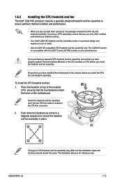
If you purchased a separate CPU heatsink and fan assembly, ensure that you use only Intel®‑certified multi‑directional heatsink and fan. • Your Intel® LGA1155 heatsink and fan assembly comes in a push-pin design and requires no tool to ... Use an LGA1155-compatible CPU heatsink and fan assembly only. Push down two fasteners at a time in a diagonal sequence to the CPU fan connector. 2. ASUS P8P67 LX 1-12 B B Orient the heatsink and fan assembly A such that the CPU fan cable is for reference only. The LGA1155 socket is incompatible with the ...
If you purchased a separate CPU heatsink and fan assembly, ensure that you use only Intel®‑certified multi‑directional heatsink and fan. • Your Intel® LGA1155 heatsink and fan assembly comes in a push-pin design and requires no tool to ... Use an LGA1155-compatible CPU heatsink and fan assembly only. Push down two fasteners at a time in a diagonal sequence to the CPU fan connector. 2. ASUS P8P67 LX 1-12 B B Orient the heatsink and fan assembly A such that the CPU fan cable is for reference only. The LGA1155 socket is incompatible with the ...

User Manual
Page 32
... retaining clips outward to avoid damaging the DIMM. 3. Remove the DIMM from the socket. The DIMM might get damaged when it fits in the wrong direction to unlock the DIMM. 2 Support the DIMM lightly with a notch so that the notch on the DIMM matches the DIMM slot key on the socket... out with extra force. 1 2. Failure to do so can cause severe damage to unlock a DIMM socket. 2. Firmly insert the DIMM into a socket in only one direction. Locked Retaining Clip 1.7.4 Removing a DIMM To remove a DIMM: 1.
... retaining clips outward to avoid damaging the DIMM. 3. Remove the DIMM from the socket. The DIMM might get damaged when it fits in the wrong direction to unlock the DIMM. 2 Support the DIMM lightly with a notch so that the notch on the DIMM matches the DIMM slot key on the socket... out with extra force. 1 2. Failure to do so can cause severe damage to unlock a DIMM socket. 2. Firmly insert the DIMM into a socket in only one direction. Locked Retaining Clip 1.7.4 Removing a DIMM To remove a DIMM: 1.

User Manual
Page 77
... product Product Name : Motherboard Model Number : P8P67 LX Conforms to the following directives: 2004/108/EC-EMC Directive EN 55022:2006+A1:2007 EN 61000-3-2:2006 EN 55013:2001+A1:2003+A2:2006 1999/5/EC-R &TTE Directive EN 300 328 V1.7.1(2006-05) EN 300...may cause undesired operation. Country: TAIWAN Authorized representative in Europe: ASUS COMPUTER GmbH Address, City: HARKORT STR. 21-23, 40880 RATINGEN Country: GERMANY declare the following apparatus: Product name : Motherboard Model name : P8P67 LX conform with the essential requirements of the following specifications: FCC ...
... product Product Name : Motherboard Model Number : P8P67 LX Conforms to the following directives: 2004/108/EC-EMC Directive EN 55022:2006+A1:2007 EN 61000-3-2:2006 EN 55013:2001+A1:2003+A2:2006 1999/5/EC-R &TTE Directive EN 300 328 V1.7.1(2006-05) EN 300...may cause undesired operation. Country: TAIWAN Authorized representative in Europe: ASUS COMPUTER GmbH Address, City: HARKORT STR. 21-23, 40880 RATINGEN Country: GERMANY declare the following apparatus: Product name : Motherboard Model name : P8P67 LX conform with the essential requirements of the following specifications: FCC ...