
P8H77-I User's Manual
Page 10
P8H77-I specifications summary Internal I/O Connector BIOS Manageability Accessories Support DVD Form Factor 1 x USB... 1 x System Panel connector 1 x 24-pin ATX Power connector 1 x 4-pin ATX 12V Power connector 1 x S/PDIF Out connector 1 x Clear CMOS jumper(s) 1 x Speaker header 64 Mb Flash ROM, AMI BIOS, PnP, DMI2.0, WfM2.0, SM BIOS 2.5, ACPI 2.0a WOL by PME, PXE ...2 x Serial ATA 6.0Gb/s cables 1 x I/O Shield 1 x User's manual 1 x Support DVD Drivers ASUS Utilities ASUS Update Anti-virus software (OEM version) Mini-ITX Form Factor, 6.7"x 6.7" (17.0cm x 17.0cm) * Specifications are subject ...
P8H77-I specifications summary Internal I/O Connector BIOS Manageability Accessories Support DVD Form Factor 1 x USB... 1 x System Panel connector 1 x 24-pin ATX Power connector 1 x 4-pin ATX 12V Power connector 1 x S/PDIF Out connector 1 x Clear CMOS jumper(s) 1 x Speaker header 64 Mb Flash ROM, AMI BIOS, PnP, DMI2.0, WfM2.0, SM BIOS 2.5, ACPI 2.0a WOL by PME, PXE ...2 x Serial ATA 6.0Gb/s cables 1 x I/O Shield 1 x User's manual 1 x Support DVD Drivers ASUS Utilities ASUS Update Anti-virus software (OEM version) Mini-ITX Form Factor, 6.7"x 6.7" (17.0cm x 17.0cm) * Specifications are subject ...
P8H77-I User's Manual
Page 18
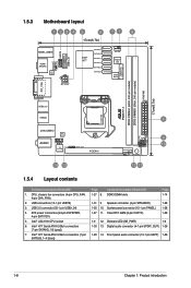
...connector (4-pin SPEAKER) 1-28 1-30 10. ATX power connectors (24-pin EATXPWR, 4-pin EATX12V) 5. Clear RTC RAM (3-pin CLRTC) 1-28 1-9 12. Front panel audio connector (10-1 pin AAFP) 1-26 ... USB78 USB3_34 1.5.3 Motherboard layout 1234 5 6 71 8 17cm(6.7in) Lithium Cell CMOS Power KBMS_USB56 HDMI SPDIFO CPU_FAN ASM 1442 ATX12V Intel® H77 SATA6G_1 SATA6G_2 SATA3G_1 ...module) USB3_12 USB34 LAN_USB12 RTL 8111F AUDIO AAFP VIA VT1708S SPDIF_OUT PCIEX16 14 13 LGA1155 P8H77-I CLRTC SPEAKER F_PANEL 4 9 10 SB_PWR 12 11 1.5.4 Layout contents Connectors/Jumpers/Slots...
...connector (4-pin SPEAKER) 1-28 1-30 10. ATX power connectors (24-pin EATXPWR, 4-pin EATX12V) 5. Clear RTC RAM (3-pin CLRTC) 1-28 1-9 12. Front panel audio connector (10-1 pin AAFP) 1-26 ... USB78 USB3_34 1.5.3 Motherboard layout 1234 5 6 71 8 17cm(6.7in) Lithium Cell CMOS Power KBMS_USB56 HDMI SPDIFO CPU_FAN ASM 1442 ATX12V Intel® H77 SATA6G_1 SATA6G_2 SATA3G_1 ...module) USB3_12 USB34 LAN_USB12 RTL 8111F AUDIO AAFP VIA VT1708S SPDIF_OUT PCIEX16 14 13 LGA1155 P8H77-I CLRTC SPEAKER F_PANEL 4 9 10 SB_PWR 12 11 1.5.4 Layout contents Connectors/Jumpers/Slots...
P8H77-I User's Manual
Page 33
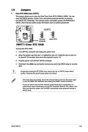
... 23 Normal (Default) P8H77-I 1-23 Shut down the key during the boot process and enter BIOS setup to pins 1-2. 3. Move the jumper cap from pins 1-2 (default) to clear the CMOS RTC RAM data. Plug the power cord and turn ON the computer. 4. Removing the cap will cause system.... For system failure due to clear the Real Time Clock (RTC) RAM in CMOS, which include system setup information such as system passwords. Turn OFF the computer and unplug the power cord. 2. Keep the cap on CLRTC jumper default position. ASUS P8H77-I Clear RTC RAM Clear RTC To erase the RTC RAM...
... 23 Normal (Default) P8H77-I 1-23 Shut down the key during the boot process and enter BIOS setup to pins 1-2. 3. Move the jumper cap from pins 1-2 (default) to clear the CMOS RTC RAM data. Plug the power cord and turn ON the computer. 4. Removing the cap will cause system.... For system failure due to clear the Real Time Clock (RTC) RAM in CMOS, which include system setup information such as system passwords. Turn OFF the computer and unplug the power cord. 2. Keep the cap on CLRTC jumper default position. ASUS P8H77-I Clear RTC RAM Clear RTC To erase the RTC RAM...
P8H77-I User's Manual
Page 49
... after changing any BIOS setting, try to clear the CMOS and reset the motherboard to the default value. Using the power button, reset button, or the ++ keys to force reset from the operating system. • The BIOS setup screens shown in using the first two options. ASUS P8H77-I 2-7 2.2 BIOS setup program Use the BIOS...
... after changing any BIOS setting, try to clear the CMOS and reset the motherboard to the default value. Using the power button, reset button, or the ++ keys to force reset from the operating system. • The BIOS setup screens shown in using the first two options. ASUS P8H77-I 2-7 2.2 BIOS setup program Use the BIOS...
P8H77-I User's Manual
Page 53
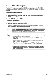
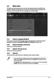
EFI BIOS Utility - After you set a password, these items show the default Not Installed. ASUS P8H77-I 2-11 See section 1.9 Jumpers for information on how to erase the RTC RAM. • The Administrator or User Password items on top of the screen .../2010] [16:46:15] Administrator > Security Boot Tool Choose the system default language 2.3.1 System Language [English] Allows you have forgotten your BIOS password, erase the CMOS Real Time Clock (RTC) RAM to clear the BIOS password. The Main menu provides you an overview of the BIOS Setup program.
EFI BIOS Utility - After you set a password, these items show the default Not Installed. ASUS P8H77-I 2-11 See section 1.9 Jumpers for information on how to erase the RTC RAM. • The Administrator or User Password items on top of the screen .../2010] [16:46:15] Administrator > Security Boot Tool Choose the system default language 2.3.1 System Language [English] Allows you have forgotten your BIOS password, erase the CMOS Real Time Clock (RTC) RAM to clear the BIOS password. The Main menu provides you an overview of the BIOS Setup program.


