
User Manual
Page 4
... and updating your BIOS 2-1 2.1.1 ASUS Update utility 2-1 2.1.2 ASUS EZ Flash 2 2-2 2.1.3 ASUS CrashFree BIOS 3 utility 2-3 2.1.4 ASUS BIOS Updater 2-4 2.2 BIOS setup ...program 2-7 2.3 Main menu 2-11 2.3.1 System Language 2-11 2.3.2 System Date 2-11 2.3.3 System Time 2-11 2.3.4 Security 2-11 2.4 Ai Tweaker menu 2-13 2.4.1 Ai Overclock Tuner 2-13 2.4.2 Memory Frequency 2-14 2.4.3 EPU Power Saving Mode 2-14 2.4.4 GPU Boost 2-14 2.4.5 DRAM Timing Control 2-14 2.4.6 CPU Power...
... and updating your BIOS 2-1 2.1.1 ASUS Update utility 2-1 2.1.2 ASUS EZ Flash 2 2-2 2.1.3 ASUS CrashFree BIOS 3 utility 2-3 2.1.4 ASUS BIOS Updater 2-4 2.2 BIOS setup ...program 2-7 2.3 Main menu 2-11 2.3.1 System Language 2-11 2.3.2 System Date 2-11 2.3.3 System Time 2-11 2.3.4 Security 2-11 2.4 Ai Tweaker menu 2-13 2.4.1 Ai Overclock Tuner 2-13 2.4.2 Memory Frequency 2-14 2.4.3 EPU Power Saving Mode 2-14 2.4.4 GPU Boost 2-14 2.4.5 DRAM Timing Control 2-14 2.4.6 CPU Power...

User Manual
Page 7
...information you need when installing and configuring the motherboard. vii These devices could interrupt the grounding circuit. • Ensure that your power supply is organized This guide contains the following parts: • Chapter 1: Product introduction This chapter describes the features of the ...devices to or from connectors, slots, sockets and circuitry. • Avoid dust, humidity, and temperature extremes. If possible, disconnect all power cables from the existing system before the signal cables are also provided. If you detect any area where it by yourself. Contact a ...
...information you need when installing and configuring the motherboard. vii These devices could interrupt the grounding circuit. • Ensure that your power supply is organized This guide contains the following parts: • Chapter 1: Product introduction This chapter describes the features of the ...devices to or from connectors, slots, sockets and circuitry. • Avoid dust, humidity, and temperature extremes. If possible, disconnect all power cables from the existing system before the signal cables are also provided. If you detect any area where it by yourself. Contact a ...

User Manual
Page 10
P8H67-M specifications summary Audio USB ASUS Special features Internal connectors ALC887-VD 8-channel* High Definition Audio CODEC supports - MemOK! ASUS O.C. Profile - ASUS EZ Flash 2 - Intel&#...ASUS MyLogo 2 4 x USB 2.0/1.1 connectors support additional 8 USB 2.0/1.1 ports 1 x IDE connector 1 x System panel connector 1 x S/PDIF Out connector 4 x SATA 3.0 Gb/s connectors 2 x SATA 6.0 Gb/s connectors 1 x Front panel audio connector 1 x CPU fan connector 1 x Chassis fan connector 1 x COM connector 1 X LPT connector 1 x TPM connector 1 x 24-pin EATX Power connector 1 x 8-pin EATX 12V Power...
P8H67-M specifications summary Audio USB ASUS Special features Internal connectors ALC887-VD 8-channel* High Definition Audio CODEC supports - MemOK! ASUS O.C. Profile - ASUS EZ Flash 2 - Intel&#...ASUS MyLogo 2 4 x USB 2.0/1.1 connectors support additional 8 USB 2.0/1.1 ports 1 x IDE connector 1 x System panel connector 1 x S/PDIF Out connector 4 x SATA 3.0 Gb/s connectors 2 x SATA 6.0 Gb/s connectors 1 x Front panel audio connector 1 x CPU fan connector 1 x Chassis fan connector 1 x COM connector 1 X LPT connector 1 x TPM connector 1 x 24-pin EATX Power connector 1 x 8-pin EATX 12V Power...
User Manual
Page 13
... missing, contact your retailer. 1.3 1.3.1 Special features Product highlights LGA1155 socket for buying an ASUS® P8H67-M motherboard! ASUS P8H67-M 1-1 Chapter 1 Product introduction 1.1 Welcome! The motherboard delivers a host of new features ...ASUS P8H67-M motherboard 2 x Serial ATA 6.0Gb/s cables 1 x Ultra DMA 133/100 cable 1 x I/O shield ASUS motherboard support DVD User Manual If any of ASUS quality motherboards! This provides great graphics performance. Intel® Second Generation Core™ i7/ Core™ i5/ Core™ i3 processors are among the most powerful...
... missing, contact your retailer. 1.3 1.3.1 Special features Product highlights LGA1155 socket for buying an ASUS® P8H67-M motherboard! ASUS P8H67-M 1-1 Chapter 1 Product introduction 1.1 Welcome! The motherboard delivers a host of new features ...ASUS P8H67-M motherboard 2 x Serial ATA 6.0Gb/s cables 1 x Ultra DMA 133/100 cable 1 x I/O shield ASUS motherboard support DVD User Manual If any of ASUS quality motherboards! This provides great graphics performance. Intel® Second Generation Core™ i7/ Core™ i5/ Core™ i3 processors are among the most powerful...
User Manual
Page 14
... supports DDR3 memory that features data transfer rates of 1333 / 1066 MHz to meet the higher bandwidth requirements of your system memory to provide efficient power management for advanced operating systems. 100% All High-quality Conductive Polymer Capacitors This motherboard uses all high-quality conductive polymer capacitors for double speed and...
... supports DDR3 memory that features data transfer rates of 1333 / 1066 MHz to meet the higher bandwidth requirements of your system memory to provide efficient power management for advanced operating systems. 100% All High-quality Conductive Polymer Capacitors This motherboard uses all high-quality conductive polymer capacitors for double speed and...
User Manual
Page 15
...Auto Tuning Auto Tuning is for the best graphics performance. Even O.C. ASUS Anti-Surge Protection This special design prevents expensive devices and the motherboard from damage caused by power surges from switching power supply (PSU). All in no need to overclock without exiting or rebooting...software package. You can achieve extreme yet stable overclocking results with no time. User-friendly UI facilitates flexible frequency and voltage adjustments. ASUS P8H67-M 1-3 This remarkable memory rescue tool requires a mere push of real-time OC-now a reality with just a few clicks away...
...Auto Tuning Auto Tuning is for the best graphics performance. Even O.C. ASUS Anti-Surge Protection This special design prevents expensive devices and the motherboard from damage caused by power surges from switching power supply (PSU). All in no need to overclock without exiting or rebooting...software package. You can achieve extreme yet stable overclocking results with no time. User-friendly UI facilitates flexible frequency and voltage adjustments. ASUS P8H67-M 1-3 This remarkable memory rescue tool requires a mere push of real-time OC-now a reality with just a few clicks away...

User Manual
Page 17
... came with the component. • Before you install motherboard components or change any motherboard settings. • Unplug the power cord from the power supply. 1.4 Before you proceed Take note of the following precautions before you install or remove any component, ensure that the ATX... • Before handling components, use a grounded wrist strap or touch a safely grounded object or a metal object, such as the power supply case, to avoid damaging them due to static electricity. • Hold components by the edges to the motherboard, peripherals, or components. ASUS P8H67-M 1-5
... came with the component. • Before you install motherboard components or change any motherboard settings. • Unplug the power cord from the power supply. 1.4 Before you proceed Take note of the following precautions before you install or remove any component, ensure that the ATX... • Before handling components, use a grounded wrist strap or touch a safely grounded object or a metal object, such as the power supply case, to avoid damaging them due to static electricity. • Hold components by the edges to the motherboard, peripherals, or components. ASUS P8H67-M 1-5
User Manual
Page 18
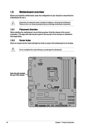
...you physical injury and damage motherboard components. 1.5.1 Placement direction When installing the motherboard, ensure that you place it . Ensure that you unplug the power cord before installing or removing the motherboard. 1.5 Motherboard overview Before you install the motherboard, study the configuration of your chassis to ensure that ...this side towards the rear of the chassis as indicated in the correct orientation. Failure to the rear part of the chassis P8H67-M 1-6 Chapter 1: Product introduction The edge with external ports goes to do so can damage the motherboard.
...you physical injury and damage motherboard components. 1.5.1 Placement direction When installing the motherboard, ensure that you place it . Ensure that you unplug the power cord before installing or removing the motherboard. 1.5 Motherboard overview Before you install the motherboard, study the configuration of your chassis to ensure that ...this side towards the rear of the chassis as indicated in the correct orientation. Failure to the rear part of the chassis P8H67-M 1-6 Chapter 1: Product introduction The edge with external ports goes to do so can damage the motherboard.

User Manual
Page 20
...the socket contacts resulting from the retention tab. Locate the CPU socket on the socket and the socket contacts are installing a CPU. ASUS will process Return Merchandise Authorization (RMA) requests only if the motherboard comes with the cap on the LGA1155 socket. • The ... P8H67-M CPU socket LGA1155 2. 1.6 Central Processing Unit (CPU) The motherboard comes with your retailer immediately if the PnP cap is on the motherboard. Unplug all power cables before installing the CPU. • Upon purchase of the PnP cap. 1.6.1 Installing the CPU To install a CPU: 1. Press the...
...the socket contacts resulting from the retention tab. Locate the CPU socket on the socket and the socket contacts are installing a CPU. ASUS will process Return Merchandise Authorization (RMA) requests only if the motherboard comes with the cap on the LGA1155 socket. • The ... P8H67-M CPU socket LGA1155 2. 1.6 Central Processing Unit (CPU) The motherboard comes with your retailer immediately if the PnP cap is on the motherboard. Unplug all power cables before installing the CPU. • Upon purchase of the PnP cap. 1.6.1 Installing the CPU To install a CPU: 1. Press the...

User Manual
Page 25
... when reinstalling. 1.7 System memory 1.7.1 Overview The motherboard comes with less power consumption. The figure illustrates the location of the DDR3 DIMM sockets: DIMM_A1 DIMM_A2 DIMM_B1 DIMM_B2 P8H67-M Channel Channel A Channel B Sockets DIMM_A1 and DIMM_A2 DIMM_B1 and DIMM_B2 P8H67-M 240-pin DDR3 DIMM sockets ASUS P8H67-M 1-13 Rotate each fastener clockwise to prevent installation on a DDR2...
... when reinstalling. 1.7 System memory 1.7.1 Overview The motherboard comes with less power consumption. The figure illustrates the location of the DDR3 DIMM sockets: DIMM_A1 DIMM_A2 DIMM_B1 DIMM_B2 P8H67-M Channel Channel A Channel B Sockets DIMM_A1 and DIMM_A2 DIMM_B1 and DIMM_B2 P8H67-M 240-pin DDR3 DIMM sockets ASUS P8H67-M 1-13 Rotate each fastener clockwise to prevent installation on a DDR2...

User Manual
Page 30
... the wrong direction to unlock the DIMM. 1 Support the DIMM lightly with extra force. 2. Failure to do so may cause severe damage to unplug the power supply before adding or removing DIMMs or other system components. To install a DIMM 1.
... the wrong direction to unlock the DIMM. 1 Support the DIMM lightly with extra force. 2. Failure to do so may cause severe damage to unplug the power supply before adding or removing DIMMs or other system components. To install a DIMM 1.
User Manual
Page 31
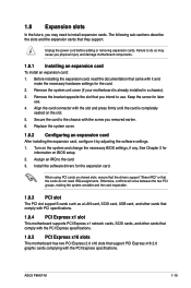
...with the PCI Express specifications. Align the card connector with the screw you may cause you intend to do not need to install expansion cards. ASUS P8H67-M 1-19 See Chapter 2 for the card. 2. Otherwise, conflicts will arise between the two PCI groups, making the system unstable and the...IRQ assignments. Install the software drivers for later use . Failure to use . 4. Secure the card to the card. 3. Unplug the power cord before adding or removing expansion cards. Remove the system unit cover (if your motherboard is completely seated on shared slots, ensure that the...
...with the PCI Express specifications. Align the card connector with the screw you may cause you intend to do not need to install expansion cards. ASUS P8H67-M 1-19 See Chapter 2 for the card. 2. Otherwise, conflicts will arise between the two PCI groups, making the system unstable and the...IRQ assignments. Install the software drivers for later use . Failure to use . 4. Secure the card to the card. 3. Unplug the power cord before adding or removing expansion cards. Remove the system unit cover (if your motherboard is completely seated on shared slots, ensure that the...

User Manual
Page 32
...as system passwords. You can clear the CMOS memory of date, time, and system setup parameters by erasing the CMOS RTC RAM data. P8H67-M CLRTC 12 23 Normal (Default) P8H67-M Clear RTC RAM Clear RTC To erase the RTC RAM: 1. After clearing the CMOS, reinstall the battery. • You do ...the CMOS RTC RAM data. For system failure due to overclocking. Keep the cap on CLRTC jumper default position. The onboard button cell battery powers the RAM data in CMOS. VGA configuration Single VGA/PCIe card Dual VGA/PCIe card PCI Express operating mode PCIe x16_1 x16 (Recommended for ...
...as system passwords. You can clear the CMOS memory of date, time, and system setup parameters by erasing the CMOS RTC RAM data. P8H67-M CLRTC 12 23 Normal (Default) P8H67-M Clear RTC RAM Clear RTC To erase the RTC RAM: 1. After clearing the CMOS, reinstall the battery. • You do ...the CMOS RTC RAM data. For system failure due to overclocking. Keep the cap on CLRTC jumper default position. The onboard button cell battery powers the RAM data in CMOS. VGA configuration Single VGA/PCIe card Dual VGA/PCIe card PCI Express operating mode PCIe x16_1 x16 (Recommended for ...

User Manual
Page 37
...system, we recommend that complies with more power-consuming devices or when you intend to connect the 4-pin / 8-pin ATX +12V power plug. Find the proper orientation and push down firmly until the connectors completely fit. ASUS P8H67-M 1-25 com/PowerSupplyCalculator/PSCalculator.aspx?SLanguage...=en-us for an ATX power supply. 6. Otherwise, the system will not boot up if the power is inadequate. • If you use a PSU with higher power output when configuring a system ...
...system, we recommend that complies with more power-consuming devices or when you intend to connect the 4-pin / 8-pin ATX +12V power plug. Find the proper orientation and push down firmly until the connectors completely fit. ASUS P8H67-M 1-25 com/PowerSupplyCalculator/PSCalculator.aspx?SLanguage...=en-us for an ATX power supply. 6. Otherwise, the system will not boot up if the power is inadequate. • If you use a PSU with higher power output when configuring a system ...

User Manual
Page 40
.... Connect the HDD Activity LED cable to this connector. PWR Ground Reset Ground PANEL PIN 1 P8H67-M IDE_LED PWRSW RESET * Requires an ATX power supply P8H67-M System panel connector • System power LED (2-pin PLED) This 2-pin connector is for the chassis-mounted system warning speaker. The ...speaker allows you turn on the system power, and blinks when the system is in sleep mode. •...
.... Connect the HDD Activity LED cable to this connector. PWR Ground Reset Ground PANEL PIN 1 P8H67-M IDE_LED PWRSW RESET * Requires an ATX power supply P8H67-M System panel connector • System power LED (2-pin PLED) This 2-pin connector is for the chassis-mounted system warning speaker. The ...speaker allows you turn on the system power, and blinks when the system is in sleep mode. •...

User Manual
Page 42
P8H67-M P8H67-M MemOK! Turn off the system and reinstall the DIMM before using the MemOK! If the test fails, the system reboots and test the next set is tested. 1.11 Onboard switches Onboard switches allow you turn off the computer and unplug the power cord for about 30 seconds ... overclockers and gamers who continually change settings to BIOS overclocking, press the MemOK! MemOK! switch to boot after turning on the ASUS website at www.asus.com after using the MemOK! switch lights continuously. If the installed DIMMs still fail to boot and load BIOS default settings. ...
P8H67-M P8H67-M MemOK! Turn off the system and reinstall the DIMM before using the MemOK! If the test fails, the system reboots and test the next set is tested. 1.11 Onboard switches Onboard switches allow you turn off the computer and unplug the power cord for about 30 seconds ... overclockers and gamers who continually change settings to BIOS overclocking, press the MemOK! MemOK! switch to boot after turning on the ASUS website at www.asus.com after using the MemOK! switch lights continuously. If the installed DIMMs still fail to boot and load BIOS default settings. ...

User Manual
Page 43
... problem is a reminder that the system is ON, in sleep mode, or in sequence during motherboard booting process. DRAM LED P8H67-M P8H67-M DRAM LED ASUS P8H67-M 1-31 Standby Power LED The motherboard comes with a standby power LED that lights up to locate the root problem within a second. This user-friendly design provides an intuitional way to...
... problem is a reminder that the system is ON, in sleep mode, or in sequence during motherboard booting process. DRAM LED P8H67-M P8H67-M DRAM LED ASUS P8H67-M 1-31 Standby Power LED The motherboard comes with a standby power LED that lights up to locate the root problem within a second. This user-friendly design provides an intuitional way to...

User Manual
Page 51
...after POST To enter BIOS Setup after POST: • Press ++ simultaneously. • Press the reset button on the system chassis. • Press the power button to turn the system off then back on how to erase the RTC RAM. • The BIOS setup program does not support the bluetooth...ensure system compatibility and stability. If the system becomes unstable after changing any BIOS settings, load the default settings to the default value. Using the power button, reset button, or the ++ keys to force reset from the operating system. • The BIOS setup screens shown in using the first...
...after POST To enter BIOS Setup after POST: • Press ++ simultaneously. • Press the reset button on the system chassis. • Press the power button to turn the system off then back on how to erase the RTC RAM. • The BIOS setup program does not support the bluetooth...ensure system compatibility and stability. If the system becomes unstable after changing any BIOS settings, load the default settings to the default value. Using the power button, reset button, or the ++ keys to force reset from the operating system. • The BIOS setup screens shown in using the first...

User Manual
Page 52
... only when the boot device is installed to the Setup Mode item in the EZ Mode/Advanced Mode screen. Refer to the system. 2-8 ASUS P8H67-M Exits the BIOS setup program without saving the changes, saves the changes and resets the system, or enters the Advanced Mode Displays the CPU...devices you to decide the boot priority. Boot Menu(F8) Default(F5) Selects the boot device priority Power Saving mode Loads optimized default Displays the system properties of output, CPU/chassis/power fan speed the BIOS setup program EFI BIOS Utility - You can change modes from the Exit menu ...
... only when the boot device is installed to the Setup Mode item in the EZ Mode/Advanced Mode screen. Refer to the system. 2-8 ASUS P8H67-M Exits the BIOS setup program without saving the changes, saves the changes and resets the system, or enters the Advanced Mode Displays the CPU...devices you to decide the boot priority. Boot Menu(F8) Default(F5) Selects the boot device priority Power Saving mode Loads optimized default Displays the system properties of output, CPU/chassis/power fan speed the BIOS setup program EFI BIOS Utility - You can change modes from the Exit menu ...

User Manual
Page 53
...changing the basic system configuration For changing the overclocking settings For changing the advanced system settings For displaying the system temperature, power status, and changing the fan settings For changing the system boot configuration For configuring options for the detailed configurations. To ...access the EZ Mode, click Exit, then select ASUS EZ Mode. F1: General Help F2: Previous Values F5: Optimized Defaults F10: Save ESC: Exit Menu items Version 2.00.1201....
...changing the basic system configuration For changing the overclocking settings For changing the advanced system settings For displaying the system temperature, power status, and changing the fan settings For changing the system boot configuration For configuring options for the detailed configurations. To ...access the EZ Mode, click Exit, then select ASUS EZ Mode. F1: General Help F2: Previous Values F5: Optimized Defaults F10: Save ESC: Exit Menu items Version 2.00.1201....


