P8H61-MX R2.0 User's Manual
Page 14
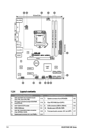
..., 3-pin CHA_FAN) 2. Front panel audio connector (10-1 pin AAFP) 1-17 1-21 1-4 ASUS P8H61-MX Series Intel® LGA1155 CPU socket 4. Standby power LED (SB_PWR) 1-1 1-20 11. 12... module) EATXPWR 24.4cm(9.6in) VGA LGA1155 USB3_12 LAN_USB12 ASM 1042 2 AUDIO P8H61-MX USB3 CHA_FAN PCIEX16 RTL 8111F Lithium Cell CMOS Power Super I/O PCIEX1_1 Intel® 64Mb...SATA3G_4 SATA3G_2 5 F_PANEL 11 10 9 8 76 1.2.4 Layout contents Connectors/Jumpers/Slots/LED 1. Clear RTC RAM (3-pin CLRTC) 1-15 1-4 9. Speaker connector (4-pin SPEAKER) Page 1-20 1-18 8. System panel...
..., 3-pin CHA_FAN) 2. Front panel audio connector (10-1 pin AAFP) 1-17 1-21 1-4 ASUS P8H61-MX Series Intel® LGA1155 CPU socket 4. Standby power LED (SB_PWR) 1-1 1-20 11. 12... module) EATXPWR 24.4cm(9.6in) VGA LGA1155 USB3_12 LAN_USB12 ASM 1042 2 AUDIO P8H61-MX USB3 CHA_FAN PCIEX16 RTL 8111F Lithium Cell CMOS Power Super I/O PCIEX1_1 Intel® 64Mb...SATA3G_4 SATA3G_2 5 F_PANEL 11 10 9 8 76 1.2.4 Layout contents Connectors/Jumpers/Slots/LED 1. Clear RTC RAM (3-pin CLRTC) 1-15 1-4 9. Speaker connector (4-pin SPEAKER) Page 1-20 1-18 8. System panel...
P8H61-MX R2.0 User's Manual
Page 29
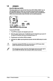
...the CMOS RTC RAM data. Chapter 1: Product introduction 1-19 After clearing the CMOS, reinstall the battery. The onboard button cell battery powers the RAM data in CMOS. You can clear the CMOS memory of date, time, and system setup parameters by erasing the CMOS RTC RAM data. P8H61-MX R2.0 CLRTC... 12 23 Normal (Default) Clear RTC P8H61-MX Series Clear RTC RAM To erase the RTC RAM: 1. Move the jumper cap...
...the CMOS RTC RAM data. Chapter 1: Product introduction 1-19 After clearing the CMOS, reinstall the battery. The onboard button cell battery powers the RAM data in CMOS. You can clear the CMOS memory of date, time, and system setup parameters by erasing the CMOS RTC RAM data. P8H61-MX R2.0 CLRTC... 12 23 Normal (Default) Clear RTC P8H61-MX Series Clear RTC RAM To erase the RTC RAM: 1. Move the jumper cap...
P8H61-MX R2.0 User's Manual
Page 41
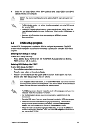
... 1.6 Jumpers for details. • If the system fails to boot after updating BIOS. • Load the BIOS default settings to erase the RTC RAM. DO NOT shut down the system properly from a running operating system can cause damage to exit BIOS Updater. If you have disconnected them. 2.2 BIOS...press . The BIOS screens include navigation keys and brief online help to turn the system off then back on your screen. • Visit the ASUS website at startup: • Press during the Power-On Self Test (POST). Entering BIOS Setup after POST To enter BIOS Setup after changing ...
... 1.6 Jumpers for details. • If the system fails to boot after updating BIOS. • Load the BIOS default settings to erase the RTC RAM. DO NOT shut down the system properly from a running operating system can cause damage to exit BIOS Updater. If you have disconnected them. 2.2 BIOS...press . The BIOS screens include navigation keys and brief online help to turn the system off then back on your screen. • Visit the ASUS website at startup: • Press during the Power-On Self Test (POST). Entering BIOS Setup after POST To enter BIOS Setup after changing ...

P8H61-MX R2.0 User's Manual
Page 45
... or User Password items on top of the screen show Installed. After you have forgotten your BIOS password, erase the CMOS Real Time Clock (RTC) RAM to clear the BIOS password. Chapter 2: BIOS information 2-9 Configuration options: [English] [Español 2.3.2 System Date [Day xx/xx/xxxx] Allows you to set the...
... or User Password items on top of the screen show Installed. After you have forgotten your BIOS password, erase the CMOS Real Time Clock (RTC) RAM to clear the BIOS password. Chapter 2: BIOS information 2-9 Configuration options: [English] [Español 2.3.2 System Date [Day xx/xx/xxxx] Allows you to set the...


