
P8H61-M PLUS V3 User's Manual
Page 6
... are connected. Contact a qualified service technician or your dealer immediately. • To avoid short circuits, keep paper clips, screws, and staples away from connectors, slots, sockets and circuitry. • Avoid dust, humidity, and temperature extremes. These devices could interrupt the grounding circuit. • Ensure that your power supply is broken, do...
... are connected. Contact a qualified service technician or your dealer immediately. • To avoid short circuits, keep paper clips, screws, and staples away from connectors, slots, sockets and circuitry. • Avoid dust, humidity, and temperature extremes. These devices could interrupt the grounding circuit. • Ensure that your power supply is broken, do...
P8H61-M PLUS V3 User's Manual
Page 9
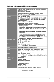
... at the back panel) ASUS ESD Guard ASUS GPU Boost ASUS Anti-Surge Protection ASUS UEFI BIOS ASUS CrashFree BIOS 3 ASUS EZ Flash 2 ASUS MyLogo 2™ 100% All High-quality Conductive Polymer Capacitors (continued on the next page) ix P8H61-M PLUS V3 specifications summary CPU Chipset Memory Expansion slots Storage LAN Audio USB ASUS unique features LGA1155 socket for Intel® 3rd...
... at the back panel) ASUS ESD Guard ASUS GPU Boost ASUS Anti-Surge Protection ASUS UEFI BIOS ASUS CrashFree BIOS 3 ASUS EZ Flash 2 ASUS MyLogo 2™ 100% All High-quality Conductive Polymer Capacitors (continued on the next page) ix P8H61-M PLUS V3 specifications summary CPU Chipset Memory Expansion slots Storage LAN Audio USB ASUS unique features LGA1155 socket for Intel® 3rd...
P8H61-M PLUS V3 User's Manual
Page 11
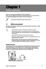
...the location of accessories. This is ON, in sleep mode, or in soft-off or the power cord is detached from the wall socket before touching any component. • Before handling components, use a grounded wrist strap or touch a safely grounded object or a metal...in any motherboard component. Failure to do so may cause severe damage to page x for buying an ASUS® P8H61-M PLUS V3 motherboard! SB_PWR P8H61-M PLUS V3 ON OFF Standby Power Powered Off P8H61-M PLUS V3 Onboard LED Chapter 1: Product introduction 1-1 Standby Power LED The motherboard comes with a standby power LED ...
...the location of accessories. This is ON, in sleep mode, or in soft-off or the power cord is detached from the wall socket before touching any component. • Before handling components, use a grounded wrist strap or touch a safely grounded object or a metal...in any motherboard component. Failure to do so may cause severe damage to page x for buying an ASUS® P8H61-M PLUS V3 motherboard! SB_PWR P8H61-M PLUS V3 ON OFF Standby Power Powered Off P8H61-M PLUS V3 Onboard LED Chapter 1: Product introduction 1-1 Standby Power LED The motherboard comes with a standby power LED ...

P8H61-M PLUS V3 User's Manual
Page 13
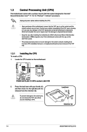
... 1: Product introduction 1-3 Clear RTC RAM (3-pin CLRTC) Page 1-15 1-18 9. ATX power connectors (24-pin EATXPWR, 4-pin ATX12V) 3. Intel® LGA1155 CPU socket 4. USB connectors (10-1 pin USB78, USB910) 1-20 1-4 10. System panel connector (20-8 pin PANEL) 7. DDR3 DIMM slots 5. 1.2.3 Motherboard layout 1 2 ...module) EATXPWR 24.4cm(9.6in) LPT VGA LGA1155 USB34 2 LAN1_USB12 AUDIO RTL 8111E Lithium Cell CMOS Power CHA_FAN PCIEX16 P8H61-M PLUS V3 Super I/O PCIEX1_1 ASM 1083 PCI1 64Mb BIOS Intel® H61 SB_PWR ALC 887-VD SPDIF_OUT PCI2 SATA3G_3 SATA3G_1 5 USB56...
... 1: Product introduction 1-3 Clear RTC RAM (3-pin CLRTC) Page 1-15 1-18 9. ATX power connectors (24-pin EATXPWR, 4-pin ATX12V) 3. Intel® LGA1155 CPU socket 4. USB connectors (10-1 pin USB78, USB910) 1-20 1-4 10. System panel connector (20-8 pin PANEL) 7. DDR3 DIMM slots 5. 1.2.3 Motherboard layout 1 2 ...module) EATXPWR 24.4cm(9.6in) LPT VGA LGA1155 USB34 2 LAN1_USB12 AUDIO RTL 8111E Lithium Cell CMOS Power CHA_FAN PCIEX16 P8H61-M PLUS V3 Super I/O PCIEX1_1 ASM 1083 PCI1 64Mb BIOS Intel® H61 SB_PWR ALC 887-VD SPDIF_OUT PCI2 SATA3G_3 SATA3G_1 5 USB56...
P8H61-M PLUS V3 User's Manual
Page 14
... you see any damage to the socket pins, do not remove the PnP cap unless you are not bent. Contact your thumb (A), and then move it is on the motherboard. Load lever A B Retention tab 1-4 ASUS P8H61-M PLUS V3 ASUS will process Return Merchandise Authorization (RMA...) requests only if the motherboard comes with a surface mount LGA1155 socket designed for the Intel® Second Generation Core™ i7 / i5 / i3 / Pentium...
... you see any damage to the socket pins, do not remove the PnP cap unless you are not bent. Contact your thumb (A), and then move it is on the motherboard. Load lever A B Retention tab 1-4 ASUS P8H61-M PLUS V3 ASUS will process Return Merchandise Authorization (RMA...) requests only if the motherboard comes with a surface mount LGA1155 socket designed for the Intel® Second Generation Core™ i7 / i5 / i3 / Pentium...

P8H61-M PLUS V3 User's Manual
Page 15
... direction of the arrow until the load plate is on the bottom‑left corner of the socket, and then fit the socket alignment keys into the socket to prevent bending the connectors on the socket and damaging the CPU! PnP cap 5. DO NOT force the CPU into the CPU notches.... 3. Gold triangle mark Alignment keys CPU notches Chapter 1: Product introduction 1-5 Position the CPU over the socket, ensuring that...
... direction of the arrow until the load plate is on the bottom‑left corner of the socket, and then fit the socket alignment keys into the socket to prevent bending the connectors on the socket and damaging the CPU! PnP cap 5. DO NOT force the CPU into the CPU notches.... 3. Gold triangle mark Alignment keys CPU notches Chapter 1: Product introduction 1-5 Position the CPU over the socket, ensuring that...

P8H61-M PLUS V3 User's Manual
Page 17
The illustration above is incompatible with the LGA775 and LGA1366 sockets in place. A B 1 1 B A The type of the installed CPU, ensuring that you use only Intel®‑certified multi‑directional heatsink and fan. • Your... no tool to the CPU fan connector. 2. If you buy a boxed Intel® processor, the package includes the CPU fan and heatsink assembly. The LGA1155 socket is for reference only. Chapter 1: Product introduction 1-7 To install the CPU heatsink and fan: A 1. B B Orient the heatsink and fan assembly A such that you have ...
The illustration above is incompatible with the LGA775 and LGA1366 sockets in place. A B 1 1 B A The type of the installed CPU, ensuring that you use only Intel®‑certified multi‑directional heatsink and fan. • Your... no tool to the CPU fan connector. 2. If you buy a boxed Intel® processor, the package includes the CPU fan and heatsink assembly. The LGA1155 socket is for reference only. Chapter 1: Product introduction 1-7 To install the CPU heatsink and fan: A 1. B B Orient the heatsink and fan assembly A such that you have ...

P8H61-M PLUS V3 User's Manual
Page 19
...modules are developed for better performance with two Double Data Rate 3 (DDR3) Dual Inline Memory Modules (DIMM) sockets. Rotate each fastener clockwise to prevent installation on a DDR2 DIMM socket. A DDR3 module has the same physical dimensions as a DDR2 DIMM but is notched differently to ensure correct ...heatsink and fan assembly from the motherboard. 5. The figure illustrates the location of the DDR3 DIMM sockets: DIMM_A1 DIMM_B1 P8H61-M PLUS V3 Channel Channel A Channel B Sockets DIMM_A1 DIMM_B1 P8H61-M PLUS V3 240-pin DDR3 DIMM sockets Chapter 1: Product introduction 1-9
...modules are developed for better performance with two Double Data Rate 3 (DDR3) Dual Inline Memory Modules (DIMM) sockets. Rotate each fastener clockwise to prevent installation on a DDR2 DIMM socket. A DDR3 module has the same physical dimensions as a DDR2 DIMM but is notched differently to ensure correct ...heatsink and fan assembly from the motherboard. 5. The figure illustrates the location of the DDR3 DIMM sockets: DIMM_A1 DIMM_B1 P8H61-M PLUS V3 Channel Channel A Channel B Sockets DIMM_A1 DIMM_B1 P8H61-M PLUS V3 240-pin DDR3 DIMM sockets Chapter 1: Product introduction 1-9

P8H61-M PLUS V3 User's Manual
Page 20
... Vendors Lists (QVL) DDR3-2666 (O.C.) MHz capability Vendors Part No. Timing - DIMM socket support Voltage (optional) 1 DIMM 2 DIMMs 1.65V • • 1-10 ASUS P8H61-M PLUS V3 For optimum compatibility, we recommend that you install 4GB or more memory on 32-bit Windows® OS... lower frequency than the vendor-marked value. Size SS/DS KINGSTON KHX2250C9D3T1K2/4GX(XMP) 4GB(2 x 2GB) DS Chip Brand Chip NO. - - DIMM socket support Timing Voltage (optional) 1 DIMM 2 DIMMs - 1.65V • • DDR3 1600 MHz and higher memory frequency is recommended to protect the ...
... Vendors Lists (QVL) DDR3-2666 (O.C.) MHz capability Vendors Part No. Timing - DIMM socket support Voltage (optional) 1 DIMM 2 DIMMs 1.65V • • 1-10 ASUS P8H61-M PLUS V3 For optimum compatibility, we recommend that you install 4GB or more memory on 32-bit Windows® OS... lower frequency than the vendor-marked value. Size SS/DS KINGSTON KHX2250C9D3T1K2/4GX(XMP) 4GB(2 x 2GB) DS Chip Brand Chip NO. - - DIMM socket support Timing Voltage (optional) 1 DIMM 2 DIMMs - 1.65V • • DDR3 1600 MHz and higher memory frequency is recommended to protect the ...

P8H61-M PLUS V3 User's Manual
Page 22
Visit the ASUS website at www.asus.com for the latest QVL. 1-12 ASUS P8H61-M PLUS V3 Size SS/ DS Chip Brand Chip NO. Crucial CT12864BA1067.8FF ELPIDA EBJ21UE8EDF0-AE-F KINGSTON KVR1066D3N7/4G Size SS/DS Chip Brand 1GB ...SS 2GB DS 4GB DS Micron ELPIDA Hynix Chip NO. 9GF22D9KPT J1108EDSE-DJ-F H5TQ2G83AFR Timing Voltage 7 - - 1.35V(low voltage) 7 1.5V DIMM socket support (optional) 1...
Visit the ASUS website at www.asus.com for the latest QVL. 1-12 ASUS P8H61-M PLUS V3 Size SS/ DS Chip Brand Chip NO. Crucial CT12864BA1067.8FF ELPIDA EBJ21UE8EDF0-AE-F KINGSTON KVR1066D3N7/4G Size SS/DS Chip Brand 1GB ...SS 2GB DS 4GB DS Micron ELPIDA Hynix Chip NO. 9GF22D9KPT J1108EDSE-DJ-F H5TQ2G83AFR Timing Voltage 7 - - 1.35V(low voltage) 7 1.5V DIMM socket support (optional) 1...

P8H61-M PLUS V3 User's Manual
Page 23
... that the notch on the DIMM matches the DIMM slot key on the socket. 2 DIMM notch 1 1 Unlocked retaining clip DIMM slot key A DIMM is properly seated. The DIMM... DIMM lightly with extra force. 1 2. Failure to do so can cause severe damage to unlock a DIMM socket. 2. DO NOT force a DIMM into the socket until the retaining clips snap back in place 3 and the DIMM is keyed with a notch so that it... Product introduction 1-13 Locked Retaining Clip 1.4.4 Removing a DIMM To remove a DIMM: 1. Firmly insert the DIMM into a socket in only one direction. Remove the DIMM from the...
... that the notch on the DIMM matches the DIMM slot key on the socket. 2 DIMM notch 1 1 Unlocked retaining clip DIMM slot key A DIMM is properly seated. The DIMM... DIMM lightly with extra force. 1 2. Failure to do so can cause severe damage to unlock a DIMM socket. 2. DO NOT force a DIMM into the socket until the retaining clips snap back in place 3 and the DIMM is keyed with a notch so that it... Product introduction 1-13 Locked Retaining Clip 1.4.4 Removing a DIMM To remove a DIMM: 1. Firmly insert the DIMM into a socket in only one direction. Remove the DIMM from the...


