
User Manual
Page 8
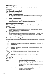
... Enter or Return key. About this guide This user guide contains the information you MUST follow to complete a task. ASUS websites The ASUS website provides updated information on ASUS hardware and software products. Optional documentation Your product package may include optional documentation, such as warranty flyers, that you complete... a plus sign (+). NOTE: Tips and additional information to help you must press two or more information Refer to change system settings through the BIOS Setup menus. Example: means that may have been added by your dealer. Where to the...
... Enter or Return key. About this guide This user guide contains the information you MUST follow to complete a task. ASUS websites The ASUS website provides updated information on ASUS hardware and software products. Optional documentation Your product package may include optional documentation, such as warranty flyers, that you complete... a plus sign (+). NOTE: Tips and additional information to help you must press two or more information Refer to change system settings through the BIOS Setup menus. Example: means that may have been added by your dealer. Where to the...
User Manual
Page 28
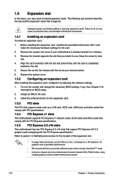
...earlier. 6. Remove the bracket opposite the slot that support PCI Express x16 2.0 graphic cards complying with it and make the necessary hardware settings for the expansion card. 1.5.3 PCI slots The PCI slots support cards such as a LAN card, SCSI card, USB card, and...the card. 3. Before installing the expansion card, read the documentation that it by adjusting the software settings. 1. Keep the screw for information on the system and change the necessary BIOS settings, if any. 1.5 Expansion slot In the future, you physical injury and damage motherboard components. 1.5.1...
...earlier. 6. Remove the bracket opposite the slot that support PCI Express x16 2.0 graphic cards complying with it and make the necessary hardware settings for the expansion card. 1.5.3 PCI slots The PCI slots support cards such as a LAN card, SCSI card, USB card, and...the card. 3. Before installing the expansion card, read the documentation that it by adjusting the software settings. 1. Keep the screw for information on the system and change the necessary BIOS settings, if any. 1.5 Expansion slot In the future, you physical injury and damage motherboard components. 1.5.1...
User Manual
Page 29
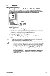
You can automatically reset parameter settings to default values. • Due to the chipset behavior, AC power off and... the cap on pins 2-3 for about 5-10 seconds, then move the jumper again to clear the CMOS RTC RAM data. ASUS P7P55D LE 1-17 To erase the RTC RAM: 1. After the CMOS clearance, reinstall the battery. • You do not help, ...in CMOS, which include system setup information such as system passwords. Shut down the key during the boot process and enter BIOS setup to pins 1-2. 3. Removing the cap will cause system boot failure! • If the steps above do not...
You can automatically reset parameter settings to default values. • Due to the chipset behavior, AC power off and... the cap on pins 2-3 for about 5-10 seconds, then move the jumper again to clear the CMOS RTC RAM data. ASUS P7P55D LE 1-17 To erase the RTC RAM: 1. After the CMOS clearance, reinstall the battery. • You do not help, ...in CMOS, which include system setup information such as system passwords. Shut down the key during the boot process and enter BIOS setup to pins 1-2. 3. Removing the cap will cause system boot failure! • If the steps above do not...
User Manual
Page 30
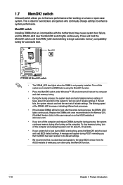
... lights continuously. function. 1-18 Chapter 1: Product introduction switch Installing DIMMs that you download and update to the latest BIOS version from the ASUS website at www.asus.com. • If you turn off the computer and replace DIMMs during POST reminding you to begin automatic memory ...To stop memory tuning, turn off the computer and unplog the power cord for the system to boot and load BIOS default settings. switch to test one set of failsafe settings. Press and hold the MemOK! function. • Press the MemOK! It takes about 30 seconds for about ...
... lights continuously. function. 1-18 Chapter 1: Product introduction switch Installing DIMMs that you download and update to the latest BIOS version from the ASUS website at www.asus.com. • If you turn off the computer and replace DIMMs during POST reminding you to begin automatic memory ...To stop memory tuning, turn off the computer and unplog the power cord for the system to boot and load BIOS default settings. switch to test one set of failsafe settings. Press and hold the MemOK! function. • Press the MemOK! It takes about 30 seconds for about ...
User Manual
Page 33
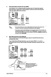
...module to this connector to [HD Audio]. ASUS P7P55D LE 1-21 Serial ATA connectors (7-pin SATA1-6) These connectors are for the Serial ATA signal cables for a chassis-mounted front panel audio I /O module cable to this connector, set the Front Panel Type item in the BIOS setup to avail of the motherboard's high..., this connector is for Serial ATA hard disk drives and optical disc drives. Front panel audio connector (10-1 pin AAFP) This connector is set the item to [HD Audio]. 4. If you installed Serial ATA hard disk drives, you want to connect an AC'97 front panel audio ...
...module to this connector to [HD Audio]. ASUS P7P55D LE 1-21 Serial ATA connectors (7-pin SATA1-6) These connectors are for the Serial ATA signal cables for a chassis-mounted front panel audio I /O module cable to this connector, set the Front Panel Type item in the BIOS setup to avail of the motherboard's high..., this connector is for Serial ATA hard disk drives and optical disc drives. Front panel audio connector (10-1 pin AAFP) This connector is set the item to [HD Audio]. 4. If you installed Serial ATA hard disk drives, you want to connect an AC'97 front panel audio ...
User Manual
Page 34
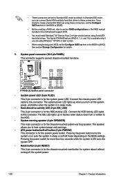
...The IDE LED lights up when you turn on the BIOS settings. If you are set to Standard IDE mode by default. The Serial ATA RAID feature (RAID 0, 1, 5, and 10) is available only if you intend to create a Serial ATA RAID set using Serial ATA hard disk drives. The system power ...4-pin connector is for details. 5. The speaker allows you can connect Serial ATA boot/data hard disk drives to these connectors, set the Configure SATA as item in the BIOS to [AHCI]. System panel connector (20-8 pin PANEL) This connector supports several chassis-mounted functions. • System power LED ...
...The IDE LED lights up when you turn on the BIOS settings. If you are set to Standard IDE mode by default. The Serial ATA RAID feature (RAID 0, 1, 5, and 10) is available only if you intend to create a Serial ATA RAID set using Serial ATA hard disk drives. The system power ...4-pin connector is for details. 5. The speaker allows you can connect Serial ATA boot/data hard disk drives to these connectors, set the Configure SATA as item in the BIOS to [AHCI]. System panel connector (20-8 pin PANEL) This connector supports several chassis-mounted functions. • System power LED ...

User Manual
Page 40
...P7P55D LE VER: 0212 (H:00 B:06) DATE: 06/11/2009 Update ROM BOARD: Unknown VER: Unknown DATE: Unknown PATH: A:\ A: Note [Enter] Select or Load [Tab] Switch [Up/Down/Home/End] Move [B] Backup [V] Drive Info [ESC] Exit 2-2 Chapter 2: BIOS information Locate the BIOS file from a file, then click Next. Ensure to load the BIOS default settings.... 2.1.2 ASUS EZ Flash 2 The ASUS EZ Flash 2 feature allows you start using EZ Flash 2: 1. To update the BIOS using this utility, download the latest BIOS file from a BIOS file a. Insert the USB flash disk that contains the latest BIOS file to...
...P7P55D LE VER: 0212 (H:00 B:06) DATE: 06/11/2009 Update ROM BOARD: Unknown VER: Unknown DATE: Unknown PATH: A:\ A: Note [Enter] Select or Load [Tab] Switch [Up/Down/Home/End] Move [B] Backup [V] Drive Info [ESC] Exit 2-2 Chapter 2: BIOS information Locate the BIOS file from a file, then click Next. Ensure to load the BIOS default settings.... 2.1.2 ASUS EZ Flash 2 The ASUS EZ Flash 2 feature allows you start using EZ Flash 2: 1. To update the BIOS using this utility, download the latest BIOS file from a BIOS file a. Insert the USB flash disk that contains the latest BIOS file to...
User Manual
Page 41
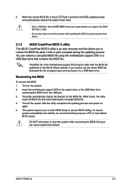
...BIOS setting. Turn off the system after the utility completes the updating process and power on the system. 2. DO NOT shut down or reset the system while updating the BIOS to prevent system boot failure! 2.1.3 ASUS CrashFree BIOS 3 utility The ASUS CrashFree BIOS 3 utility is found , the utility reads the BIOS...drive containing the BIOS file to a USB flash drive. The system requires you to restore the BIOS file when it to the USB port. 3. ASUS P7P55D LE 2-3 The BIOS file in the motherboard support DVD may be older than the BIOS file published on the ASUS official website....
...BIOS setting. Turn off the system after the utility completes the updating process and power on the system. 2. DO NOT shut down or reset the system while updating the BIOS to prevent system boot failure! 2.1.3 ASUS CrashFree BIOS 3 utility The ASUS CrashFree BIOS 3 utility is found , the utility reads the BIOS...drive containing the BIOS file to a USB flash drive. The system requires you to restore the BIOS file when it to the USB port. 3. ASUS P7P55D LE 2-3 The BIOS file in the motherboard support DVD may be older than the BIOS file published on the ASUS official website....
User Manual
Page 42
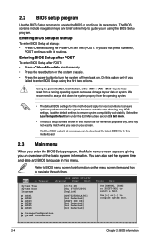
... [SHIFT-TAB] to configure system Date. 2-4 Chapter 2: BIOS information If you do not press , POST continues with its parameters. Entering BIOS Setup at startup To enter BIOS Setup at www.asus.com to download the latest BIOS file for this menu. If the system becomes unstable after ...to navigate through them. 2.2 BIOS setup program Use the BIOS Setup program to update the BIOS or configure its routines. Entering BIOS Setup after POST To enter BIOS Setup after changing any BIOS settings, load the default settings to enter BIOS Setup using the BIOS Setup program. Select the ...
... [SHIFT-TAB] to configure system Date. 2-4 Chapter 2: BIOS information If you do not press , POST continues with its parameters. Entering BIOS Setup at startup To enter BIOS Setup at www.asus.com to download the latest BIOS file for this menu. If the system becomes unstable after ...to navigate through them. 2.2 BIOS setup program Use the BIOS Setup program to update the BIOS or configure its routines. Entering BIOS Setup after POST To enter BIOS Setup after changing any BIOS settings, load the default settings to enter BIOS Setup using the BIOS Setup program. Select the ...
User Manual
Page 43
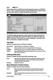
...Inc. Allows automatic selection of IDE/SATA devices. Disables this option if no IDE device is installed. When set to [Auto], the data transfer from and to the device occurs in the system. Select this mode, and.... [Not Installed] [Auto] [CDROM] [ARMD] Select this function. These values are specifically configuring a CD-ROM drive. The BIOS automatically detects the values opposite the dimmed items (Device, Vendor, Size, LBA Mode, Block Mode, PIO Mode, Async DMA, Ultra...] to select the type of device connected to display the SATA device information. ASUS P7P55D LE 2-5
...Inc. Allows automatic selection of IDE/SATA devices. Disables this option if no IDE device is installed. When set to [Auto], the data transfer from and to the device occurs in the system. Select this mode, and.... [Not Installed] [Auto] [CDROM] [ARMD] Select this function. These values are specifically configuring a CD-ROM drive. The BIOS automatically detects the values opposite the dimmed items (Device, Vendor, Size, LBA Mode, Block Mode, PIO Mode, Async DMA, Ultra...] to select the type of device connected to display the SATA device information. ASUS P7P55D LE 2-5
User Manual
Page 44
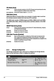
... as [Enhanced] [IDE] Hard Disk Write Protect [Disabled] IDE Detect Time Out (Sec) [35] Set [Compatible Mode] when Legacy OS (i.e. Main BIOS SETUP UTILITY Storage Configuration SATA Configuraton Configure SATA as fewer transactions are needed for the transfer of a particular...Analysis, and Reporting Technology). [Enabled] Enables the S.M.A.R.T feature. [Disabled] Disables the S.M.A.R.T feature. 32Bit Data Transfer [Enabled] [Enabled] Sets the IDE controller to combine two 16-bit reads from the hardware devices installed with much less CPU overhead. The DMA mode consists of...
... as [Enhanced] [IDE] Hard Disk Write Protect [Disabled] IDE Detect Time Out (Sec) [35] Set [Compatible Mode] when Legacy OS (i.e. Main BIOS SETUP UTILITY Storage Configuration SATA Configuraton Configure SATA as fewer transactions are needed for the transfer of a particular...Analysis, and Reporting Technology). [Enabled] Enables the S.M.A.R.T feature. [Disabled] Disables the S.M.A.R.T feature. 32Bit Data Transfer [Enabled] [Enabled] Sets the IDE controller to combine two 16-bit reads from the hardware devices installed with much less CPU overhead. The DMA mode consists of...
User Manual
Page 45
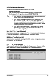
... storage driver to enable advanced Serial ATA features that increases storage performance on random workloads by the Southbridge chip. Main AHCI Settings BIOS SETUP UTILITY SATA Port1 [Not Detected] SATA Port2 [Not Detected] SATA Port3 [Not Detected] SATA Port4 [Not Detected] ...ASUS P7P55D LE 2-7 Configuration options: [0] [5] [10] [15] [20] [25] [30] [35] 2.3.3 AHCI Configuration This menu is accessed through BIOS. This will be effective only if the device is the section for detecting ATA/ATAPI devices. It appears only when you set the item Configure SATA as [IDE] Sets...
... storage driver to enable advanced Serial ATA features that increases storage performance on random workloads by the Southbridge chip. Main AHCI Settings BIOS SETUP UTILITY SATA Port1 [Not Detected] SATA Port2 [Not Detected] SATA Port3 [Not Detected] SATA Port4 [Not Detected] ...ASUS P7P55D LE 2-7 Configuration options: [0] [5] [10] [15] [20] [25] [30] [35] 2.3.3 AHCI Configuration This menu is accessed through BIOS. This will be effective only if the device is the section for detecting ATA/ATAPI devices. It appears only when you set the item Configure SATA as [IDE] Sets...
User Manual
Page 46
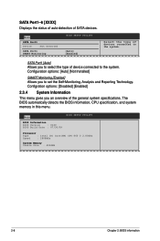
... of the general system specifications. SATA Port1 [Auto] Allows you to set the Self-Monitoring, Analysis and Reporting Technology. The BIOS automatically detects the BIOS information, CPU specification, and system memory in this menu. Main BIOS Information BIOS Version : 0120 BIOS Build Date : 07/30/09 BIOS SETUP UTILITY Processor Type : Intel (R) Core(TM) CPU 860 @ 2.80GHz...
... of the general system specifications. SATA Port1 [Auto] Allows you to set the Self-Monitoring, Analysis and Reporting Technology. The BIOS automatically detects the BIOS information, CPU specification, and system memory in this menu. Main BIOS Information BIOS Version : 0120 BIOS Build Date : 07/30/09 BIOS SETUP UTILITY Processor Type : Intel (R) Core(TM) CPU 860 @ 2.80GHz...
User Manual
Page 47
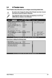
... the Ai Tweaker menu items. Incorrect field values can cause the system to Tuner BCLK. ASUS P7P55D LE 2-9 Main Ai Tweaker BIOS SETUP UTILITY Advanced Power Boot Configure System Performance Settings Ai Overclock Tuner CPU Ratio Setting Intel(R) SpeedStep(TM) Tech Intel(R) TurboMode Tech Xtreme Phase Full Power Mode DRAM Frequency QPI Frenquency [Auto] [Auto] [Enabled...
... the Ai Tweaker menu items. Incorrect field values can cause the system to Tuner BCLK. ASUS P7P55D LE 2-9 Main Ai Tweaker BIOS SETUP UTILITY Advanced Power Boot Configure System Performance Settings Ai Overclock Tuner CPU Ratio Setting Intel(R) SpeedStep(TM) Tech Intel(R) TurboMode Tech Xtreme Phase Full Power Mode DRAM Frequency QPI Frenquency [Auto] [Auto] [Enabled...
User Manual
Page 48
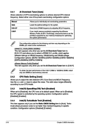
... [DDR3-1866MHz] [DDR3-2000MHz] [DDR3-2133MHz] eXtreme Memory Profile [Disabled] This item appears only when you set to [Auto]. When set the Ratio CMOS Setting item to [Enabled], the CPU speed is controlled by the operating system. Configuration options: [Disabled] [Enabled] ... CPU overclocking options to run faster than marked frequency in specific condition. Configuration options: [Disabled] [Enabled] 2-10 Chapter 2: BIOS information The configuration options for the system. If you to [X.M.P.] To obtain the best performance of the preset overclocking configuration options:...
... [DDR3-1866MHz] [DDR3-2000MHz] [DDR3-2133MHz] eXtreme Memory Profile [Disabled] This item appears only when you set to [Auto]. When set the Ratio CMOS Setting item to [Enabled], the CPU speed is controlled by the operating system. Configuration options: [Disabled] [Enabled] ... CPU overclocking options to run faster than marked frequency in specific condition. Configuration options: [Disabled] [Enabled] 2-10 Chapter 2: BIOS information The configuration options for the system. If you to [X.M.P.] To obtain the best performance of the preset overclocking configuration options:...
User Manual
Page 50
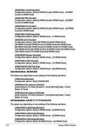
... options: [Auto] [1 DRAM Clock] - [63 DRAM Clock] 2nd Information: 3N-255-255 The values vary depending on your settings of the following sub-items: DRAM Timing Mode [Auto] Configuration options: [Auto] [1N] [2N] [3N] DRAM Round Trip...Clock] [Normal] [Delay 1 Clock] [Delay 15 Clock] 3rd Information: 8-8-25-17-17-17-9-9-6-9-9-6 The values vary depending on your settings of the following sub-items: DRAM WRITE to READ Delay(DD) [Auto] Configuration options: [Auto] [1 DRAM Clock] - [8 DRAM...(SR) [Auto] Configuration options: [Auto] [10 DRAM Clock] - [22 DRAM Clock] 2-12 Chapter 2: BIOS information
... options: [Auto] [1 DRAM Clock] - [63 DRAM Clock] 2nd Information: 3N-255-255 The values vary depending on your settings of the following sub-items: DRAM Timing Mode [Auto] Configuration options: [Auto] [1N] [2N] [3N] DRAM Round Trip...Clock] [Normal] [Delay 1 Clock] [Delay 15 Clock] 3rd Information: 8-8-25-17-17-17-9-9-6-9-9-6 The values vary depending on your settings of the following sub-items: DRAM WRITE to READ Delay(DD) [Auto] Configuration options: [Auto] [1 DRAM Clock] - [8 DRAM...(SR) [Auto] Configuration options: [Auto] [10 DRAM Clock] - [22 DRAM Clock] 2-12 Chapter 2: BIOS information
User Manual
Page 52
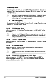
... range from 1.8V to 2.1V with the voltage requirement below 1.65V. 2.4.14 CPU PLL Voltage [Auto] Allows you to set the DRAM voltage. Different ratio might enhance DRAM overclocking ability. 2-14 Chapter 2: BIOS information The values range from 1.1V to 1.45V* with voltage requirement over 1.65V may make the system unstable. 2.4.12...
... range from 1.8V to 2.1V with the voltage requirement below 1.65V. 2.4.14 CPU PLL Voltage [Auto] Allows you to set the DRAM voltage. Different ratio might enhance DRAM overclocking ability. 2-14 Chapter 2: BIOS information The values range from 1.1V to 1.45V* with voltage requirement over 1.65V may make the system unstable. 2.4.12...
User Manual
Page 54
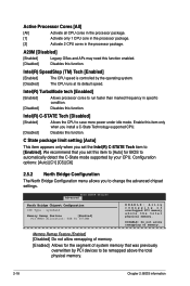
...C-STATE Tech [Disabled] v02.61 (C)Copyright 1985-2009, American Megatrends, Inc. 2-16 Chapter 2: BIOS information NOTE: Please key in this screen may differ. BIOS SETUP UTILITY Advanced Configure advanced CPU settings Module Version:01.04 Manufacturer:Intel Brand String:Intel(R) Core(TM) CPU 860@ 2.80GHz Frequency :2.... ratio between CPU Core Clock and the BCLK Frequency. NOTE: If an invalid ratio is set in this menu show the CPU-related information that the BIOS automatically detects. The items shown in CMOS then actual and setpoint values may be different due to the...
...C-STATE Tech [Disabled] v02.61 (C)Copyright 1985-2009, American Megatrends, Inc. 2-16 Chapter 2: BIOS information NOTE: Please key in this screen may differ. BIOS SETUP UTILITY Advanced Configure advanced CPU settings Module Version:01.04 Manufacturer:Intel Brand String:Intel(R) Core(TM) CPU 860@ 2.80GHz Frequency :2.... ratio between CPU Core Clock and the BCLK Frequency. NOTE: If an invalid ratio is set in this menu show the CPU-related information that the BIOS automatically detects. The items shown in CMOS then actual and setpoint values may be different due to the...
User Manual
Page 56
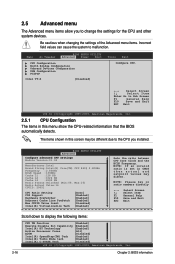
...: [Auto] [C1] [C3] [C6] 2.5.2 North Bridge Configuration The North Bridge Configuration menu allows you set this item to [Auto] for the segment of memory. [Enabled] Allows for BIOS to run faster than marked frequency in the processor package. Intel(R) SpeedStep (TM) Tech [Enabled] [Enabled]...power under idle mode. Enable this item only when you set the Intel(R) C-STATE Tech item to change the advanced chipset settings. C State package limit setting [Auto] This item appears only when you to [Enabled]. BIOS SETUP UTILITY Advanced North Bridge Chipset Configuration IMC Type : ...
...: [Auto] [C1] [C3] [C6] 2.5.2 North Bridge Configuration The North Bridge Configuration menu allows you set this item to [Auto] for the segment of memory. [Enabled] Allows for BIOS to run faster than marked frequency in the processor package. Intel(R) SpeedStep (TM) Tech [Enabled] [Enabled]...power under idle mode. Enable this item only when you set the Intel(R) C-STATE Tech item to change the advanced chipset settings. C State package limit setting [Auto] This item appears only when you to [Enabled]. BIOS SETUP UTILITY Advanced North Bridge Chipset Configuration IMC Type : ...
User Manual
Page 66
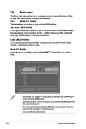
..., and choose a profile to display the submenu. 2.8.1 ASUS O.C. Profile Allows you to save your profile name and press , and then choose a profile number to save the current BIOS file to the BIOS Flash. Profile Utility V2.00b Current CMOS BOARD: P7P55D LE VER: 0166 DATE: 07/08/2009 Restore CMOS BOARD:Unknown... single partition only. • DO NOT shut down or reset the system while updating the BIOS to prevent the system boot failure! • We recommend that you to load the previous BIOS settings saved in the Save to sub-item. ASUSTek O.C. Profile This item allows you to configure ...
..., and choose a profile to display the submenu. 2.8.1 ASUS O.C. Profile Allows you to save your profile name and press , and then choose a profile number to save the current BIOS file to the BIOS Flash. Profile Utility V2.00b Current CMOS BOARD: P7P55D LE VER: 0166 DATE: 07/08/2009 Restore CMOS BOARD:Unknown... single partition only. • DO NOT shut down or reset the system while updating the BIOS to prevent the system boot failure! • We recommend that you to load the previous BIOS settings saved in the Save to sub-item. ASUSTek O.C. Profile This item allows you to configure ...


