
User Manual
Page 4
... 2.10.1 Using the OS shut down function 2-50 2.10.2 Using the dual function power switch 2-50 Chapter 3: BIOS setup 3.1 Managing and updating your BIOS 3-1 3.1.1 ASUS Update utility 3-1 3.1.2 ASUS EZ Flash 2 utility 3-4 3.1.3 BUPDATER utility 3-5 3.1.4 ASUS CrashFree BIOS 3 utility 3-6 3.2 BIOS setup program 3-7 3.2.1 BIOS menu screen 3-8 3.3.2 Menu bar 3-8 3.2.3 Navigation keys 3-8 3.2.4 Menu items 3-9 3.2.5 Submenu items 3-9 3.2.6 Configuration fields 3-9 3.2.7 Pop-up window 3-9 3.2.8 Scroll bar...
... 2.10.1 Using the OS shut down function 2-50 2.10.2 Using the dual function power switch 2-50 Chapter 3: BIOS setup 3.1 Managing and updating your BIOS 3-1 3.1.1 ASUS Update utility 3-1 3.1.2 ASUS EZ Flash 2 utility 3-4 3.1.3 BUPDATER utility 3-5 3.1.4 ASUS CrashFree BIOS 3 utility 3-6 3.2 BIOS setup program 3-7 3.2.1 BIOS menu screen 3-8 3.3.2 Menu bar 3-8 3.2.3 Navigation keys 3-8 3.2.4 Menu items 3-9 3.2.5 Submenu items 3-9 3.2.6 Configuration fields 3-9 3.2.7 Pop-up window 3-9 3.2.8 Scroll bar...
User Manual
Page 7
... CUDA-ready graphics cards 5-11 vii Creating a RAID driver disk 4-32 4.7.1 Creating a RAID driver disk without entering the OS.... 4-32 4.7.2 Creating a RAID driver disk in BIOS 4-28 4.6.4 Intel® Matrix Storage Manager option ROM utility......... 4-28 4.
... CUDA-ready graphics cards 5-11 vii Creating a RAID driver disk 4-32 4.7.1 Creating a RAID driver disk without entering the OS.... 4-32 4.7.2 Creating a RAID driver disk in BIOS 4-28 4.6.4 Intel® Matrix Storage Manager option ROM utility......... 4-28 4.

User Manual
Page 10
...when installing and configuring the motherboard. Detailed descriptions of the BIOS parameters are not part of the switches, jumpers, and connectors on ASUS hardware and software products. Refer to change system settings through the BIOS Setup menus. Where to find more information Refer to the...® CrossFireX™ and NVIDIA® SLI™ graphics cards. ASUS websites The ASUS website provides updated information on the motherboard. • Chapter 3: BIOS setup This chapter tells how to the ASUS contact information. 2. How this guide This user guide contains the information ...
...when installing and configuring the motherboard. Detailed descriptions of the BIOS parameters are not part of the switches, jumpers, and connectors on ASUS hardware and software products. Refer to change system settings through the BIOS Setup menus. Where to find more information Refer to the...® CrossFireX™ and NVIDIA® SLI™ graphics cards. ASUS websites The ASUS website provides updated information on the motherboard. • Chapter 3: BIOS setup This chapter tells how to the ASUS contact information. 2. How this guide This user guide contains the information ...

User Manual
Page 12
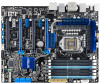
...x 1200 @ 60Hz Supports RGB with max. P7F7-E WS Supercomputer specifications summary CPU Chipset Memory On-board VGA ...definition, DIMMs of DDR3-1333 or above are supported by specific CPU models only. * Please load X.M.P in BIOS for Clarkdale processor) Intel® 3450 Chipset - �6��x�S��A�T�A�1��... 2.0 ports (6 ports at mid-board, 6 ports at back panel) (continued on the CPU types. ** Refer to www.asus.com for Intel CPU support list Intel® 3450 Chipset Nvidia NF200*1 6 x DIMM, max. 16GB, DDR3 2000(O.C.)* /1333...
...x 1200 @ 60Hz Supports RGB with max. P7F7-E WS Supercomputer specifications summary CPU Chipset Memory On-board VGA ...definition, DIMMs of DDR3-1333 or above are supported by specific CPU models only. * Please load X.M.P in BIOS for Clarkdale processor) Intel® 3450 Chipset - �6��x�S��A�T�A�1��... 2.0 ports (6 ports at mid-board, 6 ports at back panel) (continued on the CPU types. ** Refer to www.asus.com for Intel CPU support list Intel® 3450 Chipset Nvidia NF200*1 6 x DIMM, max. 16GB, DDR3 2000(O.C.)* /1333...

User Manual
Page 13
... ASUS Fanless Design: Stack Cool 3+ - ASUS Q-DIMM - Multi-language BIOS 4 x PCIe x16 slots G.P. MemOK! - ASUS CrashFree BIOS 3 - LED ASUS WS Heartbeat 64 Mb flash ROM, AMI BIOS, Green, PnP, DMI v2.0, ACPI v2.0a, SMBIOS v 2.6; ASUS O.C. ASUS MyLogo 2 - ASUS Q-Connector - WOL/WOR by PME (continued on board ASUS SASsaby series Cards support ASUS WS Diag. P7F7-E WS Supercomputer specifications summary 1394 Audio ASUS Special Features Workstation Unique Features BIOS...
... ASUS Fanless Design: Stack Cool 3+ - ASUS Q-DIMM - Multi-language BIOS 4 x PCIe x16 slots G.P. MemOK! - ASUS CrashFree BIOS 3 - LED ASUS WS Heartbeat 64 Mb flash ROM, AMI BIOS, Green, PnP, DMI v2.0, ACPI v2.0a, SMBIOS v 2.6; ASUS O.C. ASUS MyLogo 2 - ASUS Q-Connector - WOL/WOR by PME (continued on board ASUS SASsaby series Cards support ASUS WS Diag. P7F7-E WS Supercomputer specifications summary 1394 Audio ASUS Special Features Workstation Unique Features BIOS...

User Manual
Page 21
...Surround Sensation UltraPC delivers exceptional 5.1 surround experience through the most common PC audio setups-your DIY experience. ASUS Q-Design DIY quickly, DIY easily! ASUS Noise Filter Eliminate background noise while recording This feature detects repetitive and stationary noises like Skype, online game... components, update the BIOS or back up and simplify the DIY process! Fan Xpert Active Quiet & Cool ASUS Fan Xpert intelligently allows users to adjust both the CPU and chassis fan speed according to short the pins! ASUS P7F7-E WS Supercomputer 1-5 ASUS Crystal Sound This feature...
...Surround Sensation UltraPC delivers exceptional 5.1 surround experience through the most common PC audio setups-your DIY experience. ASUS Q-Design DIY quickly, DIY easily! ASUS Noise Filter Eliminate background noise while recording This feature detects repetitive and stationary noises like Skype, online game... components, update the BIOS or back up and simplify the DIY process! Fan Xpert Active Quiet & Cool ASUS Fan Xpert intelligently allows users to adjust both the CPU and chassis fan speed according to short the pins! ASUS P7F7-E WS Supercomputer 1-5 ASUS Crystal Sound This feature...

User Manual
Page 22
...few clicks without preparing an additional floppy diskette or using an OS-based flash utility. The ASUS Q-Connector allows you to conveniently store or load multiple BIOS settings. ASUS O.C. Profile that allows users to convert your favorite photo into a 256-color boot logo ...easier and faster. 1-6 Chapter 1: Product Introduction ASUS EZ-Flash 2 Simply update BIOS from the available options. The motherboard features the ASUS O.C. ASUS Multi-language BIOS The multi-language BIOS allows you configure your screen. The localized BIOS setup menu helps you to connect or disconnect ...
...few clicks without preparing an additional floppy diskette or using an OS-based flash utility. The ASUS Q-Connector allows you to conveniently store or load multiple BIOS settings. ASUS O.C. Profile that allows users to convert your favorite photo into a 256-color boot logo ...easier and faster. 1-6 Chapter 1: Product Introduction ASUS EZ-Flash 2 Simply update BIOS from the available options. The motherboard features the ASUS O.C. ASUS Multi-language BIOS The multi-language BIOS allows you configure your screen. The localized BIOS setup menu helps you to connect or disconnect ...

User Manual
Page 52
...installing the expansion card, configure it and make the necessary hardware settings for details. 2-28 Chapter 2: Hardware information Refer to the table on BIOS setup. 2. Install the software drivers for information on the next page for the card. 2. Refer to the tables on the slot. 5.... and press firmly until the card is already installed in a chassis). 3. When using PCI cards on the system and change the necessary BIOS settings, if any. 2.5 Expansion slots In the future, you may cause you physical injury and damage motherboard components. 2.5.1 Installing an expansion...
...installing the expansion card, configure it and make the necessary hardware settings for details. 2-28 Chapter 2: Hardware information Refer to the table on BIOS setup. 2. Install the software drivers for information on the next page for the card. 2. Refer to the tables on the slot. 5.... and press firmly until the card is already installed in a chassis). 3. When using PCI cards on the system and change the necessary BIOS settings, if any. 2.5 Expansion slots In the future, you may cause you physical injury and damage motherboard components. 2.5.1 Installing an expansion...

User Manual
Page 55
...You do not help, remove the onboard battery and move the cap back to pins 1-2. 3. Shut down the key during the boot process and enter BIOS setup to pins 2-3. Move the jumper cap from pins 1-2 (default) to re- Turn OFF the computer and unplug the power cord. 2. 2.6 ... system boot failure! • If the steps above do not need to clear the RTC when the system hangs due to overclocking. function. ASUS P7F7-E WS Supercomputer 2-31 You can automatically reset parameter settings to default values. • Due to enable C.P.R. Plug the power cord and turn off is required...
...You do not help, remove the onboard battery and move the cap back to pins 1-2. 3. Shut down the key during the boot process and enter BIOS setup to pins 2-3. Move the jumper cap from pins 1-2 (default) to re- Turn OFF the computer and unplug the power cord. 2. 2.6 ... system boot failure! • If the steps above do not need to clear the RTC when the system hangs due to overclocking. function. ASUS P7F7-E WS Supercomputer 2-31 You can automatically reset parameter settings to default values. • Due to enable C.P.R. Plug the power cord and turn off is required...

User Manual
Page 61
... Configuration for details. If you can connect Serial ATA boot/data hard disk drives to these connectors, set the Configure SATA as item in the BIOS to [RAID]. In Standard IDE mode, you are using Windows® XP SP2 or later version. • When using Serial ATA hard disk drives. The.... • You must install Windows® XP Service Pack 2 or later version before using hot-plug and NCQ, set the Configure SATA as in the BIOS to [AHCI]. See section 3.3.5 Storage Configuration for details. ASUS P7F7-E WS Supercomputer 2-37
... Configuration for details. If you can connect Serial ATA boot/data hard disk drives to these connectors, set the Configure SATA as item in the BIOS to [RAID]. In Standard IDE mode, you are using Windows® XP SP2 or later version. • When using Serial ATA hard disk drives. The.... • You must install Windows® XP Service Pack 2 or later version before using hot-plug and NCQ, set the Configure SATA as in the BIOS to [AHCI]. See section 3.3.5 Storage Configuration for details. ASUS P7F7-E WS Supercomputer 2-37

User Manual
Page 62
... connect to Serial ATA 6.0 Gb/s hard disk drives via Serial ATA 6.0 Gb/s signal cables. • These connectors are set the Marvell Controller item in the BIOS to section 3.5.3 Onboard Devices Configuration for details. 2-38 Chapter 2: Hardware information
... connect to Serial ATA 6.0 Gb/s hard disk drives via Serial ATA 6.0 Gb/s signal cables. • These connectors are set the Marvell Controller item in the BIOS to section 3.5.3 Onboard Devices Configuration for details. 2-38 Chapter 2: Hardware information

User Manual
Page 65
... Panel Type item in the BIOS setup to [HD Audio]; Optical drive audio connector (4-pin CD) These connectors allow you want to connect an AC'97 front panel audio module to this connector is set the item to [HD Audio]. By default, this connector, set to [AC97]. ASUS P7F7-E WS Supercomputer 2-41 Connect one end...
... Panel Type item in the BIOS setup to [HD Audio]; Optical drive audio connector (4-pin CD) These connectors allow you want to connect an AC'97 front panel audio module to this connector is set the item to [HD Audio]. By default, this connector, set to [AC97]. ASUS P7F7-E WS Supercomputer 2-41 Connect one end...

User Manual
Page 68
The system power LED lights up or flashes when data is for the system power LED. Pressing the power button turns the system on the BIOS settings. Connect the chassis power LED cable to the HDD. • System warning speaker (4-pin SPEAKER) This 4-pin connector is read from or written to ...
The system power LED lights up or flashes when data is for the system power LED. Pressing the power button turns the system on the BIOS settings. Connect the chassis power LED cable to the HDD. • System warning speaker (4-pin SPEAKER) This 4-pin connector is read from or written to ...
User Manual
Page 70
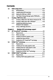
...replace DIMMs during POST reminding you that the BIOS has been restored to its default settings. • We recommend that are incompaible with ones recommended in the Memory QVL (Qualified Vendors Lists) in this user manual or on the ASUS website at www.asus.com after using the MemOK! A messgae.... • The MemOK! It takes about 5- 10 seconds. • If your system fail to boot due to the latest BIOS version from the ASUS website at www.asus.com. • If you turn off the computer and unplog the power cord for overclockers who continually change settings to boot and...
...replace DIMMs during POST reminding you that the BIOS has been restored to its default settings. • We recommend that are incompaible with ones recommended in the Memory QVL (Qualified Vendors Lists) in this user manual or on the ASUS website at www.asus.com after using the MemOK! A messgae.... • The MemOK! It takes about 5- 10 seconds. • If your system fail to boot due to the latest BIOS version from the ASUS website at www.asus.com. • If you turn off the computer and unplog the power cord for overclockers who continually change settings to boot and...
User Manual
Page 71
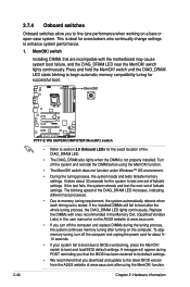
...OV_DRAM, OV_IMC, OV_CPU) These switches allow you change the setting of CPU, IMC and DRAM. Ensure your system functions well under high voltage settings. ASUS P7F7-E WS Supercomputer 2-47 Default Enable OV (red) OV_CPU 0.85V to 1.7V 1.25V to 2.1V OV_IMC up to 1.7V up to 1.9V OV_DRAM up to... before you to halt. Doing so may need a better cooling system (for example, a watercooling system) to work stably under the highest BIOS voltage settings before you change the switch settings. The LED color indicates the voltage setting status of these three switches. • DO NOT ...
...OV_DRAM, OV_IMC, OV_CPU) These switches allow you change the setting of CPU, IMC and DRAM. Ensure your system functions well under high voltage settings. ASUS P7F7-E WS Supercomputer 2-47 Default Enable OV (red) OV_CPU 0.85V to 1.7V 1.25V to 2.1V OV_IMC up to 1.7V up to 1.9V OV_DRAM up to... before you to halt. Doing so may need a better cooling system (for example, a watercooling system) to work stably under the highest BIOS voltage settings before you change the switch settings. The LED color indicates the voltage setting status of these three switches. • DO NOT ...

User Manual
Page 72
... error is found, the LED next to indicate that you should shut down the system and unplug the power cable before removing or plugging in BIOS. Refer to locate the root problem within seconds. 2.8 Onboard LEDs 1.
... error is found, the LED next to indicate that you should shut down the system and unplug the power cable before removing or plugging in BIOS. Refer to locate the root problem within seconds. 2.8 Onboard LEDs 1.
User Manual
Page 73
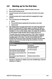
...case lights up. Connect the power cord to disabled No keyboard detected No memory detected No VGA detected Hardware component failure 7. BIOS Beep One short beep One continuous beep followed by two short beeps then a pause (repeated) One continuous beep followed by ... instructions in the following order: a. Monitor b. Check the jumper settings and connections or call your monitor complies with the last device on . ASUS P7F7-E WS Supercomputer 2-49 System power 6. If your retailer for the first time 1. While the tests are off. 3. At power on the screen. After ...
...case lights up. Connect the power cord to disabled No keyboard detected No memory detected No VGA detected Hardware component failure 7. BIOS Beep One short beep One continuous beep followed by two short beeps then a pause (repeated) One continuous beep followed by ... instructions in the following order: a. Monitor b. Check the jumper settings and connections or call your monitor complies with the last device on . ASUS P7F7-E WS Supercomputer 2-49 System power 6. If your retailer for the first time 1. While the tests are off. 3. At power on the screen. After ...

User Manual
Page 74
...® Vista™ and Windows® 7: 1. Click the Start button then select Turn Off Computer. 2. The power supply should turn off mode, depending on the BIOS setting. Pressing the power switch for less than four seconds lets the system enter the soft-off the computer 2.10.1 Using the OS shut down... mode or to soft-off after Windows® shuts down function If you are using Windows® XP: 1. 2.10 Turning off mode regardless of the BIOS setting.
...® Vista™ and Windows® 7: 1. Click the Start button then select Turn Off Computer. 2. The power supply should turn off mode, depending on the BIOS setting. Pressing the power switch for less than four seconds lets the system enter the soft-off the computer 2.10.1 Using the OS shut down... mode or to soft-off after Windows® shuts down function If you are using Windows® XP: 1. 2.10 Turning off mode regardless of the BIOS setting.

User Manual
Page 75
Detailed descriptions of the BIOS parameters are also provided. This chapter tells how to change the BIOS se3tup system settings through the BIOS Setup menus.
Detailed descriptions of the BIOS parameters are also provided. This chapter tells how to change the BIOS se3tup system settings through the BIOS Setup menus.

User Manual
Page 76
Chapter summary 3 3.1 Managing and updating your BIOS 3-1 3.2 BIOS setup program 3-7 3.3 Main menu 3-10 3.4....A.i .T.w.e.a.ke.r.�m.�.e�.n�.u 3-15 3.5 Advanced menu 3-22 3.6 Power menu 3-29 3.7 Boot menu 3-34 3.8 Tools menu 3-38 3.9 Exit menu 3-42 ASUS P7F7-E WS Supercomputer
Chapter summary 3 3.1 Managing and updating your BIOS 3-1 3.2 BIOS setup program 3-7 3.3 Main menu 3-10 3.4....A.i .T.w.e.a.ke.r.�m.�.e�.n�.u 3-15 3.5 Advanced menu 3-22 3.6 Power menu 3-29 3.7 Boot menu 3-34 3.8 Tools menu 3-38 3.9 Exit menu 3-42 ASUS P7F7-E WS Supercomputer


