
User Guide
Page 3
Contents Contents...iii Notices...viii Safety information ix About this guide x P5N64 WS Professional specifications xii Chapter 1: Product introduction 1.1 Welcome 1-1 1.2 Package contents 1-1 1.3 Special features 1-2 1.3.1 Product highlights 1-2 1.3.2 ASUS special features 1-5 1.3.3 ASUS Intelligent Overclocking features 1-8 Chapter 2: Hardware information 2.1 Before you proceed 2-1 ... 2.5 Expansion slots 2-16 2.5.1 Installing an expansion card 2-16 2.5.2 Configuring an expansion card 2-16 2.5.3 Interrupt assignments 2-17 2.5.4 PCI slots 2-18 2.5.5 PCI Express x1 slot 2-18 iii
Contents Contents...iii Notices...viii Safety information ix About this guide x P5N64 WS Professional specifications xii Chapter 1: Product introduction 1.1 Welcome 1-1 1.2 Package contents 1-1 1.3 Special features 1-2 1.3.1 Product highlights 1-2 1.3.2 ASUS special features 1-5 1.3.3 ASUS Intelligent Overclocking features 1-8 Chapter 2: Hardware information 2.1 Before you proceed 2-1 ... 2.5 Expansion slots 2-16 2.5.1 Installing an expansion card 2-16 2.5.2 Configuring an expansion card 2-16 2.5.3 Interrupt assignments 2-17 2.5.4 PCI slots 2-18 2.5.5 PCI Express x1 slot 2-18 iii

User Guide
Page 4
Diagnosis card 2-35 2.8.3 G.P. Diagnosis card check codes 2-36 Chapter 3: Powering up 3.1 Starting up for the first time 3-1 3.2 Turning off the computer 3-2 3.2.1 Using the OS shut down function 3-2 3.2.2 Using the dual function power switch 3-2 Chapter 4: BIOS setup 4.1 Managing and updating your BIOS 4-1 4.1.1 ASUS Update utility 4-1 4.1.2 Creating a bootable floppy disk 4-4 4.1.3 ASUS EZ Flash 2 utility 4-5 4.1.4 AFUDOS utility 4-6 4.1.5 ASUS CrashFree...
Diagnosis card 2-35 2.8.3 G.P. Diagnosis card check codes 2-36 Chapter 3: Powering up 3.1 Starting up for the first time 3-1 3.2 Turning off the computer 3-2 3.2.1 Using the OS shut down function 3-2 3.2.2 Using the dual function power switch 3-2 Chapter 4: BIOS setup 4.1 Managing and updating your BIOS 4-1 4.1.1 ASUS Update utility 4-1 4.1.2 Creating a bootable floppy disk 4-4 4.1.3 ASUS EZ Flash 2 utility 4-5 4.1.4 AFUDOS utility 4-6 4.1.5 ASUS CrashFree...

User Guide
Page 6
...ASUS Contact information 5-6 5.2.7 Other information 5-7 5.3 Software information 5-9 5.3.1 ASUS MyLogo2 5-9 5.3.2 ASUS PC Probe II 5-11 5.3.3 ASUS AI Suite 5-17 5.3.4 ASUS EPU Utility -- AI Gear 3 5-19 5.3.5 ASUS AI Nap 5-21 5.3.6 ASUS Q-Fan 2 5-22 5.3.7 ASUS AI Booster 5-23 5.3.8 AI Audio 2 (SoundMAX® High Definition Audio utility)... 5-24 5.3.9 ASUS... support 6.1 Overview 6-1 Requirements 6-1 6.2 Graphics card setup 6-2 6.2.1 Installing three SLI-ready graphics cards 6-2 6.2.2 Installing two SLI-ready graphics cards 6-5 6.2.3 Installing the device drivers 6-6 6.2.4 ...
...ASUS Contact information 5-6 5.2.7 Other information 5-7 5.3 Software information 5-9 5.3.1 ASUS MyLogo2 5-9 5.3.2 ASUS PC Probe II 5-11 5.3.3 ASUS AI Suite 5-17 5.3.4 ASUS EPU Utility -- AI Gear 3 5-19 5.3.5 ASUS AI Nap 5-21 5.3.6 ASUS Q-Fan 2 5-22 5.3.7 ASUS AI Booster 5-23 5.3.8 AI Audio 2 (SoundMAX® High Definition Audio utility)... 5-24 5.3.9 ASUS... support 6.1 Overview 6-1 Requirements 6-1 6.2 Graphics card setup 6-2 6.2.1 Installing three SLI-ready graphics cards 6-2 6.2.2 Installing two SLI-ready graphics cards 6-5 6.2.3 Installing the device drivers 6-6 6.2.4 ...

User Guide
Page 8
.... However, there is no guarantee that interference will not occur in the Radio Interference Regulations of the Canadian Department of the monitor to the graphics card is subject to the following measures: • Reorient or relocate the receiving antenna. • Increase the separation between the equipment and receiver. • Connect the...
.... However, there is no guarantee that interference will not occur in the Radio Interference Regulations of the Canadian Department of the monitor to the graphics card is subject to the following measures: • Reorient or relocate the receiving antenna. • Increase the separation between the equipment and receiver. • Connect the...

User Guide
Page 10
... The ASUS website provides updated information on the motherboard. • Chapter 3: Powering up This chapter describes the power up NVIDIA® SLI™ graphics cards to avail of the motherboard and the new technology it supports. • Chapter 2: Hardware information This chapter... the following sources for additional information and for product and software updates. 1. It includes description of the jumpers and connectors on ASUS hardware and software products. These documents are also provided. • Chapter 5: Software support This chapter describes the contents of the...
... The ASUS website provides updated information on the motherboard. • Chapter 3: Powering up This chapter describes the power up NVIDIA® SLI™ graphics cards to avail of the motherboard and the new technology it supports. • Chapter 2: Hardware information This chapter... the following sources for additional information and for product and software updates. 1. It includes description of the jumpers and connectors on ASUS hardware and software products. These documents are also provided. • Chapter 5: Software support This chapter describes the contents of the...
User Guide
Page 12
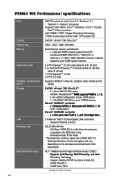
... x PCI 2.2 slots Supports NVIDIA® 3-Way SLI graphics cards (Triple at back I/O - Supports teaming function ASUS WiFi-AP @n - 300 Mbps* IEEE 802.11n (Draft) and backwards compatible with IEEE 802.11b/g - P5N64 WS Professional specifications CPU Chipset System bus Memory Expansion slots Scalable Link ...Core™ 2 Quad / Core™ 2 Duo processor Intel® EM64T / EIST / Hyper-Threading Technology * Refer to www.asus.com for up to 2 PATA devices Marvell® 88SE6121 controller - �2��x��E���x���...
... x PCI 2.2 slots Supports NVIDIA® 3-Way SLI graphics cards (Triple at back I/O - Supports teaming function ASUS WiFi-AP @n - 300 Mbps* IEEE 802.11n (Draft) and backwards compatible with IEEE 802.11b/g - P5N64 WS Professional specifications CPU Chipset System bus Memory Expansion slots Scalable Link ...Core™ 2 Quad / Core™ 2 Duo processor Intel® EM64T / EIST / Hyper-Threading Technology * Refer to www.asus.com for up to 2 PATA devices Marvell® 88SE6121 controller - �2��x��E���x���...

User Guide
Page 13
...at 1MHz increment Overclocking Protection: - P5N64 WS Professional specifications IEEE 1394 USB AI Lifestyle Unique Features Other Features ASUS Exclusive Overclocking Features VIA VT6308S 1394a ...ASUS 3rd Generation 8-Phase Power Design - ASUS SASsaby cards support ASUS Quiet Thermal Solution: - ASUS O.C. ASUS Stack Cool 2 ASUS EZ DIY: - ASUS CrashFree BIOS 3 - vCore: Adjustable CPU voltage at 1MHz increment - vChipset (N.B.): 25-step DRAM voltage control - ASUS Fanless Design: Pure Copper Heat-pipe solution - one at midboard; ASUS Q-Connector - ASUS AI Nap ASUS...
...at 1MHz increment Overclocking Protection: - P5N64 WS Professional specifications IEEE 1394 USB AI Lifestyle Unique Features Other Features ASUS Exclusive Overclocking Features VIA VT6308S 1394a ...ASUS 3rd Generation 8-Phase Power Design - ASUS SASsaby cards support ASUS Quiet Thermal Solution: - ASUS O.C. ASUS Stack Cool 2 ASUS EZ DIY: - ASUS CrashFree BIOS 3 - vCore: Adjustable CPU voltage at 1MHz increment - vChipset (N.B.): 25-step DRAM voltage control - ASUS Fanless Design: Pure Copper Heat-pipe solution - one at midboard; ASUS Q-Connector - ASUS AI Nap ASUS...
User Guide
Page 17
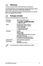
... ATA signal cable for 6 devices Serial ATA power cable for buying an ASUS® P5N64 WS Professional motherboard! Thank you start installing the motherboard, and hardware devices on ...ASUS P5N64 WS Professional 1 x 2��-p�o��rt�U��S�B 1 p��o���r�t��I /O shield ASUS SLI bridge 3-Way SLI bridge 1 x ASUS Q-Connector Kit (USB, 1394, system panel; Diagnosis card (Retail version only) 2 x WiFi-AP @n omni-directional antennae ASUS motherboard support DVD User guide ASUS WiFi...
... ATA signal cable for 6 devices Serial ATA power cable for buying an ASUS® P5N64 WS Professional motherboard! Thank you start installing the motherboard, and hardware devices on ...ASUS P5N64 WS Professional 1 x 2��-p�o��rt�U��S�B 1 p��o���r�t��I /O shield ASUS SLI bridge 3-Way SLI bridge 1 x ASUS Q-Connector Kit (USB, 1394, system panel; Diagnosis card (Retail version only) 2 x WiFi-AP @n omni-directional antennae ASUS motherboard support DVD User guide ASUS WiFi...
User Guide
Page 20
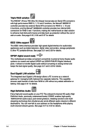
... motherboard provides convenient connectivity to analog format and keeps the best signal quality. High Definition Audio Enjoy high-end sound quality on your partners on cards. Dual Gigabit LAN solution The integrated dual Gigabit LAN design allows a PC to different destinations. The onboard 8-channel HD audio (High Definition Audio, previously codenamed...
... motherboard provides convenient connectivity to analog format and keeps the best signal quality. High Definition Audio Enjoy high-end sound quality on your partners on cards. Dual Gigabit LAN solution The integrated dual Gigabit LAN design allows a PC to different destinations. The onboard 8-channel HD audio (High Definition Audio, previously codenamed...
User Guide
Page 22
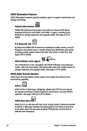
... enhances the overclocking capability. ASUS SASsaby cards support This motherboard is a fan-less and zero-noise cooling solution offered exclusively by ASUS. See page 2-19 for storage expansion and upgrade needs. ASUS Workstation Features ASUS Workstation features provide complete support to ensure quiet, cool and efficient operation. Onboard SAS interface P5N64 WS Professional provides users with two...
... enhances the overclocking capability. ASUS SASsaby cards support This motherboard is a fan-less and zero-noise cooling solution offered exclusively by ASUS. See page 2-19 for storage expansion and upgrade needs. ASUS Workstation Features ASUS Workstation features provide complete support to ensure quiet, cool and efficient operation. Onboard SAS interface P5N64 WS Professional provides users with two...
User Guide
Page 26
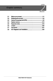
Chapter summary 2 2.1 Before you proceed 2-1 2.2 Motherboard overview 2-2 2.3 Central Processing Unit (CPU 2-6 2.4 System memory 2-13 2.5 Expansion slots 2-16 2.6 Jumper 2-20 2.7 Connectors 2-21 2.8 G.P. Diagnosis card installation 2-35 ASUS P5N64 WS Professional
Chapter summary 2 2.1 Before you proceed 2-1 2.2 Motherboard overview 2-2 2.3 Central Processing Unit (CPU 2-6 2.4 System memory 2-13 2.5 Expansion slots 2-16 2.6 Jumper 2-20 2.7 Connectors 2-21 2.8 G.P. Diagnosis card installation 2-35 ASUS P5N64 WS Professional

User Guide
Page 42
...software drivers for details. 2-16 Chapter 2: Hardware information Otherwise, conflicts will arise between the two PCI groups, making the system unstable and the card inoperable. Failure to do not need to the tables on shared slots, ensure that the drivers support "Share IRQ" or that they support. ... the system unit cover (if your motherboard is completely seated on the system and change the necessary BIOS settings, if any. Align the card connector with the screw you may cause you intend to the table on BIOS setup. 2. Assign an IRQ to unplug the power cord before...
...software drivers for details. 2-16 Chapter 2: Hardware information Otherwise, conflicts will arise between the two PCI groups, making the system unstable and the card inoperable. Failure to do not need to the tables on shared slots, ensure that the drivers support "Share IRQ" or that they support. ... the system unit cover (if your motherboard is completely seated on the system and change the necessary BIOS settings, if any. Align the card connector with the screw you may cause you intend to the table on BIOS setup. 2. Assign an IRQ to unplug the power cord before...

User Guide
Page 44
... with a maximum speed of the slots. 2.5.5 PCI Express x1 slot This motherboard supports PCI Express x1 network cards, SCSI cards and other cards that comply with PCI specifications. Universal PCIe x16_4 slot (white @ x8 link) PCIe 2.0 x16_3 slot (blue @ x16 link) PCI_2 slot Universal PCIe x16_2 slot (black @ ... to a PCIe x1 slot prior to the figure below for the location of x16 (black) and x8 (white) link. 2.5.4 PCI slots The PCI slots support cards such as a LAN card, SCSI card, USB card, and other cards that comply with the PCI Express specifications.
... with a maximum speed of the slots. 2.5.5 PCI Express x1 slot This motherboard supports PCI Express x1 network cards, SCSI cards and other cards that comply with PCI specifications. Universal PCIe x16_4 slot (white @ x8 link) PCIe 2.0 x16_3 slot (blue @ x16 link) PCI_2 slot Universal PCIe x16_2 slot (black @ ... to a PCIe x1 slot prior to the figure below for the location of x16 (black) and x8 (white) link. 2.5.4 PCI slots The PCI slots support cards such as a LAN card, SCSI card, USB card, and other cards that comply with the PCI Express specifications.

User Guide
Page 45
... sufficient power when running SLI™ mode. For SASsaby 1064E, install the card to get better performance. • In SLI™ mode, use any of the PCIe x16 slots (blue, black or white). ASUS P5N64 WS Professional 2-19 See page 2-32 for details. • Connect a chassis ...fan to the motherboard connector labeled CHA_FAN1/2/3 when using multiple graphics cards for SAS hard disk drive expansion. For SASsaby M, install the card to any of the PCIe 2.0 slots (...
... sufficient power when running SLI™ mode. For SASsaby 1064E, install the card to get better performance. • In SLI™ mode, use any of the PCIe x16 slots (blue, black or white). ASUS P5N64 WS Professional 2-19 See page 2-32 for details. • Connect a chassis ...fan to the motherboard connector labeled CHA_FAN1/2/3 when using multiple graphics cards for SAS hard disk drive expansion. For SASsaby M, install the card to any of the PCIe 2.0 slots (...
User Guide
Page 52
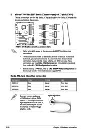
... RSATA_TXP2 GND P5B GND RSATA_TXP5 RSATA_TXN5 GND RSATA_RXP5 RSATA_RXN5 GND SSATAAT5 AR1SATA_TGXNPD6 RSATA_TXN6 GND RSATA_RXP6 RSATA_RXN6 GND SATASA2TA6 R P5N64 WS PRO GND RSATA_TXP3 RSATA_TXN3 GND RSATA_RXP3 RSATA_RXN3 GND SATA3 GND RSATA_TXP4 RSATA_TXN4 GND SATA3 RSATA_RXP4 RSATA_RXN4 GND SATA4 SATA4 GND ...optical disk drives. Or you intend to create a Serial ATA RAID set , refer to avoid mechanical conflict with huge graphics cards. right angle side 2-26 Chapter 2: Hardware information Serial ATA hard disk drive connection Connector SATA 1/2 SATA 3/4 SATA 5/6 Color...
... RSATA_TXP2 GND P5B GND RSATA_TXP5 RSATA_TXN5 GND RSATA_RXP5 RSATA_RXN5 GND SSATAAT5 AR1SATA_TGXNPD6 RSATA_TXN6 GND RSATA_RXP6 RSATA_RXN6 GND SATASA2TA6 R P5N64 WS PRO GND RSATA_TXP3 RSATA_TXN3 GND RSATA_RXP3 RSATA_RXN3 GND SATA3 GND RSATA_TXP4 RSATA_TXN4 GND SATA3 RSATA_RXP4 RSATA_RXN4 GND SATA4 SATA4 GND ...optical disk drives. Or you intend to create a Serial ATA RAID set , refer to avoid mechanical conflict with huge graphics cards. right angle side 2-26 Chapter 2: Hardware information Serial ATA hard disk drive connection Connector SATA 1/2 SATA 3/4 SATA 5/6 Color...

User Guide
Page 55
... from sound sources such as a CD-ROM, TV tuner, or MPEG card. Serial port connector (10-1 pin COM1) This connector is for a serial (COM) port. Left Audio Channel GND GND Right Audio Channel 7. COM1 PIN 1 P5N64 WS PRO P5N64 WS Professional Serial port2(COM1) connector ASUS P5N64 WS Professional 2-29 Optical drive audio connector (4-pin CD) These connectors allow...
... from sound sources such as a CD-ROM, TV tuner, or MPEG card. Serial port connector (10-1 pin COM1) This connector is for a serial (COM) port. Left Audio Channel GND GND Right Audio Channel 7. COM1 PIN 1 P5N64 WS PRO P5N64 WS Professional Serial port2(COM1) connector ASUS P5N64 WS Professional 2-29 Optical drive audio connector (4-pin CD) These connectors allow...

User Guide
Page 58
...P5N64 WS PRO GND GND GND GND +3 Volts +12 Volts +12 Volts +5V Standby Power OK GND PIN 1 +5 Volts GND +5 Volts GND +3 Volts +3 Volts PIN 1 GND +5 Volts +5 Volts +5 Volts -5 Volts GND GND GND PSON# GND -12 Volts +3 Volts P5N64 WS... Professional ATX power connectors • For a fully configured system, we recommend that complies with ATX 12 V Specification 2.0 (or later version) and provides a minimum power of a PSU with a higher power output is inadequate. • If you want to the Recommended Power Supply Wattage Calculator at http://support.asus...PCI Express x16 cards, use a ...
...P5N64 WS PRO GND GND GND GND +3 Volts +12 Volts +12 Volts +5V Standby Power OK GND PIN 1 +5 Volts GND +5 Volts GND +3 Volts +3 Volts PIN 1 GND +5 Volts +5 Volts +5 Volts -5 Volts GND GND GND PSON# GND -12 Volts +3 Volts P5N64 WS... Professional ATX power connectors • For a fully configured system, we recommend that complies with ATX 12 V Specification 2.0 (or later version) and provides a minimum power of a PSU with a higher power output is inadequate. • If you want to the Recommended Power Supply Wattage Calculator at http://support.asus...PCI Express x16 cards, use a ...

User Guide
Page 61
... (20-1 pin TPM) on the connector completely. P5N64 WS PRO P5N64 WS Professional TPM connector 2. Reset Button. With the LEDs of the diagnosis card facing to avoid electrical shock hazard. 1. 2.8 G.P. ASUS P5N64 WS Professional 2-35 Card connector 2.8.2 Installing G.P. Press to turn ON or OFF the computer. Diagnosis card layout LED 0 and 1 Power Switch. Diagnosis card Make sure to restart the computer. Diagnosis...
... (20-1 pin TPM) on the connector completely. P5N64 WS PRO P5N64 WS Professional TPM connector 2. Reset Button. With the LEDs of the diagnosis card facing to avoid electrical shock hazard. 1. 2.8 G.P. ASUS P5N64 WS Professional 2-35 Card connector 2.8.2 Installing G.P. Press to turn ON or OFF the computer. Diagnosis card layout LED 0 and 1 Power Switch. Diagnosis card Make sure to restart the computer. Diagnosis...

User Guide
Page 62
You may also install the G.P. Diagnosis card check codes D0 Initiate chip D1 Enable IO device for bootlock D2 Check and wake up AP 0A Initiate KBC8042 0B Detect PS2 mouse 0C ... 10 Resume from S1 30 Resume from S3 40 Resume from S4 00 Leave BIOS and pass control to OS 2-36 Chapter 2: Hardware information Diagnosis card via a bundled 90degree TPM adaptor for memory detection and sizing D4 Memory test D5 Copy BIOS from ROM to RAM C0 Early CPU initiation C5...
You may also install the G.P. Diagnosis card check codes D0 Initiate chip D1 Enable IO device for bootlock D2 Check and wake up AP 0A Initiate KBC8042 0B Detect PS2 mouse 0C ... 10 Resume from S1 30 Resume from S3 40 Resume from S4 00 Leave BIOS and pass control to OS 2-36 Chapter 2: Hardware information Diagnosis card via a bundled 90degree TPM adaptor for memory detection and sizing D4 Memory test D5 Copy BIOS from ROM to RAM C0 Early CPU initiation C5...

User Guide
Page 173
NVIDIA® SLI™ technology support This chapter tells how to set up NVIDIA® SLI™ graphics cards to avail of NVIDIA's 6 Chapter 6: Multi-Video Processing technology.
NVIDIA® SLI™ technology support This chapter tells how to set up NVIDIA® SLI™ graphics cards to avail of NVIDIA's 6 Chapter 6: Multi-Video Processing technology.


