Asus P5n32 Sli Motherboard - P5N32ESLI
Asus P5n32 Sli Motherboard
Related Manual Pages


Related Videos

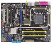
Asus P5N32-E SLI motherboard
Duration: 2:33
Total Views: 13
Duration: 2:33
Total Views: 13
Similar Questions

I Would Like To Have A Bios Beep Codes For Model M2n4 Sli. Asus Motherboard.
(Posted by eustaquio3x 8 years ago)
Where Is My Model Number On My Motherboard?
Where is my model number on my motherboard?
Where is my model number on my motherboard?
(Posted by johnfiliceiiii 11 years ago)

Where Do I Find A Motherboard Manual?
I need the manual for an Asus M3A78-EMH HDMI Socket AM2+AMD 780G/Hybrid CrossFireX/HDMI/A&V&...
I need the manual for an Asus M3A78-EMH HDMI Socket AM2+AMD 780G/Hybrid CrossFireX/HDMI/A&V&...
(Posted by ke7hhw 12 years ago)