User Guide
Page 2
...LOSS OF USE OR DATA, INTERRUPTION OF BUSINESS AND THE LIKE), EVEN IF ASUS HAS BEEN ADVISED OF THE POSSIBILITY OF SUCH DAMAGES ARISING FROM ANY DEFECT OR ERROR IN THIS MANUAL OR PRODUCT. ii SPECIFICATIONS AND INFORMATION CONTAINED IN THIS MANUAL ARE FURNISHED FOR INFORMATIONAL USE ONLY, AND... ARE SUBJECT TO CHANGE AT ANY TIME WITHOUT NOTICE, AND SHOULD NOT BE CONSTRUED AS A COMMITMENT BY ASUS. ASUS ASSUMES NO RESPONSIBILITY OR LIABILITY FOR ANY ERRORS...
...LOSS OF USE OR DATA, INTERRUPTION OF BUSINESS AND THE LIKE), EVEN IF ASUS HAS BEEN ADVISED OF THE POSSIBILITY OF SUCH DAMAGES ARISING FROM ANY DEFECT OR ERROR IN THIS MANUAL OR PRODUCT. ii SPECIFICATIONS AND INFORMATION CONTAINED IN THIS MANUAL ARE FURNISHED FOR INFORMATIONAL USE ONLY, AND... ARE SUBJECT TO CHANGE AT ANY TIME WITHOUT NOTICE, AND SHOULD NOT BE CONSTRUED AS A COMMITMENT BY ASUS. ASUS ASSUMES NO RESPONSIBILITY OR LIABILITY FOR ANY ERRORS...

User Guide
Page 3
Contents Notices vi Safety information vii About this guide viii P5MT Series specifications summary x Chapter 1: Product introduction 1.1 Welcome 1-1 1.2 Package contents 1-1 1.3 Special features 1-2 1.3.1 Product highlights 1-2 1.3.2 Innovative ASUS features 1-4 Chapter 2: Hardware information 2.1 Before you proceed 2-1 2.2 Motherboard overview 2-2 2.2.1 Placement direction 2-2 2.2.2 Screw holes 2-2 2.2.3 Motherboard layouts 2-3 2.2.4 Layout contents 2-5 2.3 Central Processing Unit (CPU 2-7 2.3.1 Installing the CPU 2-7 2.3.2 Installing ...
Contents Notices vi Safety information vii About this guide viii P5MT Series specifications summary x Chapter 1: Product introduction 1.1 Welcome 1-1 1.2 Package contents 1-1 1.3 Special features 1-2 1.3.1 Product highlights 1-2 1.3.2 Innovative ASUS features 1-4 Chapter 2: Hardware information 2.1 Before you proceed 2-1 2.2 Motherboard overview 2-2 2.2.1 Placement direction 2-2 2.2.2 Screw holes 2-2 2.2.3 Motherboard layouts 2-3 2.2.4 Layout contents 2-5 2.3 Central Processing Unit (CPU 2-7 2.3.1 Installing the CPU 2-7 2.3.2 Installing ...

User Guide
Page 11
... MHz/64-bit slot (PCI-X 1.0) (supports Zero-Channel RAID card, colored green on the next page) xi P5MT Series specifications summary CPU Chipset Front Side Bus Memory Expansion slots* Storage P5MT P5MT/SCSI LGA775 socket for Intel® Pentium® 4 processor Compatible with Intel® PCG 05B/05A and 04B... PCI-X slot is occupied, the PCI-X frequency is 66 MHz. (continued on P5MT/SCSI model) 1 x PCI-X 100 MHz/64-bit slot (PCI-X 1.0) 1 x PCI 33 MHz/32-bit/5V slot (PCI 2.3) 1 x mini-PCI socket for ASUS® Server Management Board Intel® ICH7R Southbridge supports: - 2 x Ultra ...
... MHz/64-bit slot (PCI-X 1.0) (supports Zero-Channel RAID card, colored green on the next page) xi P5MT Series specifications summary CPU Chipset Front Side Bus Memory Expansion slots* Storage P5MT P5MT/SCSI LGA775 socket for Intel® Pentium® 4 processor Compatible with Intel® PCG 05B/05A and 04B... PCI-X slot is occupied, the PCI-X frequency is 66 MHz. (continued on P5MT/SCSI model) 1 x PCI-X 100 MHz/64-bit slot (PCI-X 1.0) 1 x PCI 33 MHz/32-bit/5V slot (PCI 2.3) 1 x mini-PCI socket for ASUS® Server Management Board Intel® ICH7R Southbridge supports: - 2 x Ultra ...

User Guide
Page 12
xii P5MT Series specifications summary Graphics ATI® RAGE-XL PCI-based VGA controller LAN LAN 1: Broadcom BCM5721 Gigabit LAN controller LAN 2: Broadcom BCM5721 Gigabit LAN controller Complies with PCI Express 1.0a specifications USB Intel® ICH7R Southbridge supports: - 4 USB 2.0 ports (2 on the rear panel, 2 on the front panel) Special features ASUS Smart Fan ASUS CrashFree...
xii P5MT Series specifications summary Graphics ATI® RAGE-XL PCI-based VGA controller LAN LAN 1: Broadcom BCM5721 Gigabit LAN controller LAN 2: Broadcom BCM5721 Gigabit LAN controller Complies with PCI Express 1.0a specifications USB Intel® ICH7R Southbridge supports: - 4 USB 2.0 ports (2 on the rear panel, 2 on the front panel) Special features ASUS Smart Fan ASUS CrashFree...

User Guide
Page 16
... with 1066/800/533 MHz Front Side Bus (FSB). Intel® EM64T The motherboard supports Intel® Pentium® 4 CPUs with existing PCI or PCI-X specifications. The MCH provides the processor, dual-channel DDR2-533/667 memory, and PCI Express interfaces. The dual-channel memory architecture doubles the bandwidth of your...
... with 1066/800/533 MHz Front Side Bus (FSB). Intel® EM64T The motherboard supports Intel® Pentium® 4 CPUs with existing PCI or PCI-X specifications. The MCH provides the processor, dual-channel DDR2-533/667 memory, and PCI Express interfaces. The dual-channel memory architecture doubles the bandwidth of your...

User Guide
Page 17
... 2.0 is onboard to support one 68-pin Ultra320 SCSI connector, that supports an optional Zero-Channel RAID card. ASUS P5MT Series 1-3 Ultra320 SCSI feature (P5MT/SCSI model only) The LSI53C1020A PCI-X SCSI controller is backward compatible with lower pin count, reduced voltage requirement,... throughput close to a fast 480 Mbps on USB 2.0. The SATA specification allows for thinner, more flexible cables with USB 1.1. USB 2.0 technology The motherboard implements the Universal Serial Bus (USB) 2.0 specification, dramatically increasing the connection speed from the 12 Mbps bandwidth on USB...
... 2.0 is onboard to support one 68-pin Ultra320 SCSI connector, that supports an optional Zero-Channel RAID card. ASUS P5MT Series 1-3 Ultra320 SCSI feature (P5MT/SCSI model only) The LSI53C1020A PCI-X SCSI controller is backward compatible with lower pin count, reduced voltage requirement,... throughput close to a fast 480 Mbps on USB 2.0. The SATA specification allows for thinner, more flexible cables with USB 1.1. USB 2.0 technology The motherboard implements the Universal Serial Bus (USB) 2.0 specification, dramatically increasing the connection speed from the 12 Mbps bandwidth on USB...
User Guide
Page 37
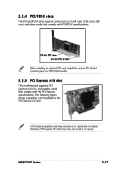
... I /O cards may run at x1 speed due to chipset limitation. ASUS P5MT Series 2-17 2.5.4 PCI/PCI-X slots The PCI and PCI-X slots support cards such as a LAN card, SCSI card, USB card, and other cards that comply with the PCI Express specifications. A PCI Express graphics card may only run only at x8 or... x4 speed. PCI Express I /O, and graphic cards that comply with PCI/PCI-X specifications. 32-bit PCI slot 64-bit PCI-X slot When installing an optional ZCR card, install the card on PCI_X2 slot (colored green on the PCI ...
... I /O cards may run at x1 speed due to chipset limitation. ASUS P5MT Series 2-17 2.5.4 PCI/PCI-X slots The PCI and PCI-X slots support cards such as a LAN card, SCSI card, USB card, and other cards that comply with the PCI Express specifications. A PCI Express graphics card may only run only at x8 or... x4 speed. PCI Express I /O, and graphic cards that comply with PCI/PCI-X specifications. 32-bit PCI slot 64-bit PCI-X slot When installing an optional ZCR card, install the card on PCI_X2 slot (colored green on the PCI ...

User Guide
Page 46
...-1 pin USB34) This connector is purchased separately. ® USB+5V USB_P3USB_P3+ GND NC USB+5V USB_P2USB_P2+ GND 2-26 Chapter 2: Hardware information LAN2 USB34 P5MT Series USB 2.0 connector The USB port module is for USB 2.0 ports. Connect the USB module cable to this connector, then install the module to a ... or the SATA connectors cause this LED to light up to the hard disk activity LED. This USB connector complies with USB 2.0 specification that supports up . The read or write activities of the system chassis. ® NC ADD_IN_CARD_ACT# ADD_IN_CARD_ACT# NC 4 .
...-1 pin USB34) This connector is purchased separately. ® USB+5V USB_P3USB_P3+ GND NC USB+5V USB_P2USB_P2+ GND 2-26 Chapter 2: Hardware information LAN2 USB34 P5MT Series USB 2.0 connector The USB port module is for USB 2.0 ports. Connect the USB module cable to this connector, then install the module to a ... or the SATA connectors cause this LED to light up to the hard disk activity LED. This USB connector complies with USB 2.0 specification that supports up . The read or write activities of the system chassis. ® NC ADD_IN_CARD_ACT# ADD_IN_CARD_ACT# NC 4 .

User Guide
Page 50
...Volts Ground PSON# Ground Ground Ground -5 Volts +5 Volts +5 Volts +5 Volts Ground +12V DC +12V DC +12V DC +12V DC 2-30 P5MT Series ATX power connectors Chapter 2: Hardware information 12. The power supply plugs are for SSI power supply plugs. Remove this cover when using a PSU ...® PSU_I2CCLK PSU_I2CDATA NC GND +3.3V Remote Sense LAN2 PSUSMB1 P5MT Series Power supply SMBus connector 1 3 . Find the proper orientation and push down firmly until the connectors completely fit. • Use of an SSI 12 V Specification 2.0-compliant power supply unit (PSU) that provides a minimum power ...
...Volts Ground PSON# Ground Ground Ground -5 Volts +5 Volts +5 Volts +5 Volts Ground +12V DC +12V DC +12V DC +12V DC 2-30 P5MT Series ATX power connectors Chapter 2: Hardware information 12. The power supply plugs are for SSI power supply plugs. Remove this cover when using a PSU ...® PSU_I2CCLK PSU_I2CDATA NC GND +3.3V Remote Sense LAN2 PSUSMB1 P5MT Series Power supply SMBus connector 1 3 . Find the proper orientation and push down firmly until the connectors completely fit. • Use of an SSI 12 V Specification 2.0-compliant power supply unit (PSU) that provides a minimum power ...

User Guide
Page 70
4.2.4 Menu items The highlighted item on the menu bar displays the specific items for the menu items. If an item is userconfigurable, you can change the value of a field, select it then press to display a list of ...
4.2.4 Menu items The highlighted item on the menu bar displays the specific items for the menu items. If an item is userconfigurable, you can change the value of a field, select it then press to display a list of ...

User Guide
Page 74
... data transfer from and to the device occurs one sector at a time if the device supports multi-sector transfer feature. Select [CDROM] if you are specifically configuring a CD-ROM drive. Select [ARMD] (ATAPI Removable Media Device) if your device is either a ZIP, LS-120, or MO drive. Configuration options: [Auto] [Disabled...
... data transfer from and to the device occurs one sector at a time if the device supports multi-sector transfer feature. Select [CDROM] if you are specifically configuring a CD-ROM drive. Select [ARMD] (ATAPI Removable Media Device) if your device is either a ZIP, LS-120, or MO drive. Configuration options: [Auto] [Disabled...

User Guide
Page 75
Change Option F1 General Help F10 Save and Exit ESC Exit v02.58 (C)Copyright 1985-2004, American Megatrends, Inc. ASUS P5MT Series 4-17 Main AMIBIOS Version : 08.00.11 Build Date : 06/14/05 BIOS SETUP UTILITY Processor Type Speed Count : Genuine ... +- AMI BIOS Displays the auto-detected BIOS information. 4.3.6 System Information This menu gives you an overview of the general system specifications. Processor Displays the auto-detected CPU specification. System Memory Displays the auto-detected total system memory. The BIOS automatically detects the items in this menu.
Change Option F1 General Help F10 Save and Exit ESC Exit v02.58 (C)Copyright 1985-2004, American Megatrends, Inc. ASUS P5MT Series 4-17 Main AMIBIOS Version : 08.00.11 Build Date : 06/14/05 BIOS SETUP UTILITY Processor Type Speed Count : Genuine ... +- AMI BIOS Displays the auto-detected BIOS information. 4.3.6 System Information This menu gives you an overview of the general system specifications. Processor Displays the auto-detected CPU specification. System Memory Displays the auto-detected total system memory. The BIOS automatically detects the items in this menu.

User Guide
Page 82
...] Allows you to set or disable the PCI Express Graphic port. Configuration options: [Disabled] [2 USB Ports] [4 USB Ports] USB 2.0 Controller [Enabled] Allows you to enable a specific number of the graphics controller to the DDR SDRAM. Advanced BIOS SETUP UTILITY South Bridge Chipset Configuration USB Functions USB 2.0 Controller [4 USB Ports] [Enabled] PCIE...
...] Allows you to set or disable the PCI Express Graphic port. Configuration options: [Disabled] [2 USB Ports] [4 USB Ports] USB 2.0 Controller [Enabled] Allows you to enable a specific number of the graphics controller to the DDR SDRAM. Advanced BIOS SETUP UTILITY South Bridge Chipset Configuration USB Functions USB 2.0 Controller [4 USB Ports] [Enabled] PCIE...

User Guide
Page 85
... [PCI Device], the specific IRQ is reserved for use of PCI/PnP devices. When set to the PCI VGA card even if requested. When set to [No], BIOS does not assign an IRQ to [Reserved], the IRQ is free for legacy devices. Configuration options: [PCI Device] [Reserved] ASUS P5MT Series 4-27 The menu...
... [PCI Device], the specific IRQ is reserved for use of PCI/PnP devices. When set to the PCI VGA card even if requested. When set to [No], BIOS does not assign an IRQ to [Reserved], the IRQ is free for legacy devices. Configuration options: [PCI Device] [Reserved] ASUS P5MT Series 4-27 The menu...

User Guide
Page 86
.... Select Screen Select Item +- Select Screen Select Item +- Select an item then press to Enabled, the ACPI APIC table pointer is included in the Application-Specific Integrated Circuit (ASIC). When set to display the configuration options. Power Management [Enabled] Allows you to change the settings for the ACPI and Advanced Power...
.... Select Screen Select Item +- Select Screen Select Item +- Select an item then press to Enabled, the ACPI APIC table pointer is included in the Application-Specific Integrated Circuit (ASIC). When set to display the configuration options. Power Management [Enabled] Allows you to change the settings for the ACPI and Advanced Power...

User Guide
Page 89
...options: [Disabled] [Enabled] Power On By PS/2 Mouse [Disabled] When set to [Enabled], this parameter allows you to use specific keys on the keyboard to turn on the system. Use the down arrow key to display the detected temperatures. Smart Fan Control ... Fan1 Speed Rear Fan2 Speed Power BIOS SETUP UTILITY [49ºC/120ºF] [39ºC/102ºF] [5038RPM] [5045RPM] [N/A] [N/A] [N/A] [N/A] CPU1 Temperature. ASUS NCLV-D2 Series 4-31 CPU1 Temperature [xxxºC/xxxºF] MB Temperature [xxxºC/xxxºF] The onboard hardware monitor automatically detects and displays the...
...options: [Disabled] [Enabled] Power On By PS/2 Mouse [Disabled] When set to [Enabled], this parameter allows you to use specific keys on the keyboard to turn on the system. Use the down arrow key to display the detected temperatures. Smart Fan Control ... Fan1 Speed Rear Fan2 Speed Power BIOS SETUP UTILITY [49ºC/120ºF] [39ºC/102ºF] [5038RPM] [5045RPM] [N/A] [N/A] [N/A] [N/A] CPU1 Temperature. ASUS NCLV-D2 Series 4-31 CPU1 Temperature [xxxºC/xxxºF] MB Temperature [xxxºC/xxxºF] The onboard hardware monitor automatically detects and displays the...

User Guide
Page 132
... arrays, and arrange the sequence of an adapter. otherwise, press to open the A d a p t e r P r o p e r t i e s screen; Property Adapter PCI Bus Dev/Func Boot Order Description Identifies the specific family of LSI Logic Host Adapters. Select the adapter from the list (1020/1030), then press . The screen displays the selected adapter's properties.
... arrays, and arrange the sequence of an adapter. otherwise, press to open the A d a p t e r P r o p e r t i e s screen; Property Adapter PCI Bus Dev/Func Boot Order Description Identifies the specific family of LSI Logic Host Adapters. Select the adapter from the list (1020/1030), then press . The screen displays the selected adapter's properties.
