User Guide
Page 2
... or may be registered trademarks or copyrights of alteration is defaced or missing. or (2) the serial number of ASUSTeK COMPUTER INC. ("ASUS"). ASUS PROVIDES THIS MANUAL "AS IS" WITHOUT WARRANTY OF ANY KIND, EITHER EXPRESS OR IMPLIED, INCLUDING BUT NOT LIMITED TO THE IMPLIED WARRANTIES... OR CONDITIONS OF MERCHANTABILITY OR FITNESS FOR A PARTICULAR PURPOSE. SPECIFICATIONS AND INFORMATION CONTAINED IN THIS MANUAL ARE FURNISHED FOR INFORMATIONAL USE ONLY, AND ARE SUBJECT TO CHANGE AT ANY TIME WITHOUT NOTICE, AND...
... or may be registered trademarks or copyrights of alteration is defaced or missing. or (2) the serial number of ASUSTeK COMPUTER INC. ("ASUS"). ASUS PROVIDES THIS MANUAL "AS IS" WITHOUT WARRANTY OF ANY KIND, EITHER EXPRESS OR IMPLIED, INCLUDING BUT NOT LIMITED TO THE IMPLIED WARRANTIES... OR CONDITIONS OF MERCHANTABILITY OR FITNESS FOR A PARTICULAR PURPOSE. SPECIFICATIONS AND INFORMATION CONTAINED IN THIS MANUAL ARE FURNISHED FOR INFORMATIONAL USE ONLY, AND ARE SUBJECT TO CHANGE AT ANY TIME WITHOUT NOTICE, AND...

User Guide
Page 3
Contents Notices vi Safety information vii About this guide viii P5MT Series specifications summary x Chapter 1: Product introduction 1.1 Welcome 1-1 1.2 Package contents 1-1 1.3 Special features 1-2 1.3.1 Product highlights 1-2 1.3.2 Innovative ASUS features 1-4 Chapter 2: Hardware information 2.1 Before you proceed 2-1 2.2 Motherboard overview 2-2 2.2.1 Placement direction 2-2 2.2.2 Screw holes 2-2 2.2.3 Motherboard layouts 2-3 2.2.4 Layout contents 2-5 2.3 Central Processing Unit (CPU 2-7 2.3.1 Installing the CPU 2-7 2.3.2 Installing ...
Contents Notices vi Safety information vii About this guide viii P5MT Series specifications summary x Chapter 1: Product introduction 1.1 Welcome 1-1 1.2 Package contents 1-1 1.3 Special features 1-2 1.3.1 Product highlights 1-2 1.3.2 Innovative ASUS features 1-4 Chapter 2: Hardware information 2.1 Before you proceed 2-1 2.2 Motherboard overview 2-2 2.2.1 Placement direction 2-2 2.2.2 Screw holes 2-2 2.2.3 Motherboard layouts 2-3 2.2.4 Layout contents 2-5 2.3 Central Processing Unit (CPU 2-7 2.3.1 Installing the CPU 2-7 2.3.2 Installing ...

User Guide
Page 11
... model: When one PCI-X slot is occupied, the PCI-X frequency is 100 MHz. P5MT Series specifications summary CPU Chipset Front Side Bus Memory Expansion slots* Storage P5MT P5MT/SCSI LGA775 socket for ASUS® Server Management Board Intel® ICH7R Southbridge supports: - 2 x Ultra ATA 100/66/33 hard disk drives ...or IMSM (RAID 0, RAID 1, RAID 10, and software RAID 5), or the LSI Logic Embedded SATA RAID controller (RAID 0, RAID 1, RAID 10) P5MT storage + LSI53C1020A PCI-X SCSI controller supports: - 1 x Ultra-320 SCSI channel with Intel® PCG 05B/05A and 04B/04A and the latest ...
... model: When one PCI-X slot is occupied, the PCI-X frequency is 100 MHz. P5MT Series specifications summary CPU Chipset Front Side Bus Memory Expansion slots* Storage P5MT P5MT/SCSI LGA775 socket for ASUS® Server Management Board Intel® ICH7R Southbridge supports: - 2 x Ultra ATA 100/66/33 hard disk drives ...or IMSM (RAID 0, RAID 1, RAID 10, and software RAID 5), or the LSI Logic Embedded SATA RAID controller (RAID 0, RAID 1, RAID 10) P5MT storage + LSI53C1020A PCI-X SCSI controller supports: - 1 x Ultra-320 SCSI channel with Intel® PCG 05B/05A and 04B/04A and the latest ...

User Guide
Page 12
xii P5MT Series specifications summary Graphics ATI® RAGE-XL PCI-based VGA controller LAN LAN 1: Broadcom BCM5721 Gigabit LAN controller LAN 2: Broadcom BCM5721 Gigabit LAN controller Complies with PCI Express 1.0a specifications USB Intel® ICH7R Southbridge supports: - 4 USB 2.0 ports (2 on the rear panel, 2 on the front panel) Special features ASUS Smart Fan ASUS CrashFree...
xii P5MT Series specifications summary Graphics ATI® RAGE-XL PCI-based VGA controller LAN LAN 1: Broadcom BCM5721 Gigabit LAN controller LAN 2: Broadcom BCM5721 Gigabit LAN controller Complies with PCI Express 1.0a specifications USB Intel® ICH7R Southbridge supports: - 4 USB 2.0 ports (2 on the rear panel, 2 on the front panel) Special features ASUS Smart Fan ASUS CrashFree...

User Guide
Page 16
...) socket designed for the Intel® Pentium® 4 processor in packets. The motherboard supports the Intel® Pentium® 4 processor with existing PCI or PCI-X specifications. The ICH is a new generation server class I/O controller hub that speeds up to 10.7 GB/s. PCI Express™ interface The motherboard fully supports PCI Express...
...) socket designed for the Intel® Pentium® 4 processor in packets. The motherboard supports the Intel® Pentium® 4 processor with existing PCI or PCI-X specifications. The ICH is a new generation server class I/O controller hub that speeds up to 10.7 GB/s. PCI Express™ interface The motherboard fully supports PCI Express...

User Guide
Page 17
... and added reliability for details. USB 2.0 technology The motherboard implements the Universal Serial Bus (USB) 2.0 specification, dramatically increasing the connection speed from the 12 Mbps bandwidth on USB 2.0. USB 2.0 is onboard to support...specification allows for your networking needs. See page 2-25 and Chapter 5 for your storage devices. Zero-Channel RAID (ZCR) card solution The motherboard comes with USB 1.1. Gigabit LAN solution The motherboard comes with lower pin count, reduced voltage requirement, and up to a fast 480 Mbps on USB 1.1 to 15 SCSI devices. ASUS P5MT...
... and added reliability for details. USB 2.0 technology The motherboard implements the Universal Serial Bus (USB) 2.0 specification, dramatically increasing the connection speed from the 12 Mbps bandwidth on USB 2.0. USB 2.0 is onboard to support...specification allows for your networking needs. See page 2-25 and Chapter 5 for your storage devices. Zero-Channel RAID (ZCR) card solution The motherboard comes with USB 1.1. Gigabit LAN solution The motherboard comes with lower pin count, reduced voltage requirement, and up to a fast 480 Mbps on USB 1.1 to 15 SCSI devices. ASUS P5MT...
User Guide
Page 37
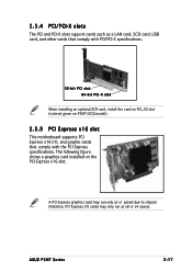
...run at x1 speed due to chipset limitation. PCI Express I /O, and graphic cards that comply with the PCI Express specifications. A PCI Express graphics card may only run only at x8 or x4 speed. ASUS P5MT Series 2-17 2.5.4 PCI/PCI-X slots The PCI and PCI-X slots support cards such as a LAN card, SCSI ...card, USB card, and other cards that comply with PCI/PCI-X specifications. 32-bit PCI slot 64-bit PCI-X slot When installing...
...run at x1 speed due to chipset limitation. PCI Express I /O, and graphic cards that comply with the PCI Express specifications. A PCI Express graphics card may only run only at x8 or x4 speed. ASUS P5MT Series 2-17 2.5.4 PCI/PCI-X slots The PCI and PCI-X slots support cards such as a LAN card, SCSI ...card, USB card, and other cards that comply with PCI/PCI-X specifications. 32-bit PCI slot 64-bit PCI-X slot When installing...

User Guide
Page 46
LAN2 USB34 P5MT Series USB 2.0 connector The USB port module is for USB 2.0 ports. Hard disk activity LED connector (4-pin HDLED1) This connector supplies power to 480 Mbps ... this connector, then install the module to a slot opening at the back of the system chassis. This USB connector complies with USB 2.0 specification that supports up . HDLED1 1 LAN2 P5MT Series SCSI/SATA card activity LED connector 5. Connect the USB module cable to this LED to light up to the hard disk activity...
LAN2 USB34 P5MT Series USB 2.0 connector The USB port module is for USB 2.0 ports. Hard disk activity LED connector (4-pin HDLED1) This connector supplies power to 480 Mbps ... this connector, then install the module to a slot opening at the back of the system chassis. This USB connector complies with USB 2.0 specification that supports up . HDLED1 1 LAN2 P5MT Series SCSI/SATA card activity LED connector 5. Connect the USB module cable to this LED to light up to the hard disk activity...

User Guide
Page 50
... the SMBus function. ® PSU_I2CCLK PSU_I2CDATA NC GND +3.3V Remote Sense LAN2 PSUSMB1 P5MT Series Power supply SMBus connector 1 3 . Find the proper orientation and push down firmly until the connectors completely fit. • Use of an SSI 12 V Specification 2.0-compliant power supply unit (PSU) that provides a minimum power of 450 W is for... GND GND GND 1 +3 Volts -12 Volts Ground PSON# Ground Ground Ground -5 Volts +5 Volts +5 Volts +5 Volts Ground +12V DC +12V DC +12V DC +12V DC 2-30 P5MT Series ATX power connectors Chapter 2: Hardware information
... the SMBus function. ® PSU_I2CCLK PSU_I2CDATA NC GND +3.3V Remote Sense LAN2 PSUSMB1 P5MT Series Power supply SMBus connector 1 3 . Find the proper orientation and push down firmly until the connectors completely fit. • Use of an SSI 12 V Specification 2.0-compliant power supply unit (PSU) that provides a minimum power of 450 W is for... GND GND GND 1 +3 Volts -12 Volts Ground PSON# Ground Ground Ground -5 Volts +5 Volts +5 Volts +5 Volts Ground +12V DC +12V DC +12V DC +12V DC 2-30 P5MT Series ATX power connectors Chapter 2: Hardware information

User Guide
Page 70
... window." 4.2.7 Pop-up window Select a menu item then press to display the other items (Advanced, Power, Boot, and Exit) on the menu bar displays the specific items for that menu. Press the Up/Down arrow keys or / keys to display a pop-up window Scroll bar 4.2.9 General help At the top right...
... window." 4.2.7 Pop-up window Select a menu item then press to display the other items (Advanced, Power, Boot, and Exit) on the menu bar displays the specific items for that menu. Press the Up/Down arrow keys or / keys to display a pop-up window Scroll bar 4.2.9 General help At the top right...

User Guide
Page 74
...] [SWDMA0] [SWDMA1] [SWDMA2] [MWDMA0] [MWDMA1] [MWDMA2] [UDMA0] [UDMA1] [UDMA2] SMART Monitoring [Auto] Sets the Smart Monitoring, Analysis, and Reporting Technology. Select [CDROM] if you are specifically configuring a CD-ROM drive. Configuration options: [Disabled] [Auto] Block (Multi-sector Transfer) [Auto] Enables or disables data multi-sectors transfers. Configuration options: [Auto] [Disabled] [Enabled...
...] [SWDMA0] [SWDMA1] [SWDMA2] [MWDMA0] [MWDMA1] [MWDMA2] [UDMA0] [UDMA1] [UDMA2] SMART Monitoring [Auto] Sets the Smart Monitoring, Analysis, and Reporting Technology. Select [CDROM] if you are specifically configuring a CD-ROM drive. Configuration options: [Disabled] [Auto] Block (Multi-sector Transfer) [Auto] Enables or disables data multi-sectors transfers. Configuration options: [Auto] [Disabled] [Enabled...

User Guide
Page 75
... Help F10 Save and Exit ESC Exit v02.58 (C)Copyright 1985-2004, American Megatrends, Inc. ASUS P5MT Series 4-17 4.3.6 System Information This menu gives you an overview of the general system specifications. Processor Displays the auto-detected CPU specification. AMI BIOS Displays the auto-detected BIOS information. System Memory Displays the auto-detected total...
... Help F10 Save and Exit ESC Exit v02.58 (C)Copyright 1985-2004, American Megatrends, Inc. ASUS P5MT Series 4-17 4.3.6 System Information This menu gives you an overview of the general system specifications. Processor Displays the auto-detected CPU specification. AMI BIOS Displays the auto-detected BIOS information. System Memory Displays the auto-detected total...

User Guide
Page 82
... Disabled 2 USB Ports 4 USB Ports Select Screen Select Item +- Configuration options: [Enabled] [Disabled] 4-24 Chapter 4: BIOS setup USB Function [4 USB Ports] Allows you to enable a specific number of the graphics controller to the DDR SDRAM. Configuration options: [PCI/PEG] [PEG/PCI] PEG Port Configuration PEG Port [Auto] Allows you to set...
... Disabled 2 USB Ports 4 USB Ports Select Screen Select Item +- Configuration options: [Enabled] [Disabled] 4-24 Chapter 4: BIOS setup USB Function [4 USB Ports] Allows you to enable a specific number of the graphics controller to the DDR SDRAM. Configuration options: [PCI/PEG] [PEG/PCI] PEG Port Configuration PEG Port [Auto] Allows you to set...

User Guide
Page 85
...the value in the system. When set to [No], BIOS configures all the devices int he system. Configuration options: [PCI Device] [Reserved] ASUS P5MT Series 4-27 Change Option F1 General Help F10 Save and Exit ESC Exit v02.58 (C)Copyright 1985-2004, American Megatrends, Inc. YES: Lets the... Configuration options: [Disabled] [Enabled] IRQXX assigned to [PCI Device] When set to [Yes], BIOS assigns an IRQ to [PCI Device], the specific IRQ is reserved for the PCI device latency timer register. Take caution when changing the settings of the PCI PnP menu items. Incorrect field values...
...the value in the system. When set to [No], BIOS configures all the devices int he system. Configuration options: [PCI Device] [Reserved] ASUS P5MT Series 4-27 Change Option F1 General Help F10 Save and Exit ESC Exit v02.58 (C)Copyright 1985-2004, American Megatrends, Inc. YES: Lets the... Configuration options: [Disabled] [Enabled] IRQXX assigned to [PCI Device] When set to [Yes], BIOS assigns an IRQ to [PCI Device], the specific IRQ is reserved for the PCI device latency timer register. Take caution when changing the settings of the PCI PnP menu items. Incorrect field values...

User Guide
Page 86
... 1985-2004, American Megatrends, Inc. 4.5 Power menu The Power menu items allow you to Enabled, the ACPI APIC table pointer is included in the Application-Specific Integrated Circuit (ASIC). Select an item then press to RSDT pointer list. Main Advanced Power ACPI APIC Support APM Configuration Hardware Monitor BIOS SETUP UTILITY...
... 1985-2004, American Megatrends, Inc. 4.5 Power menu The Power menu items allow you to Enabled, the ACPI APIC table pointer is included in the Application-Specific Integrated Circuit (ASIC). Select an item then press to RSDT pointer list. Main Advanced Power ACPI APIC Support APM Configuration Hardware Monitor BIOS SETUP UTILITY...

User Guide
Page 89
...49ºC/120ºF] [39ºC/102ºF] [5038RPM] [5045RPM] [N/A] [N/A] [N/A] [N/A] CPU1 Temperature. Use the down arrow key to display the detected temperatures. ASUS NCLV-D2 Series 4-31 Smart Fan Control CPU1 Temperature MB Temperature VCORE1 Voltage VCORE2 Voltage 3.3V Voltage 5V Voltage [Enabled] [60] [50] [ 1.236V] [... options: [Disabled] [Enabled] Power On By PS/2 Mouse [Disabled] When set to [Enabled], this parameter allows you to use specific keys on the keyboard to turn on the +5VSB lead. Change Option F1 General Help F10 Save and Exit ESC Exit v02.58 ...
...49ºC/120ºF] [39ºC/102ºF] [5038RPM] [5045RPM] [N/A] [N/A] [N/A] [N/A] CPU1 Temperature. Use the down arrow key to display the detected temperatures. ASUS NCLV-D2 Series 4-31 Smart Fan Control CPU1 Temperature MB Temperature VCORE1 Voltage VCORE2 Voltage 3.3V Voltage 5V Voltage [Enabled] [60] [50] [ 1.236V] [... options: [Disabled] [Enabled] Power On By PS/2 Mouse [Disabled] When set to [Enabled], this parameter allows you to use specific keys on the keyboard to turn on the +5VSB lead. Change Option F1 General Help F10 Save and Exit ESC Exit v02.58 ...

User Guide
Page 132
... open the A d a p t e r P r o p e r t i e s screen; Changing the adapter boot sequence To change the adapter boot sequence: 1. Property Adapter PCI Bus Dev/Func Boot Order Description Identifies the specific family of LSI Logic Host Adapters. When finished, press to modify this item. 3.
... open the A d a p t e r P r o p e r t i e s screen; Changing the adapter boot sequence To change the adapter boot sequence: 1. Property Adapter PCI Bus Dev/Func Boot Order Description Identifies the specific family of LSI Logic Host Adapters. When finished, press to modify this item. 3.
