
Motherboard Installation Guide
Page 14
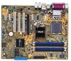
... 2. IDE_LED Reset PWRSW Intel® Pentium® 4 в 775 1 язычок A PnP B 14 ASUS P5GPL усский PS/2KBMS KBPWR T: Mouse B: Keyboard SPDIF_O ATX12V LGA775 Super I/O DDR DIMM_A1 (64 bit,184-pin...Top:Line In Center:Line Out Below:Mic In Marvell 88E8053 USBPW12 USBPW34 PWR_FAN PCIEX1_1 Intel R 915PL CPU_FAN PCIEX16 PCI1 CD P5GPL PCI2 ALC880 SPDIF_OUT PCI3 AAFP PCIEX1_2 CR2032 3V Lithium Cell CMOS Power Intel® ICH6 SATA2 SATA4 SATA1 SATA3 EATXPWR PRI_IDE...
... 2. IDE_LED Reset PWRSW Intel® Pentium® 4 в 775 1 язычок A PnP B 14 ASUS P5GPL усский PS/2KBMS KBPWR T: Mouse B: Keyboard SPDIF_O ATX12V LGA775 Super I/O DDR DIMM_A1 (64 bit,184-pin...Top:Line In Center:Line Out Below:Mic In Marvell 88E8053 USBPW12 USBPW34 PWR_FAN PCIEX1_1 Intel R 915PL CPU_FAN PCIEX16 PCI1 CD P5GPL PCI2 ALC880 SPDIF_OUT PCI3 AAFP PCIEX1_2 CR2032 3V Lithium Cell CMOS Power Intel® ICH6 SATA2 SATA4 SATA1 SATA3 EATXPWR PRI_IDE...

P5GPL English user's manual
Page 13
This chapter describes the motherboard features and the new technologies it supports. 1Product introduction ASUS P5GPL 1-1
This chapter describes the motherboard features and the new technologies it supports. 1Product introduction ASUS P5GPL 1-1

P5GPL English user's manual
Page 14
... the items in the long line of the above items is damaged or missing, contact your motherboard package for buying an ASUS® P5GPL motherboard! Before you for the following items. Motherboard ASUS P5GPL motherboard Cables 2 x Serial ATA signal cables 2 x Serial ATA power cables 1 x Ultra DMA/100 cables Floppy disk drive cable Accessories I/O shield...
... the items in the long line of the above items is damaged or missing, contact your motherboard package for buying an ASUS® P5GPL motherboard! Before you for the following items. Motherboard ASUS P5GPL motherboard Cables 2 x Serial ATA signal cables 2 x Serial ATA power cables 1 x Ultra DMA/100 cables Floppy disk drive cable Accessories I/O shield...

P5GPL English user's manual
Page 15
... up to 2GB of up to 150 MB/s data transfer rate. This high speed interface is fully compatible with Intel® 04B and 04A processors. ASUS P5GPL 1-3 The motherboard also supports the Intel ® Hyper-Threading Technology and is software compatible with 800 MHz Front Side Bus (FSB), 1 MB L2 cache, and...
... up to 2GB of up to 150 MB/s data transfer rate. This high speed interface is fully compatible with Intel® 04B and 04A processors. ASUS P5GPL 1-3 The motherboard also supports the Intel ® Hyper-Threading Technology and is software compatible with 800 MHz Front Side Bus (FSB), 1 MB L2 cache, and...
P5GPL English user's manual
Page 17
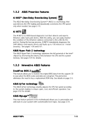
...shorts and faults up to buy a replacement ROM chip. ASUS P5GPL 1-5 See details on page 2-6. This protection eliminates the need to 100 meters at 1 meter accuracy. See page 2-19. See page 2-32 for details. 1.3.3 Innovative ASUS features CrashFree BIOS 2 This feature allows you to your ... The AI NET2 is a technology that detects and reports Ethernet cable faults and shorts. See pages 1-26 and 2-21. ASUS Hyper Path 2 technology The ASUS Hyper Path 2 technology optimizes the full potential of the Ethernet cable(s) connected to ensure quiet, cool, and efficient operation. ...
...shorts and faults up to buy a replacement ROM chip. ASUS P5GPL 1-5 See details on page 2-6. This protection eliminates the need to 100 meters at 1 meter accuracy. See page 2-19. See page 2-32 for details. 1.3.3 Innovative ASUS features CrashFree BIOS 2 This feature allows you to your ... The AI NET2 is a technology that detects and reports Ethernet cable faults and shorts. See pages 1-26 and 2-21. ASUS Hyper Path 2 technology The ASUS Hyper Path 2 technology optimizes the full potential of the Ethernet cable(s) connected to ensure quiet, cool, and efficient operation. ...

P5GPL English user's manual
Page 19
... rear part of the chassis as indicated in the correct orientation. Do not overtighten the screws! Place this side towards the rear of the chassis P5GPL ASUS P5GPL 1-7 Doing so can cause you place it . Make sure to unplug the power cord before installing or removing the motherboard. 1.5 Motherboard overview Before you install...
... rear part of the chassis as indicated in the correct orientation. Do not overtighten the screws! Place this side towards the rear of the chassis P5GPL ASUS P5GPL 1-7 Doing so can cause you place it . Make sure to unplug the power cord before installing or removing the motherboard. 1.5 Motherboard overview Before you install...

P5GPL English user's manual
Page 21
...4 LGA775 processor package should come with installation instructions for the CPU, fan and heatsink assembly. Contact your left. ASUS will process Return Merchandise Authorization (RMA) requests only if the motherboard comes with the cap on your retailer immediately ...the latter. • Upon purchase of the PnP cap. 1.6.1 Installling the CPU To install a CPU: 1. P5GPL P5GPL CPU Socket 775 Before installing the CPU, make sure that the socket box is facing towards you see any damage ...shipment/ transit-related. • Keep the cap after installing the motherboard. ASUS P5GPL 1-9
...4 LGA775 processor package should come with installation instructions for the CPU, fan and heatsink assembly. Contact your left. ASUS will process Return Merchandise Authorization (RMA) requests only if the motherboard comes with the cap on your retailer immediately ...the latter. • Upon purchase of the PnP cap. 1.6.1 Installling the CPU To install a CPU: 1. P5GPL P5GPL CPU Socket 775 Before installing the CPU, make sure that the socket box is facing towards you see any damage ...shipment/ transit-related. • Keep the cap after installing the motherboard. ASUS P5GPL 1-9

P5GPL English user's manual
Page 23
... Hyper-Threading Technology on the socket and damaging the CPU! Install an Intel® Pentium® 4 CPU that supports Hyper-Threading Technology. 2. Reboot the computer. ASUS P5GPL 1-11 B The CPU fits in the 775-land package with Hyper-Threading Technology. • Hyper-Threading Technology is recommended. • Make sure to Enabled. To...
... Hyper-Threading Technology on the socket and damaging the CPU! Install an Intel® Pentium® 4 CPU that supports Hyper-Threading Technology. 2. Reboot the computer. ASUS P5GPL 1-11 B The CPU fits in the 775-land package with Hyper-Threading Technology. • Hyper-Threading Technology is recommended. • Make sure to Enabled. To...

P5GPL English user's manual
Page 25
2. Push down two fasteners at a time in a diagonal sequence to plug this connector. A A A B B B A 3. Hardware monitoring errors can occur if you fail to secure the heatsink and fan B assembly in place, connect the CPU fan cable to connect the CPU fan connector! When the fan and heatsink assembly is in place. CPU_FAN GND P5GPL CPU FAN PWR CPU FAN IN CPU FAN PWM P5GPL CPU fan connector Do not forget to the connector on the motherboard labeled CPU_FAN. ASUS P5GPL 1-13
2. Push down two fasteners at a time in a diagonal sequence to plug this connector. A A A B B B A 3. Hardware monitoring errors can occur if you fail to secure the heatsink and fan B assembly in place, connect the CPU fan cable to connect the CPU fan connector! When the fan and heatsink assembly is in place. CPU_FAN GND P5GPL CPU FAN PWR CPU FAN IN CPU FAN PWM P5GPL CPU fan connector Do not forget to the connector on the motherboard labeled CPU_FAN. ASUS P5GPL 1-13

P5GPL English user's manual
Page 27
4. When reset, each fastener clockwise to reset the orientation. ASUS P5GPL 1-15 Rotate each fastener should be oriented as shown, with the narrow groove directed outward. Remove the heatsink and fan assembly from the motherboard. 5.
4. When reset, each fastener clockwise to reset the orientation. ASUS P5GPL 1-15 Rotate each fastener should be oriented as shown, with the narrow groove directed outward. Remove the heatsink and fan assembly from the motherboard. 5.

P5GPL English user's manual
Page 29
... ADD8608A8A-5B ADD8608A8A-5B KDL388P4LA-50 KDL388P4LA-50 NT5DS32M8CT-5T NT5DS32M8CT-5T K4H560838D-TCC4 K4H560838D-TCC4 K4H560838E-TCCC DD2508AMTA DD2508AMTA (Continued on the next page) ASUS P5GPL 1-17
... ADD8608A8A-5B ADD8608A8A-5B KDL388P4LA-50 KDL388P4LA-50 NT5DS32M8CT-5T NT5DS32M8CT-5T K4H560838D-TCC4 K4H560838D-TCC4 K4H560838E-TCCC DD2508AMTA DD2508AMTA (Continued on the next page) ASUS P5GPL 1-17

P5GPL English user's manual
Page 31
ASUS P5GPL 1-19 Simultaneously press the retaining clips outward to unlock the DIMM. 1 1 DDR DIMM notch Support the DIMM lightly with extra force. 2. DO NOT force a DIMM ...
ASUS P5GPL 1-19 Simultaneously press the retaining clips outward to unlock the DIMM. 1 1 DDR DIMM notch Support the DIMM lightly with extra force. 2. DO NOT force a DIMM ...
P5GPL English user's manual
Page 33
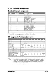
F - ASUS P5GPL 1-21 shared - - -- - shared - - -- -- - -- -- - When using PCI cards on shared slots, ensure that the drivers support "Share IRQ" or that the cards do not need IRQ ...
F - ASUS P5GPL 1-21 shared - - -- - shared - - -- -- - -- -- - When using PCI cards on shared slots, ensure that the drivers support "Share IRQ" or that the cards do not need IRQ ...

P5GPL English user's manual
Page 35
... the cap will cause system boot failure! Turn OFF the computer and unplug the power cord. 2. Plug the power cord and turn ON the computer. 6. ASUS P5GPL 1-23 The onboard button cell battery powers the RAM data in CMOS. Move the jumper cap from pins 1-2 (default) to overclocking, use the C.P.R. (CPU... system setup parameters by erasing the CMOS RTC RAM data. You can automatically reset parameter settings to re-enter data. CLRTC P5GPL 12 23 Normal (Default) Clear CMOS P5GPL Clear RTC RAM setting You do not need to clear the RTC when the system hangs due to clear the Real Time...
... the cap will cause system boot failure! Turn OFF the computer and unplug the power cord. 2. Plug the power cord and turn ON the computer. 6. ASUS P5GPL 1-23 The onboard button cell battery powers the RAM data in CMOS. Move the jumper cap from pins 1-2 (default) to overclocking, use the C.P.R. (CPU... system setup parameters by erasing the CMOS RTC RAM data. You can automatically reset parameter settings to re-enter data. CLRTC P5GPL 12 23 Normal (Default) Clear CMOS P5GPL Clear RTC RAM setting You do not need to clear the RTC when the system hangs due to clear the Real Time...

P5GPL English user's manual
Page 37
Keyboard power (3-pin KBPWR) This jumper allows you to wake up feature. This feature requires an ATX power supply that can supply at least 1A on the keyboard (the default is the Space Bar). KBPWR 12 23 +5V +5VSB (Default) P5GPL P5GPL Keyboard power setting ASUS P5GPL 1-25 3. Set this jumper to pins 2-3 (+5VSB) to enable or disable the keyboard wake-up the computer when you press a key on the +5VSB lead, and a corresponding setting in the BIOS.
Keyboard power (3-pin KBPWR) This jumper allows you to wake up feature. This feature requires an ATX power supply that can supply at least 1A on the keyboard (the default is the Space Bar). KBPWR 12 23 +5V +5VSB (Default) P5GPL P5GPL Keyboard power setting ASUS P5GPL 1-25 3. Set this jumper to pins 2-3 (+5VSB) to enable or disable the keyboard wake-up the computer when you press a key on the +5VSB lead, and a corresponding setting in the BIOS.

P5GPL English user's manual
Page 39
... are available for connecting USB 2.0 devices. 1 2 . This port connects an external audio output device via a coaxial S/PDIF cable. 1 4 . U S B 2 . 0 p o r t s 1 a n d 2 . S e r i a l c o n n e c t o r . C o a x i a l S / P D I F O u t p o r t . This port is for connecting USB 2.0 devices. 1 1 . P S / 2 k e y b o a r d p o r t ( p u r p l e ) . ASUS P5GPL 1-27 U S B 2 . 0 p o r t s 3 a n d 4 . Audio 2, 4, 6, or 8-channel configuration Port Light Blue Lime Pink Gray Black Yellow Orange Headset 2-channel Line In Line Out Mic In • • •...
... are available for connecting USB 2.0 devices. 1 2 . This port connects an external audio output device via a coaxial S/PDIF cable. 1 4 . U S B 2 . 0 p o r t s 1 a n d 2 . S e r i a l c o n n e c t o r . C o a x i a l S / P D I F O u t p o r t . This port is for connecting USB 2.0 devices. 1 1 . P S / 2 k e y b o a r d p o r t ( p u r p l e ) . ASUS P5GPL 1-27 U S B 2 . 0 p o r t s 3 a n d 4 . Audio 2, 4, 6, or 8-channel configuration Port Light Blue Lime Pink Gray Black Yellow Orange Headset 2-channel Line In Line Out Mic In • • •...

P5GPL English user's manual
Page 41
.../Slave connectors Connector SATA1, SATA2 SATA3, SATA4 Setting Master Slave Use Boot disk Data disk ASUS P5GPL 1-29 3. Serial ATA connectors (7-pin SATA1, SATA2, SATA3, SATA4) These connectors are for the Serial ATA signal cables for details. P5GPL P5GPL SATA connectors SATA2 GND RSATA_TXP2 RSATA_TXN2 GND RSATA_RXP2 RSATA_RXN2 GND SATA1 GND RSATA_TXP1 RSATA_TXN1 GND...
.../Slave connectors Connector SATA1, SATA2 SATA3, SATA4 Setting Master Slave Use Boot disk Data disk ASUS P5GPL 1-29 3. Serial ATA connectors (7-pin SATA1, SATA2, SATA3, SATA4) These connectors are for the Serial ATA signal cables for details. P5GPL P5GPL SATA connectors SATA2 GND RSATA_TXP2 RSATA_TXN2 GND RSATA_RXP2 RSATA_RXN2 GND SATA1 GND RSATA_TXP1 RSATA_TXN1 GND...

P5GPL English user's manual
Page 43
... PSON# Ground Ground Ground -5 Volts +5 Volts +5 Volts +5 Volts Ground +3 Volts +3 Volts Ground +5 Volts Ground +5 Volts Ground Power OK +5V Standby +12 Volts +12 Volts +3 Volts ASUS P5GPL 1-31 otherwise, the system will not boot up if the power is recommended when configuring a system with a minimum of a PSU with a higher power output is...
... PSON# Ground Ground Ground -5 Volts +5 Volts +5 Volts +5 Volts Ground +3 Volts +3 Volts Ground +5 Volts Ground +5 Volts Ground Power OK +5V Standby +12 Volts +12 Volts +3 Volts ASUS P5GPL 1-31 otherwise, the system will not boot up if the power is recommended when configuring a system with a minimum of a PSU with a higher power output is...

P5GPL English user's manual
Page 45
...Connect one end of the S/PDIF audio cable to this connector and the other end to the S/PDIF module. +5V SPDIFOUT GND P5GPL SPDIF_OUT P5GPL Digital audio connector The S/PDIF module is purchased separately. Front panel audio connector (10-1 pin AAFP) This connector is set to this...r item in the BIOS. 11. If you want to connect a high-definition front panel audio module to this connector to allow digital sound output. ASUS P5GPL 1-33 10. Digital Audio connector (4-1 pin SPDIF_OUT) This connector is for a chassis-mounted front panel audio I /O module cable to this connector is...
...Connect one end of the S/PDIF audio cable to this connector and the other end to the S/PDIF module. +5V SPDIFOUT GND P5GPL SPDIF_OUT P5GPL Digital audio connector The S/PDIF module is purchased separately. Front panel audio connector (10-1 pin AAFP) This connector is set to this...r item in the BIOS. 11. If you want to connect a high-definition front panel audio module to this connector to allow digital sound output. ASUS P5GPL 1-33 10. Digital Audio connector (4-1 pin SPDIF_OUT) This connector is for a chassis-mounted front panel audio I /O module cable to this connector is...

P5GPL English user's manual
Page 47
Detailed descriptions of the BIOS parameters are also provided. 2 BIOS setup ASUS P5GPL 2-1 This chapter tells how to change the system settings through the BIOS Setup menus.
Detailed descriptions of the BIOS parameters are also provided. 2 BIOS setup ASUS P5GPL 2-1 This chapter tells how to change the system settings through the BIOS Setup menus.


