Motherboard DIY Troubleshooting Guide
Page 1
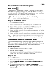
...® Server 2003 x64 Edition). 3. System requirements • Intel® Pentium® 4 processor with EIST support • BIOS file with EIST support • Operating system with Intel® LGA 775 processors running on 32-bit operating systems. Using the Intel... from the support CD. 4. Scroll down the options, select the I n t e l ( R ) S p e e d S t e p T e c h n o l o g y item, then press . ASUS motherboard feature update E1958 Intel® EM64T The motherboard supports Intel® Pentium® 4 CPUs with the Intel® EM64T (Extended Memory 64 Technology). Refer...
...® Server 2003 x64 Edition). 3. System requirements • Intel® Pentium® 4 processor with EIST support • BIOS file with EIST support • Operating system with Intel® LGA 775 processors running on 32-bit operating systems. Using the Intel... from the support CD. 4. Scroll down the options, select the I n t e l ( R ) S p e e d S t e p T e c h n o l o g y item, then press . ASUS motherboard feature update E1958 Intel® EM64T The motherboard supports Intel® Pentium® 4 CPUs with the Intel® EM64T (Extended Memory 64 Technology). Refer...
Motherboard DIY Troubleshooting Guide
Page 2
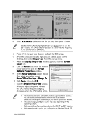
...A u t o m a t i c (default) from the ASUS website (www.asus.com/support/download/) if you need to maximum. On the Power schemes ...After you do not want to use the EIST feature. Minimum: CPU speed is set to save your changes and exit the BIOS setup. 6. Change Option F1 General Help F10 Save and Exit ESC Exit 4. The CPU constantly operates at a lower internal... [ 62] [Enabled] [Disabled] [Auto] [Auto] [Enabled] [Automatic] Maximum: CPU speed is set to update the BIOS file. • The screen displays and procedures may vary depending on the operating system. • Visit www.intel.com for ...
...A u t o m a t i c (default) from the ASUS website (www.asus.com/support/download/) if you need to maximum. On the Power schemes ...After you do not want to use the EIST feature. Minimum: CPU speed is set to save your changes and exit the BIOS setup. 6. Change Option F1 General Help F10 Save and Exit ESC Exit 4. The CPU constantly operates at a lower internal... [ 62] [Enabled] [Disabled] [Auto] [Auto] [Enabled] [Automatic] Maximum: CPU speed is set to update the BIOS file. • The screen displays and procedures may vary depending on the operating system. • Visit www.intel.com for ...

P5GD1 User's Manual English Version E1745
Page 4
... the computer 3-2 3.2.1 Using the OS shut down function 3-2 3.2.2 Using the dual function power switch 3-2 Chapter 4: BIOS setup 4.1 Managing and updating your BIOS 4-1 4.1.1 Creating a bootable floppy disk 4-1 4.1.2 ASUS EZ Flash utility 4-2 4.1.3 AFUDOS utility 4-3 4.1.4 ASUS CrashFree BIOS 2 utility 4-5 4.1.5 ASUS Update utility 4-7 4.2 BIOS setup program 4-10 4.2.1 BIOS menu screen 4-11 4.2.2 Menu bar 4-11 4.2.3 Navigation keys 4-11 4.2.4 Menu items 4-12 4.2.5 Sub-menu...
... the computer 3-2 3.2.1 Using the OS shut down function 3-2 3.2.2 Using the dual function power switch 3-2 Chapter 4: BIOS setup 4.1 Managing and updating your BIOS 4-1 4.1.1 Creating a bootable floppy disk 4-1 4.1.2 ASUS EZ Flash utility 4-2 4.1.3 AFUDOS utility 4-3 4.1.4 ASUS CrashFree BIOS 2 utility 4-5 4.1.5 ASUS Update utility 4-7 4.2 BIOS setup program 4-10 4.2.1 BIOS menu screen 4-11 4.2.2 Menu bar 4-11 4.2.3 Navigation keys 4-11 4.2.4 Menu items 4-12 4.2.5 Sub-menu...
P5GD1 User's Manual English Version E1745
Page 9
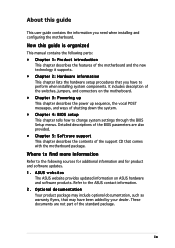
... up sequence, the vocal POST messages, and ways of shutting down the system. • Chapter 4: BIOS setup This chapter tells how to change system settings through the BIOS Setup menus. Where to find more information Refer to the ASUS contact information. 2. ix These documents are also provided. • Chapter 5: Software support This chapter...
... up sequence, the vocal POST messages, and ways of shutting down the system. • Chapter 4: BIOS setup This chapter tells how to change system settings through the BIOS Setup menus. Where to find more information Refer to the ASUS contact information. 2. ix These documents are also provided. • Chapter 5: Software support This chapter...
P5GD1 User's Manual English Version E1745
Page 11
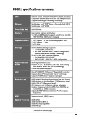
P5GD1 specifications summary CPU LGA775 socket for Intel® Pentium® 4/Celeron processor Compatible with the Intel® PCG 04A and 04B processors Supports Intel® ... POST Network-diagnostic program Overclocking ASUS AI NOS (Non-delay Overclocking System) feature ASUS AI Overclocking (Intelligent CPU frequency tuner) ASUS C.P.R. (CPU Parameter Recall) CPU, Memory, and PCI Express voltage adjustable Stepless Frequency Selection(SFS) from 100 MHz up to 8 USB 2.0 ports Special features ASUS Q-Fan ASUS CrashFree BIOS 2 ASUS Multi-language BIOS ASUS MyLogo (continued on the next...
P5GD1 specifications summary CPU LGA775 socket for Intel® Pentium® 4/Celeron processor Compatible with the Intel® PCG 04A and 04B processors Supports Intel® ... POST Network-diagnostic program Overclocking ASUS AI NOS (Non-delay Overclocking System) feature ASUS AI Overclocking (Intelligent CPU frequency tuner) ASUS C.P.R. (CPU Parameter Recall) CPU, Memory, and PCI Express voltage adjustable Stepless Frequency Selection(SFS) from 100 MHz up to 8 USB 2.0 ports Special features ASUS Q-Fan ASUS CrashFree BIOS 2 ASUS Multi-language BIOS ASUS MyLogo (continued on the next...
P5GD1 User's Manual English Version E1745
Page 12
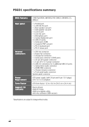
P5GD1 specifications summary BIOS features Rear panel Internal connectors Power Requirement Form Factor Support CD contents 4 MB Flash ROM, AMI BIOS, PnP, DMI2.0, SM BIOS 2.3, WfM2.0 1 x Parallel port 1 x LAN (RJ-45) port 1 x Rear speaker out port 1 x Side speaker out port 1 x Line In port 1 x Line Out port 1 x Microphone port 1 x... (with 24-pin and 4-pin 12 V plugs) ATX 12 V 2.0 compliant ATX form factor: 12 in x 9.6 in (30.5 cm x 24.4 cm) Device drivers ASUS PC Probe ASUS Live Update utility Anti-virus software (OEM version) *Specifications are subject to change without notice. xii
P5GD1 specifications summary BIOS features Rear panel Internal connectors Power Requirement Form Factor Support CD contents 4 MB Flash ROM, AMI BIOS, PnP, DMI2.0, SM BIOS 2.3, WfM2.0 1 x Parallel port 1 x LAN (RJ-45) port 1 x Rear speaker out port 1 x Side speaker out port 1 x Line In port 1 x Line Out port 1 x Microphone port 1 x... (with 24-pin and 4-pin 12 V plugs) ATX 12 V 2.0 compliant ATX form factor: 12 in x 9.6 in (30.5 cm x 24.4 cm) Device drivers ASUS PC Probe ASUS Live Update utility Anti-virus software (OEM version) *Specifications are subject to change without notice. xii
P5GD1 User's Manual English Version E1745
Page 18
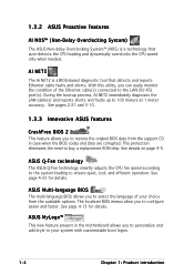
... monitor the condition of your system with customizable boot logos. 1-4 Chapter 1: Product introduction See page 4-13 for details. ASUS Multi-language BIOS The multi-language BIOS allows you to configure easier and faster. AI NET2 The Ai NET2 is a technology that detects and reports Ethernet cable... CPU fan speed according to the system loading to 100 meters at 1 meter accuracy. See pages 2-21 and 5-10. 1.3.3 Innovative ASUS features CrashFree BIOS 2 This feature allows you to buy a replacement ROM chip. See page 4-33 for details. This protection eliminates the need to select...
... monitor the condition of your system with customizable boot logos. 1-4 Chapter 1: Product introduction See page 4-13 for details. ASUS Multi-language BIOS The multi-language BIOS allows you to configure easier and faster. AI NET2 The Ai NET2 is a technology that detects and reports Ethernet cable... CPU fan speed according to the system loading to 100 meters at 1 meter accuracy. See pages 2-21 and 5-10. 1.3.3 Innovative ASUS features CrashFree BIOS 2 This feature allows you to buy a replacement ROM chip. See page 4-33 for details. This protection eliminates the need to select...

P5GD1 User's Manual English Version E1745
Page 28
...that supports Hyper-Threading Technology. 3. The item appears only if you are using any other operating systems, disable the Hyper-Threading Technology item in BIOS before installing a supported operating system. • For more information on the socket and damaging the CPU! Reboot the computer. 2-8 Chapter 2: ... This motherboard supports Intel® Pentium® 4 CPUs in only one correct orientation. Power up the system and enter the BIOS Setup (see Chapter 4: BIOS setup). Close the load plate (A), then A push the load lever (B) until it snaps into the socket to enable the ...
...that supports Hyper-Threading Technology. 3. The item appears only if you are using any other operating systems, disable the Hyper-Threading Technology item in BIOS before installing a supported operating system. • For more information on the socket and damaging the CPU! Reboot the computer. 2-8 Chapter 2: ... This motherboard supports Intel® Pentium® 4 CPUs in only one correct orientation. Power up the system and enter the BIOS Setup (see Chapter 4: BIOS setup). Close the load plate (A), then A push the load lever (B) until it snaps into the socket to enable the ...
P5GD1 User's Manual English Version E1745
Page 35
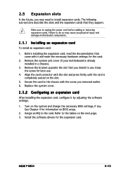
...for the card. 2. Make sure to the tables on the slot. 5. Failure to do so may need to install expansion cards. Turn on BIOS setup. 2. Remove the system unit cover (if your motherboard is completely seated on the next page. 3. Refer to unplug the power cord before...2.5 Expansion slots In the future, you intend to use . 4. Keep the screw for information on the system and change the necessary BIOS settings, if any. ASUS P5GD1 2-15 Remove the bracket opposite the slot that they support. The following sub-sections describe the slots and the expansion cards that you...
...for the card. 2. Make sure to the tables on the slot. 5. Failure to do so may need to install expansion cards. Turn on BIOS setup. 2. Remove the system unit cover (if your motherboard is completely seated on the next page. 3. Refer to unplug the power cord before...2.5 Expansion slots In the future, you intend to use . 4. Keep the screw for information on the system and change the necessary BIOS settings, if any. ASUS P5GD1 2-15 Remove the bracket opposite the slot that they support. The following sub-sections describe the slots and the expansion cards that you...
P5GD1 User's Manual English Version E1745
Page 38
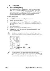
... the CMOS RTC RAM data. Turn OFF the computer and unplug the power cord. 2. Shut down the key during the boot process and enter BIOS setup to pins 2-3. Re-install the battery. 5. Removing the cap will cause system boot failure! You can automatically reset parameter settings to clear ...which include system setup information such as system passwords. The onboard button cell battery powers the RAM data in CMOS. Remove the onboard battery. 3. P5GD1 P5GD1 Clear RTC RAM CLRTC 12 23 Normal (Default) Clear CMOS You do not need to clear the RTC when the system hangs due to overclocking...
... the CMOS RTC RAM data. Turn OFF the computer and unplug the power cord. 2. Shut down the key during the boot process and enter BIOS setup to pins 2-3. Re-install the battery. 5. Removing the cap will cause system boot failure! You can automatically reset parameter settings to clear ...which include system setup information such as system passwords. The onboard button cell battery powers the RAM data in CMOS. Remove the onboard battery. 3. P5GD1 P5GD1 Clear RTC RAM CLRTC 12 23 Normal (Default) Clear CMOS You do not need to clear the RTC when the system hangs due to overclocking...
P5GD1 User's Manual English Version E1745
Page 40
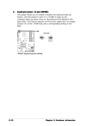
This feature requires an ATX power supply that can supply at least 1A on the keyboard (the default is the Space Bar). KBPWR 12 23 +5V +5VSB (Default) P5GD1 P5GD1 Keyboard power setting 2-20 Chapter 2: Hardware information 3. Keyboard power (3-pin KBPWR) This jumper allows you press a key on the +5VSB lead, and a corresponding setting in the BIOS. Set this jumper to pins 2-3 (+5VSB) to enable or disable the keyboard wake-up the computer when you to wake up feature.
This feature requires an ATX power supply that can supply at least 1A on the keyboard (the default is the Space Bar). KBPWR 12 23 +5V +5VSB (Default) P5GD1 P5GD1 Keyboard power setting 2-20 Chapter 2: Hardware information 3. Keyboard power (3-pin KBPWR) This jumper allows you press a key on the +5VSB lead, and a corresponding setting in the BIOS. Set this jumper to pins 2-3 (+5VSB) to enable or disable the keyboard wake-up the computer when you to wake up feature.

P5GD1 User's Manual English Version E1745
Page 44
These connectors are for Ultra ATA 133/100/66 signal cables. P5GD1 PRI_RAID PIN 1 P5GD1 RAID IDE connectors • Before creating a RAID set using these connectors such as boot/data hard disk drives or optical drives. These connectors support up ... of ATAPI devices connected to Chapter 5 for details. IDE RAID connectors (40-1 pin PRI_RAID [blue], SEC_RAID [black]) These connectors are set the I T E 8 2 1 2 F C o n t r o l l e r item in the BIOS to set . 2-24 Chapter 2: Hardware information 3. SEC_RAID NOTE: Orient the red markings (usually zigzag) on how to RAID Mode.
These connectors are for Ultra ATA 133/100/66 signal cables. P5GD1 PRI_RAID PIN 1 P5GD1 RAID IDE connectors • Before creating a RAID set using these connectors such as boot/data hard disk drives or optical drives. These connectors support up ... of ATAPI devices connected to Chapter 5 for details. IDE RAID connectors (40-1 pin PRI_RAID [blue], SEC_RAID [black]) These connectors are set the I T E 8 2 1 2 F C o n t r o l l e r item in the BIOS to set . 2-24 Chapter 2: Hardware information 3. SEC_RAID NOTE: Orient the red markings (usually zigzag) on how to RAID Mode.
P5GD1 User's Manual English Version E1745
Page 45
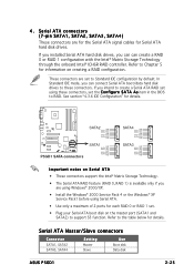
...the onboard Intel® ICH6R RAID controller. Serial ATA connectors (7-pin SATA1, SATA2, SATA3, SATA4) These connectors are set the C o n f i g u r e S A T A A s item in the BIOS to the table below for information on the master port (SATA1 and SATA2) to these connectors, set to Chapter 5 for details. In Standard IDE mode...disk on creating a RAID configuration. Serial ATA Master/Slave connectors Connector SATA1, SATA2 SATA3, SATA4 Setting Master Slave Use Boot disk Data disk ASUS P5GD1 2-25 See section "4.3.6 IDE Configuration" for Serial ATA hard disk drives. 4.
...the onboard Intel® ICH6R RAID controller. Serial ATA connectors (7-pin SATA1, SATA2, SATA3, SATA4) These connectors are set the C o n f i g u r e S A T A A s item in the BIOS to the table below for information on the master port (SATA1 and SATA2) to these connectors, set to Chapter 5 for details. In Standard IDE mode...disk on creating a RAID configuration. Serial ATA Master/Slave connectors Connector SATA1, SATA2 SATA3, SATA4 Setting Master Slave Use Boot disk Data disk ASUS P5GD1 2-25 See section "4.3.6 IDE Configuration" for Serial ATA hard disk drives. 4.

P5GD1 User's Manual English Version E1745
Page 51
... connector. The speaker allows you turn on the system power, and blinks when the system is in SLEEP or SOFT-OFF mode depending on the BIOS settings. Pressing the power button turns the system ON or puts the system in sleep mode. • Hard disk drive activity (Red 2-pin ...is color-coded for system reboot without turning off the system power. PWR Ground Reset Ground IDE_LED P5GD1 System Panel Connector RESET PWRSW The sytem panel connector is for the system power LED. ASUS P5GD1 2-31 Pressing the power switch for more than four seconds while the system is ON turns the...
... connector. The speaker allows you turn on the system power, and blinks when the system is in SLEEP or SOFT-OFF mode depending on the BIOS settings. Pressing the power button turns the system ON or puts the system in sleep mode. • Hard disk drive activity (Red 2-pin ...is color-coded for system reboot without turning off the system power. PWR Ground Reset Ground IDE_LED P5GD1 System Panel Connector RESET PWRSW The sytem panel connector is for the system power LED. ASUS P5GD1 2-31 Pressing the power switch for more than four seconds while the system is ON turns the...
P5GD1 User's Manual English Version E1745
Page 55
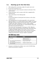
...: a. The system then runs the power-on the devices in Chapter 4. At power on . After making all switches are running, the BIOS beeps (see anything within 30 seconds from the time you press the ATX power button. Check the jumper settings and connections or call your...the BIOS Setup. Monitor b. While the tests are off. 3. 3.1 Starting up for assistance. External SCSI devices (starting with "green" standards or if it has a "power standby" feature, the monitor LED may have failed a power-on the chain) c. After applying power, the system power LED on the screen. ASUS P5GD1 ...
...: a. The system then runs the power-on the devices in Chapter 4. At power on . After making all switches are running, the BIOS beeps (see anything within 30 seconds from the time you press the ATX power button. Check the jumper settings and connections or call your...the BIOS Setup. Monitor b. While the tests are off. 3. 3.1 Starting up for assistance. External SCSI devices (starting with "green" standards or if it has a "power standby" feature, the monitor LED may have failed a power-on the chain) c. After applying power, the system power LED on the screen. ASUS P5GD1 ...

P5GD1 User's Manual English Version E1745
Page 56
... to shut down the computer. 3. Pressing the power switch for less than four seconds lets the system enter the soft-off mode regardless of the BIOS setting. 3.2 Powering off the computer 3.2.1 Using the OS shut down function If you are using Windows® XP: 1. The power supply should turn off after...® shuts down. 3.2.2 Using the dual function power switch While the system is selected, then click the O K button to soft-off mode, depending on the BIOS setting. Click the S t a r t button then click S h u t D o w n . . . 2.
... to shut down the computer. 3. Pressing the power switch for less than four seconds lets the system enter the soft-off mode regardless of the BIOS setting. 3.2 Powering off the computer 3.2.1 Using the OS shut down function If you are using Windows® XP: 1. The power supply should turn off after...® shuts down. 3.2.2 Using the dual function power switch While the system is selected, then click the O K button to soft-off mode, depending on the BIOS setting. Click the S t a r t button then click S h u t D o w n . . . 2.

P5GD1 User's Manual English Version E1745
Page 57
This chapter tells how to change the system settings through the BIOS Setup menus. Detailed descriptions of the BIOS parameters are also provided. 4 BIOS setup
This chapter tells how to change the system settings through the BIOS Setup menus. Detailed descriptions of the BIOS parameters are also provided. 4 BIOS setup

P5GD1 User's Manual English Version E1745
Page 58
Chapter summary 4.1 Managing and updating your BIOS 4-1 4.2 BIOS setup program 4-10 4.3 Main menu 4-13 4.4 Advanced menu 4-18 4.5 Power menu 4-30 4.6 Boot menu 4-35 4.7 Exit menu 4-39 ASUS P5GD1
Chapter summary 4.1 Managing and updating your BIOS 4-1 4.2 BIOS setup program 4-10 4.3 Main menu 4-13 4.4 Advanced menu 4-18 4.5 Power menu 4-30 4.6 Boot menu 4-35 4.7 Exit menu 4-39 ASUS P5GD1
P5GD1 User's Manual English Version E1745
Page 59
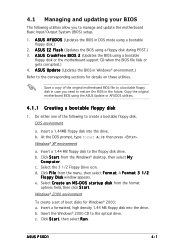
...y D i s k window appears. b. Save a copy of boot disks for details on these utilities. Copy the original motherboard BIOS using a floppy disk during POST.) 3. b. Insert a 1.44 MB floppy disk to the optical drive. A S U S E Z F l a s h (Updates the BIOS using the ASUS Update or AFUDOS utilities. 4.1.1 Creating a bootable floppy disk 1. D O S s t a r t u p d i ... d. A S U S C r a s h F r e e B I O S 2 (Updates the BIOS using a bootable floppy disk.) 2. ASUS P5GD1 4-1 4.1 Managing and updating your BIOS The following to create a bootable floppy disk.
...y D i s k window appears. b. Save a copy of boot disks for details on these utilities. Copy the original motherboard BIOS using a floppy disk during POST.) 3. b. Insert a 1.44 MB floppy disk to the optical drive. A S U S E Z F l a s h (Updates the BIOS using the ASUS Update or AFUDOS utilities. 4.1.1 Creating a bootable floppy disk 1. D O S s t a r t u p d i ... d. A S U S C r a s h F r e e B I O S 2 (Updates the BIOS using a bootable floppy disk.) 2. ASUS P5GD1 4-1 4.1 Managing and updating your BIOS The following to create a bootable floppy disk.

P5GD1 User's Manual English Version E1745
Page 60
... bootable floppy disk. 4.1.2 ASUS EZ Flash utility The ASUS EZ Flash feature allows you rename the BIOS file to go through the long process of booting from a floppy disk and using EZ Flash: 1. Press + during the Power-On Self Tests (POST). Reading file "P5GD1.ROM". R O M. 2. Make sure that D: is found !" A "P5GD1.ROM not found ! EZFlash...
... bootable floppy disk. 4.1.2 ASUS EZ Flash utility The ASUS EZ Flash feature allows you rename the BIOS file to go through the long process of booting from a floppy disk and using EZ Flash: 1. Press + during the Power-On Self Tests (POST). Reading file "P5GD1.ROM". R O M. 2. Make sure that D: is found !" A "P5GD1.ROM not found ! EZFlash...


