User Manual
Page 3
Contents Notices...vi Safety information vii About this guide viii P5G41T-M LX specifications summary ix Chapter 1: Product introduction 1.1 Welcome 1-1 1.2 Package contents 1-1 1.3 Special features 1-1 1.3.1 Product highlights 1-1 1.3.2 Innovative ASUS features 1-2 1.4 Before you proceed 1-4 1.5 Motherboard overview 1-5 1.5.1 Placement direction 1-5 1.5.2 Screw holes 1-5 1.5.3 Motherboard layout 1-6 1.5.4 Layout contents 1-6 1.6 Central Processing Unit (CPU 1-7 1.6.1 Installing the CPU 1-7 1.6.2 Installing the CPU heatsink and fan 1-10...
Contents Notices...vi Safety information vii About this guide viii P5G41T-M LX specifications summary ix Chapter 1: Product introduction 1.1 Welcome 1-1 1.2 Package contents 1-1 1.3 Special features 1-1 1.3.1 Product highlights 1-1 1.3.2 Innovative ASUS features 1-2 1.4 Before you proceed 1-4 1.5 Motherboard overview 1-5 1.5.1 Placement direction 1-5 1.5.2 Screw holes 1-5 1.5.3 Motherboard layout 1-6 1.5.4 Layout contents 1-6 1.6 Central Processing Unit (CPU 1-7 1.6.1 Installing the CPU 1-7 1.6.2 Installing the CPU heatsink and fan 1-10...

User Manual
Page 15
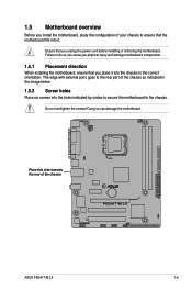
... motherboard components. 1.5.1 Placement direction When installing the motherboard, ensure that you unplug the power cord before installing or removing the motherboard. Ensure that you place it . Do not overtighten the screws! 1.5 Motherboard overview Before you install the motherboard, study the configuration of your chassis to the rear part of the chassis ASUS P5G41T-M LX 1-5
... motherboard components. 1.5.1 Placement direction When installing the motherboard, ensure that you unplug the power cord before installing or removing the motherboard. Ensure that you place it . Do not overtighten the screws! 1.5 Motherboard overview Before you install the motherboard, study the configuration of your chassis to the rear part of the chassis ASUS P5G41T-M LX 1-5
User Manual
Page 18
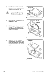
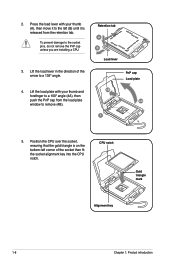
... with your thumb and forefinger to a 100º angle (4A), then push the PnP cap from the retention tab. Lift the load lever in the direction of the socket then fit the socket alignment key into the CPU notch. To prevent damage to a 135º angle. 4. Press the load lever with...
... with your thumb and forefinger to a 100º angle (4A), then push the PnP cap from the retention tab. Lift the load lever in the direction of the socket then fit the socket alignment key into the CPU notch. To prevent damage to a 135º angle. 4. Press the load lever with...
User Manual
Page 19
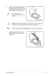
If it gets into your eyes or touches your finger directly. 7. 6. Apply some Thermal Interface Material to the exposed area of the CPU that you wash it snaps into the A retention tab. Close the load plate (A), ... spread the paste with , ensuring that it is spread in contact with your skin, ensure that the heatsink will be in an even thin layer. B ASUS P5G41T-M LX 1-9 DO NOT eat the Thermal Interface Material. If so, skip this step. Some heatsinks come with pre-applied thermal paste.
If it gets into your eyes or touches your finger directly. 7. 6. Apply some Thermal Interface Material to the exposed area of the CPU that you wash it snaps into the A retention tab. Close the load plate (A), ... spread the paste with , ensuring that it is spread in contact with your skin, ensure that the heatsink will be in an even thin layer. B ASUS P5G41T-M LX 1-9 DO NOT eat the Thermal Interface Material. If so, skip this step. Some heatsinks come with pre-applied thermal paste.
User Manual
Page 20
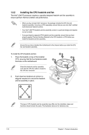
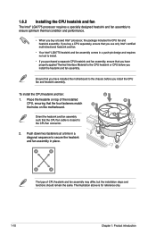
... fasteners at a time in a diagonal sequence to the chassis before you buy a CPU separately, ensure that you use only Intel®‑certified multi‑directional heatsink and fan. • Your Intel® LGA775 heatsink and fan assembly comes in place. A B A B B A 1 1 B A The type of the installed CPU, ensuring that the CPU...
... fasteners at a time in a diagonal sequence to the chassis before you buy a CPU separately, ensure that you use only Intel®‑certified multi‑directional heatsink and fan. • Your Intel® LGA775 heatsink and fan assembly comes in place. A B A B B A 1 1 B A The type of the installed CPU, ensuring that the CPU...

User Manual
Page 26
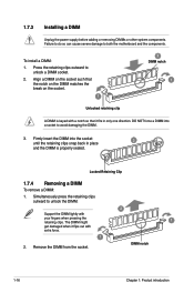
... from the socket. DIMM notch 1-16 Chapter 1: Product introduction DO NOT force a DIMM into the socket until the retaining clips snap back in only one direction. Locked Retaining Clip 1.7.4 Removing a DIMM To remove a DIMM: 1. Align a DIMM on the socket such that the notch on the DIMM matches the break on the...
... from the socket. DIMM notch 1-16 Chapter 1: Product introduction DO NOT force a DIMM into the socket until the retaining clips snap back in only one direction. Locked Retaining Clip 1.7.4 Removing a DIMM To remove a DIMM: 1. Align a DIMM on the socket such that the notch on the DIMM matches the break on the...
User Manual
Page 49
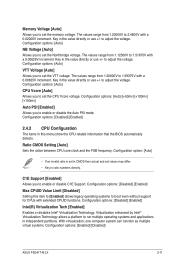
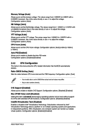
... ration between CPU core clock and the FSB frequency. C1E Support [Enabled] Allows you to set the VTT voltage. Key in the value directly or use +/- The values range from 1.20000V to adjust the voltage. to 1.59375V with extended CPUID functions. Configuration options: [Disabled] ... [Enabled] [Disabled] ASUS P5G41T-M LX 2-11 Configuration options: [Auto] NB Voltage [Auto] Allows you to adjust the voltage. Configuration option: [Auto] • If an invalid ratio is set in CMOS then actual and set values may differ. • Key in the value directly or use +/- The ...
... ration between CPU core clock and the FSB frequency. C1E Support [Enabled] Allows you to set the VTT voltage. Key in the value directly or use +/- The values range from 1.20000V to adjust the voltage. to 1.59375V with extended CPUID functions. Configuration options: [Disabled] ... [Enabled] [Disabled] ASUS P5G41T-M LX 2-11 Configuration options: [Auto] NB Voltage [Auto] Allows you to adjust the voltage. Configuration option: [Auto] • If an invalid ratio is set in CMOS then actual and set values may differ. • Key in the value directly or use +/- The ...

User Manual
Page 51
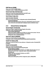
...select the front panel support type. If High Definition Audio Front Panel used, set to [EPP]. Configuration options: [Normal] [Bi-Directional] [EPP] [ECP] ECP Mode DMA Channel [DMA3] Appears only when the Parallel Port Mode is set to select the Serial ...IRQ [IRQ7] Allows you to [ECP]. This item appears only when the Onboard LAN item is set to Enabled. Configuration options: [IRQ5] [IRQ7] ASUS P5G41T-M LX 2-13 Configuration options: [Disabled] [Enabled] Serial Port1 Address [3F8/IRQ4] Allows you to set the Parallel Port ECP DMA. Configuration options: [Disabled...
...select the front panel support type. If High Definition Audio Front Panel used, set to [EPP]. Configuration options: [Normal] [Bi-Directional] [EPP] [ECP] ECP Mode DMA Channel [DMA3] Appears only when the Parallel Port Mode is set to select the Serial ...IRQ [IRQ7] Allows you to [ECP]. This item appears only when the Onboard LAN item is set to Enabled. Configuration options: [IRQ5] [IRQ7] ASUS P5G41T-M LX 2-13 Configuration options: [Disabled] [Enabled] Serial Port1 Address [3F8/IRQ4] Allows you to set the Parallel Port ECP DMA. Configuration options: [Disabled...

User Manual
Page 62
... (EC conformity marking) Position : CEO Name : Jerry Shen Signature TAIWAN ASUS COMPUTER GmbH HARKORT STR. 21-23, 40880 RATINGEN GERMANY declare the following apparatus: Product name : Model name : Motherboard P5G41T-M LX conform with part 15 of the following directives: 2004/108/EC-EMC Directive EN 55022:2006+A1:2007 EN 61000-3-2:2006 EN 55013:2001...
... (EC conformity marking) Position : CEO Name : Jerry Shen Signature TAIWAN ASUS COMPUTER GmbH HARKORT STR. 21-23, 40880 RATINGEN GERMANY declare the following apparatus: Product name : Model name : Motherboard P5G41T-M LX conform with part 15 of the following directives: 2004/108/EC-EMC Directive EN 55022:2006+A1:2007 EN 61000-3-2:2006 EN 55013:2001...

User Manual
Page 3
Contents Notices...vi Safety information vii About this guide vii P5G41T-M LX specifications summary ix Chapter 1: Product introduction 1.1 Welcome 1-1 1.2 Package contents 1-1 1.3 Special features 1-1 1.3.1 Product highlights 1-1 1.3.2 Innovative ASUS features 1-2 1.4 Before you proceed 1-4 1.5 Motherboard overview 1-5 1.5.1 Placement direction 1-5 1.5.2 Screw holes 1-5 1.5.3 Motherboard layout 1-6 1.5.4 Layout contents 1-6 1.6 Central Processing Unit (CPU 1-7 1.6.1 Installing the CPU 1-7 1.6.2 Installing the CPU heatsink and fan 1-10...
Contents Notices...vi Safety information vii About this guide vii P5G41T-M LX specifications summary ix Chapter 1: Product introduction 1.1 Welcome 1-1 1.2 Package contents 1-1 1.3 Special features 1-1 1.3.1 Product highlights 1-1 1.3.2 Innovative ASUS features 1-2 1.4 Before you proceed 1-4 1.5 Motherboard overview 1-5 1.5.1 Placement direction 1-5 1.5.2 Screw holes 1-5 1.5.3 Motherboard layout 1-6 1.5.4 Layout contents 1-6 1.6 Central Processing Unit (CPU 1-7 1.6.1 Installing the CPU 1-7 1.6.2 Installing the CPU heatsink and fan 1-10...
User Manual
Page 15
Do not overtighten the screws! Doing so can cause you physical injury and damage motherboard components. 1.5.1 Placement direction When installing the motherboard, ensure that you place it . Ensure that you unplug the power cord before installing or removing the motherboard. Place this side ... the holes indicated by circles to secure the motherboard to the chassis. The edge with external ports goes to the rear part of the chassis ASUS P5G41T-M LX 1-5
Do not overtighten the screws! Doing so can cause you physical injury and damage motherboard components. 1.5.1 Placement direction When installing the motherboard, ensure that you place it . Ensure that you unplug the power cord before installing or removing the motherboard. Place this side ... the holes indicated by circles to secure the motherboard to the chassis. The edge with external ports goes to the rear part of the chassis ASUS P5G41T-M LX 1-5
User Manual
Page 18
... remove the PnP cap unless you are installing a CPU. 3. Retention tab A B Load lever PnP cap Load plate 4B 4A 3 5. Lift the load lever in the direction of the socket then fit the socket alignment key into the CPU notch.
... remove the PnP cap unless you are installing a CPU. 3. Retention tab A B Load lever PnP cap Load plate 4B 4A 3 5. Lift the load lever in the direction of the socket then fit the socket alignment key into the CPU notch.

User Manual
Page 19
... paste with your skin, ensure that it snaps into your eyes or touches your finger directly. 7. 6. If so, skip this step. DO NOT eat the Thermal Interface Material. If it off immediately, and seek professional medical help. B ASUS P5G41T-M LX 1-9 Some heatsinks come with , ensuring that you wash it gets into the A retention tab...
... paste with your skin, ensure that it snaps into your eyes or touches your finger directly. 7. 6. If so, skip this step. DO NOT eat the Thermal Interface Material. If it off immediately, and seek professional medical help. B ASUS P5G41T-M LX 1-9 Some heatsinks come with , ensuring that you wash it gets into the A retention tab...
User Manual
Page 20
... fasteners at a time in a diagonal sequence to install. • If you buy a CPU separately, ensure that you use only Intel®‑certified multi‑directional heatsink and fan. • Your Intel® LGA775 heatsink and fan assembly comes in a push-pin design and requires no tool to secure the heatsink...
... fasteners at a time in a diagonal sequence to install. • If you buy a CPU separately, ensure that you use only Intel®‑certified multi‑directional heatsink and fan. • Your Intel® LGA775 heatsink and fan assembly comes in a push-pin design and requires no tool to secure the heatsink...
User Manual
Page 26
.... 1 2 DIMM notch 1 Unlocked retaining clip A DIMM is properly seated. DO NOT force a DIMM into the socket until the retaining clips snap back in only one direction. To install a DIMM: 1. The DIMM might 1 get damaged when it fits in place 3 and the DIMM is keyed with a notch so that it flips out...
.... 1 2 DIMM notch 1 Unlocked retaining clip A DIMM is properly seated. DO NOT force a DIMM into the socket until the retaining clips snap back in only one direction. To install a DIMM: 1. The DIMM might 1 get damaged when it fits in place 3 and the DIMM is keyed with a notch so that it flips out...
User Manual
Page 49
...support for CPUs with a 0.02000V increment. Configuration options: [Disabled] [Enabled] 2.4.2 CPU Configuration The items in the value directly or use +/- Configuration options: [Disabled] [Enabled] Intel(R) Virtualization Tech [Enabled] Enables or disables Intel® Virtualization Technology...Enabled] [Disabled] ASUS P5G41T-M LX 2-11 The values range from 1.12500V to set values may differ. • Key in the value directly or use +/- to run multiple operating systems and applications in the value directly or use +/- Key in ratio numbers directly. Configuration options: ...
...support for CPUs with a 0.02000V increment. Configuration options: [Disabled] [Enabled] 2.4.2 CPU Configuration The items in the value directly or use +/- Configuration options: [Disabled] [Enabled] Intel(R) Virtualization Tech [Enabled] Enables or disables Intel® Virtualization Technology...Enabled] [Disabled] ASUS P5G41T-M LX 2-11 The values range from 1.12500V to set values may differ. • Key in the value directly or use +/- to run multiple operating systems and applications in the value directly or use +/- Key in ratio numbers directly. Configuration options: ...
User Manual
Page 51
... set to [ECP]. Configuration options: [Normal] [Bi-Directional] [EPP] [ECP] ECP Mode DMA Channel [DMA3] Appears only when the Parallel Port Mode is set this item to [HD Audio] mode. This item allows you to select the Parallel Port mode. Configuration options: [IRQ5] [IRQ7] ASUS P5G41T-M LX 2-13 Configuration options: [Disabled] [378] [278] [3BC...
... set to [ECP]. Configuration options: [Normal] [Bi-Directional] [EPP] [ECP] ECP Mode DMA Channel [DMA3] Appears only when the Parallel Port Mode is set this item to [HD Audio] mode. This item allows you to select the Parallel Port mode. Configuration options: [IRQ5] [IRQ7] ASUS P5G41T-M LX 2-13 Configuration options: [Disabled] [378] [278] [3BC...