
User Manual
Page 1
P5G41-M SI Motherboard
P5G41-M SI Motherboard
User Manual
Page 3
Contents Notices...v Safety information vi Safety information vii P5G41-M SI specifications summary viii Chapter 1: Product introduction 1.1 Before you proceed 1-1 1.2 Motherboard overview 1-2 1.2.1 Motherboard layout 1-2 1.2.2 Layout contents 1-2 1.3 Central Processing Unit (CPU 1-3 1.4...1.8.1 Installing an operating system 1-17 1.8.2 Support DVD information 1-17 Chapter 2: BIOS information 2.1 Managing and updating your BIOS 2-1 2.1.1 ASUS Update utility 2-1 2.1.2 ASUS EZ Flash 2 utility 2-2 2.1.3 ASUS CrashFree BIOS 2-3 2.2 BIOS setup program 2-4 2.2.1 BIOS menu screen 2-5 iii
Contents Notices...v Safety information vi Safety information vii P5G41-M SI specifications summary viii Chapter 1: Product introduction 1.1 Before you proceed 1-1 1.2 Motherboard overview 1-2 1.2.1 Motherboard layout 1-2 1.2.2 Layout contents 1-2 1.3 Central Processing Unit (CPU 1-3 1.4...1.8.1 Installing an operating system 1-17 1.8.2 Support DVD information 1-17 Chapter 2: BIOS information 2.1 Managing and updating your BIOS 2-1 2.1.1 ASUS Update utility 2-1 2.1.2 ASUS EZ Flash 2 utility 2-2 2.1.3 ASUS CrashFree BIOS 2-3 2.2 BIOS setup program 2-4 2.2.1 BIOS menu screen 2-5 iii
User Manual
Page 8
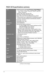
... CPU, otherwise the system will show a warning message and automatically shutdown. resolution: 2048 x 1536 x 32Bpp @75Hz DVI Max. P5G41-M SI specifications summary CPU Chipset System bus Memory Expansion slots VGA Storage LAN Audio USB ASUS Special features LGA775 Socket for Intel® C��o�re�™�2��E��...
... CPU, otherwise the system will show a warning message and automatically shutdown. resolution: 2048 x 1536 x 32Bpp @75Hz DVI Max. P5G41-M SI specifications summary CPU Chipset System bus Memory Expansion slots VGA Storage LAN Audio USB ASUS Special features LGA775 Socket for Intel® C��o�re�™�2��E��...
User Manual
Page 9
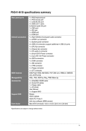
ix P5G41-M SI specifications summary Rear panel ports Internal connectors BIOS features Manageability Accessories Support DVD Form factor 1 x PS/2 keyboard port 1 x PS/2 mouse port 1 x LAN (RJ-45) port 4 x ... v2.0a WOL, PXE, WOR by Ring, PME Wake Up 1 x UltraDMA 100/66 cable 2 x Serial ATA cables 1 x Floppy cable 1 x I/O shield User Manual 1 x Support DVD Drivers ASUS Update ASUS PC Probe II Anti-virus software (OEM version) MicroATX form factor: 9.6 in x 9.6 in (24.4 cm x 24.4cm) *Specifications are subject to change without notice.
ix P5G41-M SI specifications summary Rear panel ports Internal connectors BIOS features Manageability Accessories Support DVD Form factor 1 x PS/2 keyboard port 1 x PS/2 mouse port 1 x LAN (RJ-45) port 4 x ... v2.0a WOL, PXE, WOR by Ring, PME Wake Up 1 x UltraDMA 100/66 cable 2 x Serial ATA cables 1 x Floppy cable 1 x I/O shield User Manual 1 x Support DVD Drivers ASUS Update ASUS PC Probe II Anti-virus software (OEM version) MicroATX form factor: 9.6 in x 9.6 in (24.4 cm x 24.4cm) *Specifications are subject to change without notice.
User Manual
Page 10
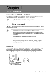
... note of the items is damaged or missing, contact your motherboard package. Before you for the list of the onboard LED. SB_PWR P5G41-M SI ON OFF Standby Power Powered Off P5G41-M SI Onboard LED 1-1 Chapter 1: Product introduction Refer to indicate that the system is a reminder that lights up to page ix for buying an...
... note of the items is damaged or missing, contact your motherboard package. Before you for the list of the onboard LED. SB_PWR P5G41-M SI ON OFF Standby Power Powered Off P5G41-M SI Onboard LED 1-1 Chapter 1: Product introduction Refer to indicate that the system is a reminder that lights up to page ix for buying an...

User Manual
Page 11
...) 1-13 13. CHA_FAN LGA775 USB34 USBPW1-4 LAN1_USB12 RTL 8112L COM1 AUDIO ICS 9LRS954 PCIEX16 Intel® G41 Super I/O PCI1 P5G41-M SI PCI2 VIA VT1708S CD AAFP SPDIF_OUT PCI3 FLOPPY LPT Lithium Cell CMOS Power Intel® ICH7 SATA4 SATA3 SATA2 SATA1 USB56 USBPW5-8...fan connectors (4-pin CPU_FAN, 3-pin CHA_FAN) 5. Serial ATA connectors (7-pin SATA1-4) 1-11 19. System panel connector (10-1 pin F_PANEL) 1-14 ASUS P5G41-M SI 1-2 The edge with external ports goes to the chassis. Keyboard power (3-pin KBPWR) 2. Front panel audio connector (10-1 pin AAFP) 1-15...
...) 1-13 13. CHA_FAN LGA775 USB34 USBPW1-4 LAN1_USB12 RTL 8112L COM1 AUDIO ICS 9LRS954 PCIEX16 Intel® G41 Super I/O PCI1 P5G41-M SI PCI2 VIA VT1708S CD AAFP SPDIF_OUT PCI3 FLOPPY LPT Lithium Cell CMOS Power Intel® ICH7 SATA4 SATA3 SATA2 SATA1 USB56 USBPW5-8...fan connectors (4-pin CPU_FAN, 3-pin CHA_FAN) 5. Serial ATA connectors (7-pin SATA1-4) 1-11 19. System panel connector (10-1 pin F_PANEL) 1-14 ASUS P5G41-M SI 1-2 The edge with external ports goes to the chassis. Keyboard power (3-pin KBPWR) 2. Front panel audio connector (10-1 pin AAFP) 1-15...
User Manual
Page 12
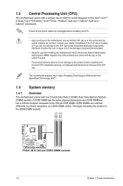
... resulting from incorrect CPU installation/removal, or misplacement/loss/incorrect removal of the DDR2 DIMM sockets: DIMM_A1 DIMM_A2 DIMM_B1 DIMM_B2 P5G41-M SI P5G41-M SI 240-pin DDR2 DIMM sockets 1-3 Chapter 1: Product introduction Ensure that all power cables are unplugged before installing the CPU....Quad / Core™2 Exreme / Core™2 Duo / Pentium® dual-core / Celeron® dual-core / Celeron® processors. ASUS will process Return Merchandise Authorization (RMA) requests only if the motherboard comes with four Double Data Rate 2 (DDR2) Dual Inline Memory Module (DIMM...
... resulting from incorrect CPU installation/removal, or misplacement/loss/incorrect removal of the DDR2 DIMM sockets: DIMM_A1 DIMM_A2 DIMM_B1 DIMM_B2 P5G41-M SI P5G41-M SI 240-pin DDR2 DIMM sockets 1-3 Chapter 1: Product introduction Ensure that all power cables are unplugged before installing the CPU....Quad / Core™2 Exreme / Core™2 Duo / Pentium® dual-core / Celeron® dual-core / Celeron® processors. ASUS will process Return Merchandise Authorization (RMA) requests only if the motherboard comes with four Double Data Rate 2 (DDR2) Dual Inline Memory Module (DIMM...

User Manual
Page 13
.... • For dual-channel configuration, you are using a 32-bit Windows® OS. - or - Under the default state, some memory modules for the OS can : - ASUS P5G41-M SI 1-4
.... • For dual-channel configuration, you are using a 32-bit Windows® OS. - or - Under the default state, some memory modules for the OS can : - ASUS P5G41-M SI 1-4

User Manual
Page 14
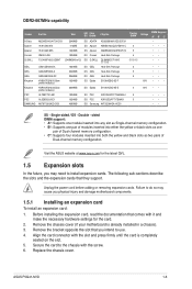
...;• •• ••• • • •• •• •• •• 5 ••• 5 ••• 1-5 Chapter 1: Product introduction P5G41-M SI Motherboard Qualified Vendors List (QVL) DDR2-800MHz capability Vendor Part No. Size SS/ Chip DS Brand Chip No.
...;• •• ••• • • •• •• •• •• 5 ••• 5 ••• 1-5 Chapter 1: Product introduction P5G41-M SI Motherboard Qualified Vendors List (QVL) DDR2-800MHz capability Vendor Part No. Size SS/ Chip DS Brand Chip No.
User Manual
Page 15
Visit the ASUS website at www.asus.com for the card. 2. DS ADATA SS Apacer SS Apacer DS Corsair DS G.SKILL DS GEIL DS GEIL DS GEIL SS Elpida AD20908A8A-3EG 30724 ... 2048MB 1024MB 2048MB 1024MB 1024MB 4096MB SS/ Chip DS Brand Chip No. Single-sided / DS - Failure to install expansion cards. Secure the card to use. 4. ASUS P5G41-M SI 1-6 Before installing the expansion card, read the documentation that they support. Remove the bracket opposite the slot that you physical injury and damage motherboard components...
Visit the ASUS website at www.asus.com for the card. 2. DS ADATA SS Apacer SS Apacer DS Corsair DS G.SKILL DS GEIL DS GEIL DS GEIL SS Elpida AD20908A8A-3EG 30724 ... 2048MB 1024MB 2048MB 1024MB 1024MB 4096MB SS/ Chip DS Brand Chip No. Single-sided / DS - Failure to install expansion cards. Secure the card to use. 4. ASUS P5G41-M SI 1-6 Before installing the expansion card, read the documentation that they support. Remove the bracket opposite the slot that you physical injury and damage motherboard components...
User Manual
Page 16
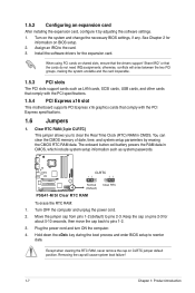
... 2 for information on shared slots, ensure that the drivers support "Share IRQ" or that comply with the PCI Express specifications. 1.6 Jumpers 1. CLRTC 12 23 P5G41-M SI Normal (Default) P5G41-M SI Clear RTC RAM Clear RTC To erase the RTC RAM: 1. 1.5.2 Configuring an expansion card After installing the expansion card, configure it by erasing the...
... 2 for information on shared slots, ensure that the drivers support "Share IRQ" or that comply with the PCI Express specifications. 1.6 Jumpers 1. CLRTC 12 23 P5G41-M SI Normal (Default) P5G41-M SI Clear RTC RAM Clear RTC To erase the RTC RAM: 1. 1.5.2 Configuring an expansion card After installing the expansion card, configure it by erasing the...

User Manual
Page 17
... computer from S3 and S4 sleep modes (no power to clear the CMOS RTC RAM data. ASUS P5G41-M SI 1-8 For system failure due to default values. 2. USBPW1-4 12 23 +5V +5VSB (Default) USBPW5-8 P5G41-M SI 12 23 +5V +5VSB (Default) P5G41-M SI USB Device Wake Up • The USB device wake-up the computer by pressing a key... power, then reboot the system, the BIOS automatically resets parameter settings to overclocking, use the CPU Parameter Recall (C.P.R.) feature. KBPWR 12 23 +5V +5VSB (Default) P5G41-M SI P5G41-M SI Keyboard Power Setting 3.
... computer from S3 and S4 sleep modes (no power to clear the CMOS RTC RAM data. ASUS P5G41-M SI 1-8 For system failure due to default values. 2. USBPW1-4 12 23 +5V +5VSB (Default) USBPW5-8 P5G41-M SI 12 23 +5V +5VSB (Default) P5G41-M SI USB Device Wake Up • The USB device wake-up the computer by pressing a key... power, then reboot the system, the BIOS automatically resets parameter settings to overclocking, use the CPU Parameter Recall (C.P.R.) feature. KBPWR 12 23 +5V +5VSB (Default) P5G41-M SI P5G41-M SI Keyboard Power Setting 3.
User Manual
Page 19
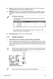
... CRT and isn't compatible with DVI-I. 11. CPU_FAN GND CPU FAN PWR CPU FAN IN CPU FAN PWM P5G41-M SI CHA_FAN GND +12V Rotation P5G41-M SI fan connectors Only the 4-pin CPU fan connector supports the ASUS Q-FAN feature. This port is for a High-Definition Multimedia Interface (HDMI) connector, and is for a PS/2 keyboard. 1.7.2 Internal.... 10. Dual display output support • This table indicates that the black wire of each cable matches the ground pin of 1 A ~ 7 A (84 W max.) at +12V. ASUS P5G41-M SI 1-10
... CRT and isn't compatible with DVI-I. 11. CPU_FAN GND CPU FAN PWR CPU FAN IN CPU FAN PWM P5G41-M SI CHA_FAN GND +12V Rotation P5G41-M SI fan connectors Only the 4-pin CPU fan connector supports the ASUS Q-FAN feature. This port is for a High-Definition Multimedia Interface (HDMI) connector, and is for a PS/2 keyboard. 1.7.2 Internal.... 10. Dual display output support • This table indicates that the black wire of each cable matches the ground pin of 1 A ~ 7 A (84 W max.) at +12V. ASUS P5G41-M SI 1-10
User Manual
Page 20
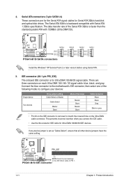
... GND GND RSATA_TXP3 RSATA_TXN3 GND RSATA_RXP3 RSATA_RXN3 GND GND RSATA_TXP2 RSATA_TXN2 GND RSATA_RXP2 RSATA_RXN2 GND GND RSATA_TXP1 RSATA_TXN1 GND RSATA_RXP1 RSATA_RXN1 GND P5G41-M SI SATA connectors Install the Windows® XP Service Pack 2 or later version before using Serial ATA. 3. Connect the blue connector...-Select or Master Cable-Select Master Slave Mode of the Serial ATA 3Gb/s is for Ultra DMA 100/66/33 IDE devices. P5G41-M SI IDE connector 1-11 Chapter 1: Product introduction 2. This prevents incorrect insertion when you connect the IDE cable. • Use the ...
... GND GND RSATA_TXP3 RSATA_TXN3 GND RSATA_RXP3 RSATA_RXN3 GND GND RSATA_TXP2 RSATA_TXN2 GND RSATA_RXP2 RSATA_RXN2 GND GND RSATA_TXP1 RSATA_TXN1 GND RSATA_RXP1 RSATA_RXN1 GND P5G41-M SI SATA connectors Install the Windows® XP Service Pack 2 or later version before using Serial ATA. 3. Connect the blue connector...-Select or Master Cable-Select Master Slave Mode of the Serial ATA 3Gb/s is for Ultra DMA 100/66/33 IDE devices. P5G41-M SI IDE connector 1-11 Chapter 1: Product introduction 2. This prevents incorrect insertion when you connect the IDE cable. • Use the ...
User Manual
Page 21
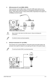
... bracket (COM1) is purchased separately. 5. USB+5V USB_P8USB_P8+ GND NC USB+5V USB_P6USB_P6+ GND NC P5G41-M SI USB56 PIN 1 USB78 PIN 1 USB+5V USB_P7USB_P7+ GND USB+5V USB_P5USB_P5+ GND P5G41-M SI USB2.0 connectors Never connect a 1394 cable to 480Mbps connection speed. The USB 2.0 module is purchased separately... connectors, then install the module to a slot opening at the back of the system chassis. COM1 PIN 1 P5G41-M SI P5G41-M SI Serial port (COM1) connector ASUS P5G41-M SI 1-12 4. USB connectors (10-1 pin USB56, USB78) These connectors are for a serial (COM) port.
... bracket (COM1) is purchased separately. 5. USB+5V USB_P8USB_P8+ GND NC USB+5V USB_P6USB_P6+ GND NC P5G41-M SI USB56 PIN 1 USB78 PIN 1 USB+5V USB_P7USB_P7+ GND USB+5V USB_P5USB_P5+ GND P5G41-M SI USB2.0 connectors Never connect a 1394 cable to 480Mbps connection speed. The USB 2.0 module is purchased separately... connectors, then install the module to a slot opening at the back of the system chassis. COM1 PIN 1 P5G41-M SI P5G41-M SI Serial port (COM1) connector ASUS P5G41-M SI 1-12 4. USB connectors (10-1 pin USB56, USB78) These connectors are for a serial (COM) port.

User Manual
Page 22
... receive stereo audio input from the power supply are for an ATX power supply. CD Right Audio Channel GND GND Left Audio Channel P5G41-M SI P5G41-M SI Internal audio connector 1-13 Chapter 1: Product introduction The system may become unstable or may not boot up if the power is inadequate.... Power Supply Wattage Calculator at least 15 A on +12 V and that the 20-pin power plug can provide at http://support.asus. Optical drive audio in only one orientation. Find the proper orientation and push down firmly until the connectors completely fit. com/PowerSupplyCalculator/...
... receive stereo audio input from the power supply are for an ATX power supply. CD Right Audio Channel GND GND Left Audio Channel P5G41-M SI P5G41-M SI Internal audio connector 1-13 Chapter 1: Product introduction The system may become unstable or may not boot up if the power is inadequate.... Power Supply Wattage Calculator at least 15 A on +12 V and that the 20-pin power plug can provide at http://support.asus. Optical drive audio in only one orientation. Find the proper orientation and push down firmly until the connectors completely fit. com/PowerSupplyCalculator/...
User Manual
Page 23
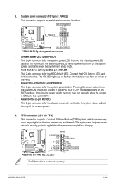
...the system is ON turns the system OFF. • Reset button (2-pin RESET) This 2-pin connector is for the system power button. ASUS P5G41-M SI 1-14 Connect the chassis power LED cable to the HDD. • Power/Soft-off the system power. 9. TPM connector (20-1 pin ...) This 2-pin connector is for system reboot without turning off button (2-pin PWRBTN) This 2-pin connector is purchased separately. Ground Reset P5G41-M SI HD_LED RESET P5G41-M SI System panel connector • System power LED (2-pin PLED) This 2-pin connector is for the chassis-mounted reset button for the HDD...
...the system is ON turns the system OFF. • Reset button (2-pin RESET) This 2-pin connector is for the system power button. ASUS P5G41-M SI 1-14 Connect the chassis power LED cable to the HDD. • Power/Soft-off the system power. 9. TPM connector (20-1 pin ...) This 2-pin connector is for system reboot without turning off button (2-pin PWRBTN) This 2-pin connector is purchased separately. Ground Reset P5G41-M SI HD_LED RESET P5G41-M SI System panel connector • System power LED (2-pin PLED) This 2-pin connector is for the chassis-mounted reset button for the HDD...
User Manual
Page 24
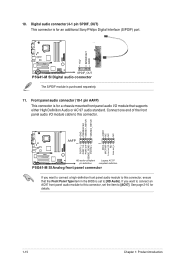
... 1 MIC2 MICPWR Line out_R NC Line out_L PORT1 L PORT1 R PORT2 R SENSE_SEND PORT2 L P5G41-M SI HD-audio-compliant Legacy AC'97 pin definition compliant definition P5G41-M SI Analog front panel connector If you want to connect a high-definition front panel audio module to...connector, set to this connector. See page 2-10 for an additional Sony/Philips Digital Interface (S/PDIF) port. +5V SPDIFOUT GND P5G41-M SI SPDIF_OUT P5G41-M SI Digital audio connector The S/PDIF module is for details. 1-15 Chapter 1: Product introduction Digital audio connector (4-1 pin SPDIF_OUT) This...
... 1 MIC2 MICPWR Line out_R NC Line out_L PORT1 L PORT1 R PORT2 R SENSE_SEND PORT2 L P5G41-M SI HD-audio-compliant Legacy AC'97 pin definition compliant definition P5G41-M SI Analog front panel connector If you want to connect a high-definition front panel audio module to...connector, set to this connector. See page 2-10 for an additional Sony/Philips Digital Interface (S/PDIF) port. +5V SPDIFOUT GND P5G41-M SI SPDIF_OUT P5G41-M SI Digital audio connector The S/PDIF module is for details. 1-15 Chapter 1: Product introduction Digital audio connector (4-1 pin SPDIF_OUT) This...
User Manual
Page 25
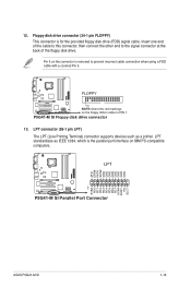
...GND GND GND GND GND GND GND PIN 1 STB# PD0 PD1 PD2 PD3 PD4 PD5 PD6 PD7 ACK# BUSY PE SLCT P5G41-M SI P5G41-M SI Parallel Port Connector ASUS P5G41-M SI 1-16 Floppy disk drive connector (34-1 pin FLOPPY) This connector is removed to prevent incorrect cable connection when using a FDD... cable with a covered Pin 5. 12. P5G41-M SI Floppy disk drive connector 13. LPT connector (26-1 pin LPT) The LPT (Line Printing Terminal...
...GND GND GND GND GND GND GND PIN 1 STB# PD0 PD1 PD2 PD3 PD4 PD5 PD6 PD7 ACK# BUSY PE SLCT P5G41-M SI P5G41-M SI Parallel Port Connector ASUS P5G41-M SI 1-16 Floppy disk drive connector (34-1 pin FLOPPY) This connector is removed to prevent incorrect cable connection when using a FDD... cable with a covered Pin 5. 12. P5G41-M SI Floppy disk drive connector 13. LPT connector (26-1 pin LPT) The LPT (Line Printing Terminal...

User Manual
Page 27
...the installation. Place the support DVD in Windows® environment. The Drivers menu appears. 2. Click the Utilities tab, then click ASUS Update. 3. Updating the BIOS To update the BIOS: 1. From the dropdown list, select Update BIOS from the Open window, ...ASUS Update utility. 2. Locate the BIOS file from a file, then click Next. 3. Copy the original motherboard BIOS using this utility. Quit all Windows® applications before you to manage, save, and update the motherboard BIOS in the optical drive. Installing ASUS Update To install ASUS Update: 1. ASUS P5G41-M SI...
...the installation. Place the support DVD in Windows® environment. The Drivers menu appears. 2. Click the Utilities tab, then click ASUS Update. 3. Updating the BIOS To update the BIOS: 1. From the dropdown list, select Update BIOS from the Open window, ...ASUS Update utility. 2. Locate the BIOS file from a file, then click Next. 3. Copy the original motherboard BIOS using this utility. Quit all Windows® applications before you to manage, save, and update the motherboard BIOS in the optical drive. Installing ASUS Update To install ASUS Update: 1. ASUS P5G41-M SI...