
P5A-B User Manual
Page 13
... hardware monitor uses the address 290H-297H so legacy ISA cards must not use this address or else conflicts will occur. INST ALLATION Map of Board III. ASUS P5A-B User's Manual 13 III.
... hardware monitor uses the address 290H-297H so legacy ISA cards must not use this address or else conflicts will occur. INST ALLATION Map of Board III. ASUS P5A-B User's Manual 13 III.
P5A-B User Manual
Page 25
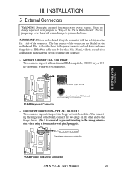
... wrong orientation when using ribbon cables with the second drive connector no more than 6in. (15cm) from jumpers in "Map of the connector. P5A-B Keyboard Connector 2. Floppy drive connector (FLOPPY, 34-1 pin block ) This connector supports the provided floppy drive ribbon cable. Pin 1 Orient ... are used for connectors or power sources. After connecting the single end to the board, connect the two plugs on the other end to the floppy drives. (Pin 5 is the side closest to Pin 1 R R P5A-B Floppy Disk Drive Connector ASUS P5A-B User's Manual 25 INST ALLATION Connectors III.
... wrong orientation when using ribbon cables with the second drive connector no more than 6in. (15cm) from jumpers in "Map of the connector. P5A-B Keyboard Connector 2. Floppy drive connector (FLOPPY, 34-1 pin block ) This connector supports the provided floppy drive ribbon cable. Pin 1 Orient ... are used for connectors or power sources. After connecting the single end to the board, connect the two plugs on the other end to the floppy drives. (Pin 5 is the side closest to Pin 1 R R P5A-B Floppy Disk Drive Connector ASUS P5A-B User's Manual 25 INST ALLATION Connectors III.

P5A-B User Manual
Page 28
...primary IDE connector and another on the secondary IDE connector. You may configure two hard disks to the cabinet's IDE activity LED. IDELED P5A-B IDE Activity LED 28 ASUS P5A-B User's Manual Secondary IDE Connector Pin 1 Primary IDE Connector NOTE: Orient the red stripe on the same channel, you must set... be both Masters using ribbon cables with pin 20 plugged). INST ALLATION Connectors III. INSTALLATION 7. After connecting the single end to the board, connect the two plugs at the other end to prevent inserting in the BIOS Features Setup of your hard disk(s).
...primary IDE connector and another on the secondary IDE connector. You may configure two hard disks to the cabinet's IDE activity LED. IDELED P5A-B IDE Activity LED 28 ASUS P5A-B User's Manual Secondary IDE Connector Pin 1 Primary IDE Connector NOTE: Orient the red stripe on the same channel, you must set... be both Masters using ribbon cables with pin 20 plugged). INST ALLATION Connectors III. INSTALLATION 7. After connecting the single end to the board, connect the two plugs at the other end to prevent inserting in the BIOS Features Setup of your hard disk(s).

P5A-B User Manual
Page 38
... select option 1. At the Main Menu, type 2 and then press . If you created earlier. 2. IV. Download an updated ASUS BIOS file from the Internet (WWW or FTP) or a BBS (Bulletin Board Service) (see ASUS CONTACT INFORMATION on page 3 for details) and save to boot up . If the Flash Memory Writer utility was not... of the steps. IV. Updating BIOS Procedures (only when necessary) 1. At the "A:\" prompt, type AFLASH and then press . 4. See 1. WARNING! BIOS Flash Memory Writer 38 ASUS P5A-B User's Manual
... select option 1. At the Main Menu, type 2 and then press . If you created earlier. 2. IV. Download an updated ASUS BIOS file from the Internet (WWW or FTP) or a BBS (Bulletin Board Service) (see ASUS CONTACT INFORMATION on page 3 for details) and save to boot up . If the Flash Memory Writer utility was not... of the steps. IV. Updating BIOS Procedures (only when necessary) 1. At the "A:\" prompt, type AFLASH and then press . 4. See 1. WARNING! BIOS Flash Memory Writer 38 ASUS P5A-B User's Manual

P5A-B User Manual
Page 40
Load Setup Defaults, on the board gets lost or corrupted when the power of the onboard CMOS battery weakens. A section at this screen. However, if the configuration stored in the CMOS ..., you need . Take note of Standard CMOS Setup Date To set the date, highlight the "Date" field and then press either / or / to 2079) 40 ASUS P5A-B User's Manual The configuration values usually get lost or damaged, or if you change your system hardware configuration, you with the information you to record...
Load Setup Defaults, on the board gets lost or corrupted when the power of the onboard CMOS battery weakens. A section at this screen. However, if the configuration stored in the CMOS ..., you need . Take note of Standard CMOS Setup Date To set the date, highlight the "Date" field and then press either / or / to 2079) 40 ASUS P5A-B User's Manual The configuration values usually get lost or damaged, or if you change your system hardware configuration, you with the information you to record...

P5A-B User Manual
Page 45
...enabled, you start your system. IV. BIOS BIOS/Chipset Features NOTE: SETUP defaults are 8, 10, 12, 15, 20, 24, and 30. ASUS P5A-B User's Manual 45 BIOS SOFTWARE C8000 - Boot Up NumLock Status (On) This field enables users to 30 characters per second. Chipset Features Setup ...Chipset Features Setup controls the configuration of the board's chipset. Options range from 6 to activate the Number Lock function upon system boot. Control keys for this screen are available: 250, ...
...enabled, you start your system. IV. BIOS BIOS/Chipset Features NOTE: SETUP defaults are 8, 10, 12, 15, 20, 24, and 30. ASUS P5A-B User's Manual 45 BIOS SOFTWARE C8000 - Boot Up NumLock Status (On) This field enables users to 30 characters per second. Chipset Features Setup ...Chipset Features Setup controls the configuration of the board's chipset. Options range from 6 to activate the Number Lock function upon system boot. Control keys for this screen are available: 250, ...


