
Motherboard DIY Troubleshooting Guide
Page 18
® P4V8X-X P4V8X-X Onboard LED SB_PWR1 ON Standby Power OFF Powered Off 1-8
® P4V8X-X P4V8X-X Onboard LED SB_PWR1 ON Standby Power OFF Powered Off 1-8

Motherboard DIY Troubleshooting Guide
Page 30
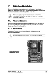
® P4V8X-X ATXPWR1 ATX12V1 Pin 1 +12.0VDC +5VSB PWR_OK COM +5.0VDC COM +5.0VDC COM +3.3VDC +3.3VDC +5.0VDC GND +5.0VDC +12V DC -5.0VDC COM COM COM PS_ON# COM -12.0VDC +3.3VDC GND +12V DC P4V8X-X ATX Power Connectors AGND +5VA BLINE_OUT_R BLINE_OUT_L MIC2 MICPWR Line out_R NC Line out_L 1-20 ® P4V8X-X FP_AUDIO1 P4V8X-X Front Panel Audio Connector
® P4V8X-X ATXPWR1 ATX12V1 Pin 1 +12.0VDC +5VSB PWR_OK COM +5.0VDC COM +5.0VDC COM +3.3VDC +3.3VDC +5.0VDC GND +5.0VDC +12V DC -5.0VDC COM COM COM PS_ON# COM -12.0VDC +3.3VDC GND +12V DC P4V8X-X ATX Power Connectors AGND +5VA BLINE_OUT_R BLINE_OUT_L MIC2 MICPWR Line out_R NC Line out_L 1-20 ® P4V8X-X FP_AUDIO1 P4V8X-X Front Panel Audio Connector

Motherboard DIY Troubleshooting Guide
Page 34
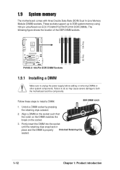
P4V8X-X System Panel Connector • • • • • • 1-24 Power LED Speaker Connector PLED+ PLED+5V Ground Ground Speaker IDE_LED+ IDE_LED- ExtSMI# Ground PWR Ground Reset Ground ® Reset SW P4V8X-X IDE_LED ATX Power SMI Lead Switch* * Requires an ATX power supply.
P4V8X-X System Panel Connector • • • • • • 1-24 Power LED Speaker Connector PLED+ PLED+5V Ground Ground Speaker IDE_LED+ IDE_LED- ExtSMI# Ground PWR Ground Reset Ground ® Reset SW P4V8X-X IDE_LED ATX Power SMI Lead Switch* * Requires an ATX power supply.
Motherboard DIY Troubleshooting Guide
Page 57
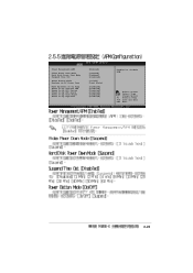
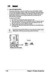
Change Option F1 General Help F10 Save and Exit ESC Exit 2-23 Power Management/APM Video Power Down Mode Hard Disk Power Down Mode Suspend Time Out Power Button Mode Restore on AC Power Loss Wake Up/Power On by Ring Power On by Onboard LAN Power On by PCI Device Power On by RTC Alarm Power On by PS/2 Mouse Power On by Keyboard [Enabled] [Suspend] [Suspend] [Disabled] [On/Off] [Last State] [Disabled] [Disabled] [Disabled] [Disabled] [Disabled] [Disabled] Enabled or disable APM. Select Screen Select Item +-
Change Option F1 General Help F10 Save and Exit ESC Exit 2-23 Power Management/APM Video Power Down Mode Hard Disk Power Down Mode Suspend Time Out Power Button Mode Restore on AC Power Loss Wake Up/Power On by Ring Power On by Onboard LAN Power On by PCI Device Power On by RTC Alarm Power On by PS/2 Mouse Power On by Keyboard [Enabled] [Suspend] [Suspend] [Disabled] [On/Off] [Last State] [Disabled] [Disabled] [Disabled] [Disabled] [Disabled] [Disabled] Enabled or disable APM. Select Screen Select Item +-
P4V8X-X User Manual
Page 4
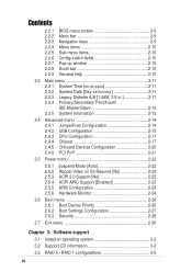
... 2-12 2.3.5 System Information 2-13 2.4 Advanced menu 2-14 2.4.1 JumperFree Configuration 2-14 2.4.2 USB Configuration 2-15 2.4.3 CPU Configuration 2-17 2.4.4 Chipset 2-17 2.4.5 Onboard Devices Configuration 2-20 2.4.6 PCI PnP 2-21 2.5 Power menu 2-22 2.5.1 2.5.2 2.5.3 2.5.4 2.5.5 2.5.6 Suspend Mode [Auto 2-22 Repost Video on S3 Resume [No 2-22 ACPI 2.0 Support [No 2-22 ACPI APIC Support [Enabled 2-23 APM Configuration 2-23...
... 2-12 2.3.5 System Information 2-13 2.4 Advanced menu 2-14 2.4.1 JumperFree Configuration 2-14 2.4.2 USB Configuration 2-15 2.4.3 CPU Configuration 2-17 2.4.4 Chipset 2-17 2.4.5 Onboard Devices Configuration 2-20 2.4.6 PCI PnP 2-21 2.5 Power menu 2-22 2.5.1 2.5.2 2.5.3 2.5.4 2.5.5 2.5.6 Suspend Mode [Auto 2-22 Repost Video on S3 Resume [No 2-22 ACPI 2.0 Support [No 2-22 ACPI APIC Support [Enabled 2-23 APM Configuration 2-23...

P4V8X-X User Manual
Page 6
...your dealer immediately. • To avoid short circuits, keep paper clips, screws, and staples away from the motherboard, ensure that the power cables for the devices are unplugged before the signal cables are using an adpater or extension cord. Safety information Electrical safety • To ...prevent electrical shock hazard, disconnect the power cable from the electrical outlet before relocating the system. • When adding or removing devices to fix it by yourself. If you...
...your dealer immediately. • To avoid short circuits, keep paper clips, screws, and staples away from the motherboard, ensure that the power cables for the devices are unplugged before the signal cables are using an adpater or extension cord. Safety information Electrical safety • To ...prevent electrical shock hazard, disconnect the power cable from the electrical outlet before relocating the system. • When adding or removing devices to fix it by yourself. If you...
P4V8X-X User Manual
Page 9
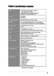
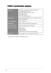
P4V8X-X specifications summary CPU Chipset Front Side Bus (FSB) Memory Expansion slots Storage Audio LAN USB AI Overclocking Special features Back panel I/O Socket 478 for Intel&#... CPU and Memory voltage adjustable SFS (Stepless Frequency Selection) at 1 MHz increment Adjustable FSB/DDR ratio ASUS C.P.R. (CPU Parameter Recall) Power Loss Restart ASUS C.P.R. (CPU Parameter Recall) support S/PDIF out interface ASUS EZ Flash CrashFree BIOS 2 ASUS MyLogo2 1 x Parallel port 1 x Serial port 1 x PS/2 keyboard port 1 x PS/2 mouse port 4 x USB 2.0 ports 1 x S/PDIF out 1 x RJ-45 port...
P4V8X-X specifications summary CPU Chipset Front Side Bus (FSB) Memory Expansion slots Storage Audio LAN USB AI Overclocking Special features Back panel I/O Socket 478 for Intel&#... CPU and Memory voltage adjustable SFS (Stepless Frequency Selection) at 1 MHz increment Adjustable FSB/DDR ratio ASUS C.P.R. (CPU Parameter Recall) Power Loss Restart ASUS C.P.R. (CPU Parameter Recall) support S/PDIF out interface ASUS EZ Flash CrashFree BIOS 2 ASUS MyLogo2 1 x Parallel port 1 x Serial port 1 x PS/2 keyboard port 1 x PS/2 mouse port 4 x USB 2.0 ports 1 x S/PDIF out 1 x RJ-45 port...
P4V8X-X User Manual
Page 10
...P4V8X-X specifications summary Internal I/O BIOS features Industry standard Manageability Power Requirement Support CD contents Form Factor 2 x USB 2.0 connector for 4 additional USB ports CPU/Chassis fan connectors 20-pin/4-pin ATX 12V power connectors CD/AUX connectors Game/MIDI connector 10-1 pin front panel connector 4Mb Flash ROM, AMI BIOS, ACPI, PnP, DMI2.0, ASUS... EZ Flash, ASUS MyLogo2 PCI 2.2, USB 2.0/1.1 DMI 2.0, WOL/WOR by PME, chassis intrusion ATX power supply (with 4-pin 12V plug) Device drivers ASUS PC Probe ASUS LiveUpdate Trend Micro™ PC-...
...P4V8X-X specifications summary Internal I/O BIOS features Industry standard Manageability Power Requirement Support CD contents Form Factor 2 x USB 2.0 connector for 4 additional USB ports CPU/Chassis fan connectors 20-pin/4-pin ATX 12V power connectors CD/AUX connectors Game/MIDI connector 10-1 pin front panel connector 4Mb Flash ROM, AMI BIOS, ACPI, PnP, DMI2.0, ASUS... EZ Flash, ASUS MyLogo2 PCI 2.2, USB 2.0/1.1 DMI 2.0, WOL/WOR by PME, chassis intrusion ATX power supply (with 4-pin 12V plug) Device drivers ASUS PC Probe ASUS LiveUpdate Trend Micro™ PC-...
P4V8X-X User Manual
Page 12
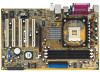
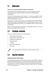
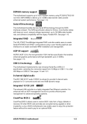
.... 1.3 Special features Latest processor technology The motherboard supports the Intel® Pentium® 4 processor with support for the following items. ASUS P4V8X-X motherboard ASUS P4V8X-X series support CD UltraDMA 133/100/66 cable Floppy disk cable I/O shield Bag of extra jumper caps User Guide If any of computing...! The CPU features the Intel Hyper-Threading Technology and a new power design that allows up to 3GB of system memory with PC3200/...
.... 1.3 Special features Latest processor technology The motherboard supports the Intel® Pentium® 4 processor with support for the following items. ASUS P4V8X-X motherboard ASUS P4V8X-X series support CD UltraDMA 133/100/66 cable Floppy disk cable I/O shield Bag of extra jumper caps User Guide If any of computing...! The CPU features the Intel Hyper-Threading Technology and a new power design that allows up to 3GB of system memory with PC3200/...
P4V8X-X User Manual
Page 13
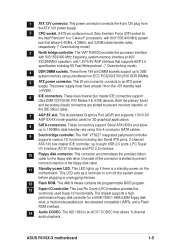
The SATA specification allows for thinner, more flexible cables with an ACPI management function to provide efficient power management for advanced operating systems. CrashFree BIOS 2 CrashFree BIOS 2 allows users to restore BIOS ...AGP8X (AGP 3.0) is enhanced with lower pin count, reduced voltage requirement, up to pay for an optional ROM. ASUS motherboards now enable users to enjoy this protection feature without the need to 150 MB/s data transfer rate, and software...user interface for an easier and faster RAID installation and management. See page 1-12. ASUS P4V8X-X motherboard 1-3
The SATA specification allows for thinner, more flexible cables with an ACPI management function to provide efficient power management for advanced operating systems. CrashFree BIOS 2 CrashFree BIOS 2 allows users to restore BIOS ...AGP8X (AGP 3.0) is enhanced with lower pin count, reduced voltage requirement, up to pay for an optional ROM. ASUS motherboards now enable users to enjoy this protection feature without the need to 150 MB/s data transfer rate, and software...user interface for an easier and faster RAID installation and management. See page 1-12. ASUS P4V8X-X motherboard 1-3
P4V8X-X User Manual
Page 15
... I /O functionality. This Low Pin Count (LPC) interface provides the commonly used Super I /O controller. ASUS P4V8X-X motherboard 1-5 This power connector connects the 4-pin 12V plug from the ATX 12V power supply. 2 CPU socket. The VIA® P4X533 provides the processor interface with 800*/533/400 MHz system... processors, with 800*/533/400 MHz frequency, system memory interface at least 1A on the motherboard. One side of the connector is a standby power on the +5V standby lead (+5VSB). 6 IDE connectors. A 478-pin surface mount, Zero Insertion Force (ZIF) socket for 3D graphical ...
... I /O functionality. This Low Pin Count (LPC) interface provides the commonly used Super I /O controller. ASUS P4V8X-X motherboard 1-5 This power connector connects the 4-pin 12V plug from the ATX 12V power supply. 2 CPU socket. The VIA® P4X533 provides the processor interface with 800*/533/400 MHz system... processors, with 800*/533/400 MHz frequency, system memory interface at least 1A on the motherboard. One side of the connector is a standby power on the +5V standby lead (+5VSB). 6 IDE connectors. A 478-pin surface mount, Zero Insertion Force (ZIF) socket for 3D graphical ...
P4V8X-X User Manual
Page 18
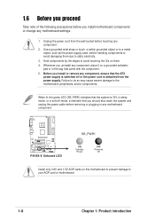
...Before you proceed Take note of the following precautions before you install motherboard components or change any motherboard component. ® P4V8X-X P4V8X-X Onboard LED SB_PWR1 ON Standby Power OFF Powered Off Install only 0.8V and 1.5V AGP cards on them due to the motherboard, peripherals, and/or components. Before... you install or remove any component. 2. Unplug the power cord from the power supply. When lit, the green LED (SB_PWR) indicates that the system is ON, in sleep mode, or in soft-off ...
...Before you proceed Take note of the following precautions before you install motherboard components or change any motherboard component. ® P4V8X-X P4V8X-X Onboard LED SB_PWR1 ON Standby Power OFF Powered Off Install only 0.8V and 1.5V AGP cards on them due to the motherboard, peripherals, and/or components. Before... you install or remove any component. 2. Unplug the power cord from the power supply. When lit, the green LED (SB_PWR) indicates that the system is ON, in sleep mode, or in soft-off ...
P4V8X-X User Manual
Page 19
...components. 1.7.1 Placement direction When installing the motherboard, make sure that you install the motherboard, study the configuration of the chassis ASUS P4V8X-X motherboard 1-9 Failure to the chassis. Do not overtighten the screws! The motherboard uses the ATX form factor that the motherboard...to secure the motherboard to do so may damage the motherboard. Place this side towards the rear of your chassis to unplug the power cord before installing or removing the motherboard. 1.7 Motherboard installation Before you place it . Make sure to ensure that measures 12 ...
...components. 1.7.1 Placement direction When installing the motherboard, make sure that you install the motherboard, study the configuration of the chassis ASUS P4V8X-X motherboard 1-9 Failure to the chassis. Do not overtighten the screws! The motherboard uses the ATX form factor that the motherboard...to secure the motherboard to do so may damage the motherboard. Place this side towards the rear of your chassis to unplug the power cord before installing or removing the motherboard. 1.7 Motherboard installation Before you place it . Make sure to ensure that measures 12 ...
P4V8X-X User Manual
Page 22
... to unplug the power supply before adding or removing DIMMs or other system components. Unlock a DIMM socket by pressing the retaining clips outward. 2. Align a DIMM on the socket such that the notch on the DIMM matches the break on the socket. 3. DIMM1 DIMM2 DIMM3 104 Pins 80 Pins ® P4V8X-X P4V8X-X 184-Pin...
... to unplug the power supply before adding or removing DIMMs or other system components. Unlock a DIMM socket by pressing the retaining clips outward. 2. Align a DIMM on the socket such that the notch on the DIMM matches the break on the socket. 3. DIMM1 DIMM2 DIMM3 104 Pins 80 Pins ® P4V8X-X P4V8X-X 184-Pin...
P4V8X-X User Manual
Page 26
... in CMOS. Removing the cap will cause system boot failure! ® P4V8X-X P4V8X-X Clear RTC RAM CLRTC1 12 Normal (Default) 23 Clear CMOS 1-16 Chapter 1: Product introduction To erase the RTC RAM: 1. Turn OFF the computer and unplug the power cord. 2. You can clear the CMOS memory of date, time, and... move the cap back to clear the Real Time Clock (RTC) RAM in CMOS, that include system setup information such as system passwords, is powered by erasing the CMOS RTC RAM data. Hold down the key during the boot process and enter BIOS setup to pins 2-3. 1.11 Jumper 1. Plug...
... in CMOS. Removing the cap will cause system boot failure! ® P4V8X-X P4V8X-X Clear RTC RAM CLRTC1 12 Normal (Default) 23 Clear CMOS 1-16 Chapter 1: Product introduction To erase the RTC RAM: 1. Turn OFF the computer and unplug the power cord. 2. You can clear the CMOS memory of date, time, and... move the cap back to clear the Real Time Clock (RTC) RAM in CMOS, that include system setup information such as system passwords, is powered by erasing the CMOS RTC RAM data. Hold down the key during the boot process and enter BIOS setup to pins 2-3. 1.11 Jumper 1. Plug...
P4V8X-X User Manual
Page 27
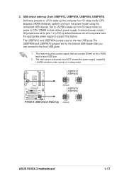
... from S1 sleep mode (CPU stopped, DRAM refreshed, system running in low power mode) using the connected USB devices. USBPW12 USBPW34 12 23 +5V (Default) +5VSB ® P4V8X-X USBPW78 USBPW56 12 23 +5V P4V8X-X USB Device Wake Up (Default) +5VSB ASUS P4V8X-X motherboard 1-17 The USBPW12 and USBPW34 jumpers are for the rear USB ports...
... from S1 sleep mode (CPU stopped, DRAM refreshed, system running in low power mode) using the connected USB devices. USBPW12 USBPW34 12 23 +5V (Default) +5VSB ® P4V8X-X USBPW78 USBPW56 12 23 +5V P4V8X-X USB Device Wake Up (Default) +5VSB ASUS P4V8X-X motherboard 1-17 The USBPW12 and USBPW34 jumpers are for the rear USB ports...
P4V8X-X User Manual
Page 30
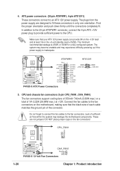
... +5.0VDC +12V DC -5.0VDC COM COM COM PS_ON# COM -12.0VDC +3.3VDC GND +12V DC P4V8X-X ATX Power Connectors 5. CPU_FAN1 GND +12V Rotation ® P4V8X-X CHA_FAN1 Rotation +12V GND P4V8X-X 12-Volt Fan Connectors 1-20 Chapter 1: Product introduction ATX power connectors (20-pin ATXPWR1, 4-pin ATX12V1) These connectors connect to the fan connectors on the...
... +5.0VDC +12V DC -5.0VDC COM COM COM PS_ON# COM -12.0VDC +3.3VDC GND +12V DC P4V8X-X ATX Power Connectors 5. CPU_FAN1 GND +12V Rotation ® P4V8X-X CHA_FAN1 Rotation +12V GND P4V8X-X 12-Volt Fan Connectors 1-20 Chapter 1: Product introduction ATX power connectors (20-pin ATXPWR1, 4-pin ATX12V1) These connectors connect to the fan connectors on the...
P4V8X-X User Manual
Page 33
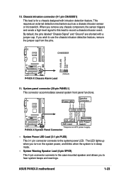
... event. The LED lights up when you to the case-mounted speaker and allows you turn on the system power, and blinks when the system is for a chassis designed with a jumper cap. ASUS P4V8X-X motherboard 1-23 System panel connector (20-pin PANEL1) This connector accommodates several system front panel functions. ExtSMI# Ground PWR...
... event. The LED lights up when you to the case-mounted speaker and allows you turn on the system power, and blinks when the system is for a chassis designed with a jumper cap. ASUS P4V8X-X motherboard 1-23 System panel connector (20-pin PANEL1) This connector accommodates several system front panel functions. ExtSMI# Ground PWR...
P4V8X-X User Manual
Page 34
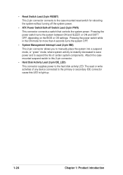
...pin connector allows you to manually place the system into a suspend mode, or "green" mode, where system activity is instantly decreased to save power and to expand the life of any device connected to the primary or secondary IDE connector cause this 2-pin connector. • Hard Disk Activity... Lead (2-pin IDE_LED) This connector supplies power to light up. 1-24 Chapter 1: Product introduction Pressing the power switch turns the system between ON and SLEEP, or ON and SOFT OFF, depending on the BIOS or OS ...
...pin connector allows you to manually place the system into a suspend mode, or "green" mode, where system activity is instantly decreased to save power and to expand the life of any device connected to the primary or secondary IDE connector cause this 2-pin connector. • Hard Disk Activity... Lead (2-pin IDE_LED) This connector supplies power to light up. 1-24 Chapter 1: Product introduction Pressing the power switch turns the system between ON and SLEEP, or ON and SOFT OFF, depending on the BIOS or OS ...
P4V8X-X User Manual
Page 39
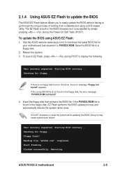
...Power-On Self Tests (POST). If there is not found in the drive, the error message "Floppy not found !" 4. If the correct BIOS file is no floppy disk found in the floppy disk, the error message "P4V8XX.ROM not found !" Checking for floppy... Visit the ASUS website (www.asus... or reset the system while updating the BIOS! Reading file "p4v8xx.rom". Insert the floppy disk that contains the BIOS file. ASUS P4V8X-X motherboard 2-5 To update the BIOS using a DOS-based utility. Checking for floppy... User recovery requested. Starting BIOS recovery... Completed...
...Power-On Self Tests (POST). If there is not found in the drive, the error message "Floppy not found !" 4. If the correct BIOS file is no floppy disk found in the floppy disk, the error message "P4V8XX.ROM not found !" Checking for floppy... Visit the ASUS website (www.asus... or reset the system while updating the BIOS! Reading file "p4v8xx.rom". Insert the floppy disk that contains the BIOS file. ASUS P4V8X-X motherboard 2-5 To update the BIOS using a DOS-based utility. Checking for floppy... User recovery requested. Starting BIOS recovery... Completed...


