P4T User Manual
Page 2
... product name and revision number are represented by any of the means indicated on the product itself. Product Name: ASUS P4T Manual Revision: 1.07 E820 Release Date: July 2001 2 ASUS P4T User's Manual Product warranty or service will not be extended if: (1) the product is authorized in writing by the purchaser ..., or translated into any language in any form or by the third digit in the manual revision number. For previous or updated manuals, BIOS, drivers, or product release information, contact ASUS at http://www.asus.com.tw or through any means, except documentation kept by...
... product name and revision number are represented by any of the means indicated on the product itself. Product Name: ASUS P4T Manual Revision: 1.07 E820 Release Date: July 2001 2 ASUS P4T User's Manual Product warranty or service will not be extended if: (1) the product is authorized in writing by the purchaser ..., or translated into any language in any form or by the third digit in the manual revision number. For previous or updated manuals, BIOS, drivers, or product release information, contact ASUS at http://www.asus.com.tw or through any means, except documentation kept by...

P4T User Manual
Page 4
... the Computer System 43 4.1.2 Updating BIOS Procedures 44 4.2 BIOS Setup Program 47 4.2.1 BIOS Menu Bar 48 4.2.2 Legend Bar 48 4.3 Main Menu 50 4.3.1 Primary & Secondary Master/Slave 51 4.3.2 Keyboard Features 54 4.4 Advanced Menu 56 4.4.1 4.4.2 4.4.3 4.4.4 Chip Configuration 60 I/O Device Configuration 62 PCI Configuration 64 Shadow Configuration 65 4 ASUS P4T User's Manual FEATURES 8 2.1 The ASUS P4T 8 2.2 P4T Motherboard Components 12 3. INTRODUCTION...
... the Computer System 43 4.1.2 Updating BIOS Procedures 44 4.2 BIOS Setup Program 47 4.2.1 BIOS Menu Bar 48 4.2.2 Legend Bar 48 4.3 Main Menu 50 4.3.1 Primary & Secondary Master/Slave 51 4.3.2 Keyboard Features 54 4.4 Advanced Menu 56 4.4.1 4.4.2 4.4.3 4.4.4 Chip Configuration 60 I/O Device Configuration 62 PCI Configuration 64 Shadow Configuration 65 4 ASUS P4T User's Manual FEATURES 8 2.1 The ASUS P4T 8 2.2 P4T Motherboard Components 12 3. INTRODUCTION...
P4T User Manual
Page 5
...68 4.5.2 Hardware Monitor 70 4.6 Boot Menu 71 4.7 Exit Menu 73 5. APPENDIX 109 7.1 Glossary 109 INDEX 113 ASUS P4T User's Manual 5 SOFTWARE REFERENCE 95 6.1 ASUS PC Probe 95 6.2 ASUS Update 100 6.3 YAMAHA XGPlayer 101 6.4 CyberLink PowerPlayer SE 105 6.5 CyberLink VideoLive Mail 106 7. SOFTWARE SETUP 75 ... P4T Motherboard Support CD 76 5.4 INF Update Utility for Intel 850 Chipset 78 5.5 Intel Ultra ATA Storage Driver 79 5.6 Intel LDCM Administrator Setup 81 5.7 Intel LDCM Client Setup 83 5.8 ASUS BIOS Flash Utility for LDCM 6.0 84 5.9 ASUS PC Probe Vx.xx 84 5.10 ASUS ...
...68 4.5.2 Hardware Monitor 70 4.6 Boot Menu 71 4.7 Exit Menu 73 5. APPENDIX 109 7.1 Glossary 109 INDEX 113 ASUS P4T User's Manual 5 SOFTWARE REFERENCE 95 6.1 ASUS PC Probe 95 6.2 ASUS Update 100 6.3 YAMAHA XGPlayer 101 6.4 CyberLink PowerPlayer SE 105 6.5 CyberLink VideoLive Mail 106 7. SOFTWARE SETUP 75 ... P4T Motherboard Support CD 76 5.4 INF Update Utility for Intel 850 Chipset 78 5.5 Intel Ultra ATA Storage Driver 79 5.6 Intel LDCM Administrator Setup 81 5.7 Intel LDCM Client Setup 83 5.8 ASUS BIOS Flash Utility for LDCM 6.0 84 5.9 ASUS PC Probe Vx.xx 84 5.10 ASUS ...
P4T User Manual
Page 7
... the BIOS Intructions on setting up the included software Reference material for (1) 5.25" and (2) 3.5" floppy disk drives (2) ASUS C-RIMM Continuity RIMM (1) ASUS 2-port USB connector set with bracket (1) I/O port bracket (1) Bag of spare jumpers (1) Support drivers and utilities (1) This Motherboard User's Manual (1) CPU Heatsink Retention Module Optional Items ASUS IrDA-compliant infrared module ASUS P4T User...
... the BIOS Intructions on setting up the included software Reference material for (1) 5.25" and (2) 3.5" floppy disk drives (2) ASUS C-RIMM Continuity RIMM (1) ASUS 2-port USB connector set with bracket (1) I/O port bracket (1) Bag of spare jumpers (1) Support drivers and utilities (1) This Motherboard User's Manual (1) CPU Heatsink Retention Module Optional Items ASUS IrDA-compliant infrared module ASUS P4T User...
P4T User Manual
Page 8
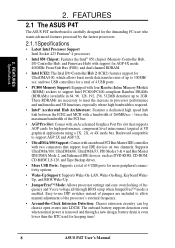
... (ICH2) features support for a total of 266MB/sec - The onboard battery supports detection even when normal power is removed and through BIOS setup when JumperFree™ mode is even lower than the RTC used for AGP 4X mode; 400MHz Front Side Bus (FSB); twice the... an onboard PCI Bus Master IDE controller with support for keeping time! 8 ASUS P4T User's Manual 2. These RDRAMs are included to allow manual adjustment of up to 100MB/ sec; FEATURES 2.1 The ASUS P4T The ASUS P4T motherboard is required. • Intel® Accelerated Hub Architecture: Features a dedicated...
... (ICH2) features support for a total of 266MB/sec - The onboard battery supports detection even when normal power is removed and through BIOS setup when JumperFree™ mode is even lower than the RTC used for AGP 4X mode; 400MHz Front Side Bus (FSB); twice the... an onboard PCI Bus Master IDE controller with support for keeping time! 8 ASUS P4T User's Manual 2. These RDRAMs are included to allow manual adjustment of up to 100MB/ sec; FEATURES 2.1 The ASUS P4T The ASUS P4T motherboard is required. • Intel® Accelerated Hub Architecture: Features a dedicated...
P4T User Manual
Page 9
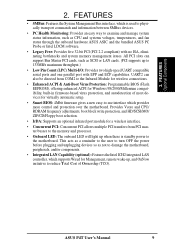
... also be directed from COM2 to the Infrared Module for wireless connections. • Enhanced ACPI & Anti-Boot Virus Protection: Programmable BIOS (Flash EEPROM), offering enhanced ACPI for a wireless interface. • Concurrent PCI: Concurrent PCI allows multiple PCI transfers from PCI ...an optional infrared port module for Windows 98/2000/Millenium compatibility, built-in firmware-based virus protection, and autodetection of Ownership (TCO). ASUS P4T User's Manual 9 2. FEATURES Optional Components 2. This acts as a reminder to the user to turn OFF the power before plugging and...
... also be directed from COM2 to the Infrared Module for wireless connections. • Enhanced ACPI & Anti-Boot Virus Protection: Programmable BIOS (Flash EEPROM), offering enhanced ACPI for a wireless interface. • Concurrent PCI: Concurrent PCI allows multiple PCI transfers from PCI ...an optional infrared port module for Windows 98/2000/Millenium compatibility, built-in firmware-based virus protection, and autodetection of Ownership (TCO). ASUS P4T User's Manual 9 2. FEATURES Optional Components 2. This acts as a reminder to the user to turn OFF the power before plugging and...
P4T User Manual
Page 10
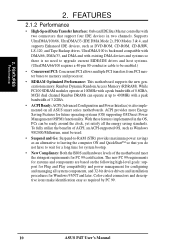
...100/66, UltraDMA/33 (IDE DMA Mode 2), PIO Modes 3 & 4, and supports Enhanced IDE devices, such as required by PC 99. 10 ASUS P4T User's Manual ACPI provides more Energy Saving Features for Windows 95/NT and later. Color-coded connectors and descriptive icons make identification easy as DVD-...Bus Master controller with two connectors that you do not have to wait for a long time for system bootup. • New Compliancy: Both the BIOS and hardware levels of 0.8GB/s, MCH dual channel Rambus DRAMs can be enabled.) • Concurrent PCI: Concurrent PCI allows multiple PCI transfers from PCI...
...100/66, UltraDMA/33 (IDE DMA Mode 2), PIO Modes 3 & 4, and supports Enhanced IDE devices, such as required by PC 99. 10 ASUS P4T User's Manual ACPI provides more Energy Saving Features for Windows 95/NT and later. Color-coded connectors and descriptive icons make identification easy as DVD-...Bus Master controller with two connectors that you do not have to wait for a long time for system bootup. • New Compliancy: Both the BIOS and hardware levels of 0.8GB/s, MCH dual channel Rambus DRAMs can be enabled.) • Concurrent PCI: Concurrent PCI allows multiple PCI transfers from PCI...
P4T User Manual
Page 11
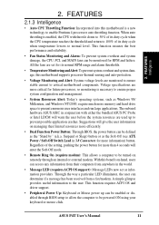
...Power Button: Through BIOS, the power button can be powered ON using your keyboard or mouse click. This function requires ACPI OS and driver support. • Peripheral Power Up: Keyboard or Mouse power up to be turned on managing their computers from a fax/modem. ASUS P4T User's Manual 11... thresholds. • Temperature Monitoring andAlert: To prevent system overheat and system damage, this motherboard is enabled, the CPU with either the bundled ASUS PC Probe or Intel LDCM will enter the Soft-Off mode. • Remote Ring On (requires modem): This allows a computer to prevent...
...Power Button: Through BIOS, the power button can be powered ON using your keyboard or mouse click. This function requires ACPI OS and driver support. • Peripheral Power Up: Keyboard or Mouse power up to be turned on managing their computers from a fax/modem. ASUS P4T User's Manual 11... thresholds. • Temperature Monitoring andAlert: To prevent system overheat and system damage, this motherboard is enabled, the CPU with either the bundled ASUS PC Probe or Intel LDCM will enter the Soft-Off mode. • Remote Ring On (requires modem): This allows a computer to prevent...
P4T User Manual
Page 17
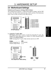
...Disable (Jumper Mode) [1-2] SW1 OFF ON 1 2 3 4 5 6 7 8 9 10 ® P4T P4T JumperFree™ Mode Setting Jumper JumperFree 12 23 JEN ASUS P4T User's Manual 17 Frequency Multiple 3. Frequency Selection 10. Frequency Selection 1) JumperFree™ Mode (JEN) This jumper...8482; mode, all the switches in the OFF position. ® P4T P4T DIP Switches SW1 ON OFF 1. HARDWARE SETUP 3.4 Motherboard Settings Motherboard Frequency Settings (DIP Switches) The motherboard frequency is adjusted through the BIOS setup (see 4.4 Advanced Menu). Frequency Multiple 4. Frequency Multiple 5....
...Disable (Jumper Mode) [1-2] SW1 OFF ON 1 2 3 4 5 6 7 8 9 10 ® P4T P4T JumperFree™ Mode Setting Jumper JumperFree 12 23 JEN ASUS P4T User's Manual 17 Frequency Multiple 3. Frequency Selection 10. Frequency Selection 1) JumperFree™ Mode (JEN) This jumper...8482; mode, all the switches in the OFF position. ® P4T P4T DIP Switches SW1 ON OFF 1. HARDWARE SETUP 3.4 Motherboard Settings Motherboard Frequency Settings (DIP Switches) The motherboard frequency is adjusted through the BIOS setup (see 4.4 Advanced Menu). Frequency Multiple 4. Frequency Multiple 5....
P4T User Manual
Page 21
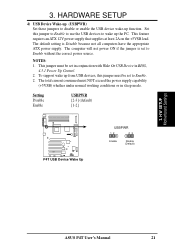
...Enable. 2. This jumper must NOT exceed the power supply capability (+5VSB) whether under normal working conditions or in BIOS, 4.5.1 Power Up Control. 2. H/W SETUP Motherboard Settings ASUS P4T User's Manual 21 To support wake up function. HARDWARE SETUP 4) USB Device Wake-up (USBPWR) Set these ... total current consumed must be set to wake up the PC. NOTES: 1. 3. Setting Disable Enable USBPWR [2-3] (default) [1-2] ® P4T P4T USB Device Wake Up USBPWR 12 23 Enable Disable (Default) 3. This feature requires an ATX 12V power supply that supplies at least 2A ...
...Enable. 2. This jumper must NOT exceed the power supply capability (+5VSB) whether under normal working conditions or in BIOS, 4.5.1 Power Up Control. 2. H/W SETUP Motherboard Settings ASUS P4T User's Manual 21 To support wake up function. HARDWARE SETUP 4) USB Device Wake-up (USBPWR) Set these ... total current consumed must be set to wake up the PC. NOTES: 1. 3. Setting Disable Enable USBPWR [2-3] (default) [1-2] ® P4T P4T USB Device Wake Up USBPWR 12 23 Enable Disable (Default) 3. This feature requires an ATX 12V power supply that supplies at least 2A ...
P4T User Manual
Page 22
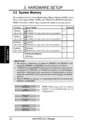
...128MB RDRAM RIMMB2 C-RIMM RIMMB1 128MB RDRAM C-RIMM RIMMA2 RIMMA1 c. 128MB RDRAM RIMMB2 128MB RDRAM RIMMB1 128MB RDRAM 128MB RDRAM RIMMA2 RIMMA1 22 ASUS P4T User's Manual C-RIMM 128MB RDRAM RIMMB2 RIMMB1 NOTE: When using only two memory C-RIMM RIMMA2 modules, it is recommended that they be ... and channel B (RIMMB1 and RIMMB2) must be inserted into RIMMA2 and RIMMB2. H/W SETUP Motherboard Settings 3. NOTE: No hardware or BIOS setup is necessary to avoid breaking the signal lines, which make serial connection in this motherboard. This assures that are required, it is...
...128MB RDRAM RIMMB2 C-RIMM RIMMB1 128MB RDRAM C-RIMM RIMMA2 RIMMA1 c. 128MB RDRAM RIMMB2 128MB RDRAM RIMMB1 128MB RDRAM 128MB RDRAM RIMMA2 RIMMA1 22 ASUS P4T User's Manual C-RIMM 128MB RDRAM RIMMB2 RIMMB1 NOTE: When using only two memory C-RIMM RIMMA2 modules, it is recommended that they be ... and channel B (RIMMB1 and RIMMB2) must be inserted into RIMMA2 and RIMMB2. H/W SETUP Motherboard Settings 3. NOTE: No hardware or BIOS setup is necessary to avoid breaking the signal lines, which make serial connection in this motherboard. This assures that are required, it is...
P4T User Manual
Page 27
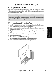
... to do so may need to use . 3. Unplug the system power cord when adding or removing expansion cards or other system components. Change the necessary BIOS settings, if any. (see section 4.4.3 PCI Configuration to the slot with the expansion card and make any necessary hardware settings for the card before installing... support these cards. Keep the screw for the expansion card. 3. 3. Follow the steps in place. 4. Secure the card to change the settings.) 7. H/W SETUP Expansion Cards ASUS P4T User's Manual 27
... to do so may need to use . 3. Unplug the system power cord when adding or removing expansion cards or other system components. Change the necessary BIOS settings, if any. (see section 4.4.3 PCI Configuration to the slot with the expansion card and make any necessary hardware settings for the card before installing... support these cards. Keep the screw for the expansion card. 3. 3. Follow the steps in place. 4. Secure the card to change the settings.) 7. H/W SETUP Expansion Cards ASUS P4T User's Manual 27

P4T User Manual
Page 32
The connector allows the motherboard to connect to the secondary IDE connector. PIN 1 32 ASUS P4T User's Manual RJ-45 Port 3. It is removed to PIN 1. one operating system on an IDE drive and another for 100MByte/sec transfer rates. H/W ...SETUP Connectors 7) Primary (Blue) / Secondary IDE Connectors (Two 40-1pin IDE) These connectors support the provided IDE hard disk ribbon cable. BIOS now supports specific device bootup (see 4.6 Boot Menu). (Pin 20 is recommended that non-UltraDMA/100 devices be both Masters with pin 20 plugged). You...
The connector allows the motherboard to connect to the secondary IDE connector. PIN 1 32 ASUS P4T User's Manual RJ-45 Port 3. It is removed to PIN 1. one operating system on an IDE drive and another for 100MByte/sec transfer rates. H/W ...SETUP Connectors 7) Primary (Blue) / Secondary IDE Connectors (Two 40-1pin IDE) These connectors support the provided IDE hard disk ribbon cable. BIOS now supports specific device bootup (see 4.6 Boot Menu). (Pin 20 is recommended that non-UltraDMA/100 devices be both Masters with pin 20 plugged). You...
P4T User Manual
Page 41
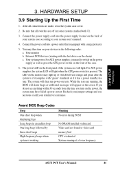
...have failed a power-on test. Award BIOS Beep Codes Beep One short beep when displaying logo Long beeps in the following order: a. 3. Connect the power supply cord into a power outlet that all connections are running at a lower frequency ASUS P4T User's Manual 41 Recheck your jumper settings ...Meaning No error during POST No DRAM installed or detected Video card not found or video card memory bad CPU overheated System running , the BIOS will alarm beeps or additional messages will light when the ATX power switch is equipped with ). 3. HARDWARE SETUP 3.9 Starting Up the ...
...have failed a power-on test. Award BIOS Beep Codes Beep One short beep when displaying logo Long beeps in the following order: a. 3. Connect the power supply cord into a power outlet that all connections are running at a lower frequency ASUS P4T User's Manual 41 Recheck your jumper settings ...Meaning No error during POST No DRAM installed or detected Video card not found or video card memory bad CPU overheated System running , the BIOS will alarm beeps or additional messages will light when the ATX power switch is equipped with ). 3. HARDWARE SETUP 3.9 Starting Up the ...

P4T User Manual
Page 42
... or shutting down your operating system before switching off your computer" will not appear when shutting down with ATX power supplies. 3. H/W SETUP Powering Up 42 ASUS P4T User's Manual NOTE: The message "You can press the ATX power switch after Windows shuts down the computer? 3. Follow the instructions in 4. For ATX power... supplies, you use Windows 9X, click the Start button, click Shut Down, and then click Shut down . BIOS SETUP. * Powering Off your computer: You must first exit or shut down to enter...
... or shutting down your operating system before switching off your computer" will not appear when shutting down with ATX power supplies. 3. H/W SETUP Powering Up 42 ASUS P4T User's Manual NOTE: The message "You can press the ATX power switch after Windows shuts down the computer? 3. Follow the instructions in 4. For ATX power... supplies, you use Windows 9X, click the Start button, click Shut Down, and then click Shut down . BIOS SETUP. * Powering Off your computer: You must first exit or shut down to enter...
P4T User Manual
Page 43
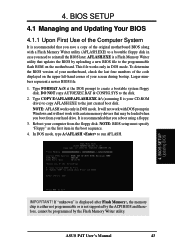
...case you save a copy of the original motherboard BIOS along with a Flash Memory Writer utility (AFLASH.EXE) to reinstall the BIOS later. BIOS SETUP Updating BIOS IMPORTANT! Type COPY E:\AFLASH\AFLASH.EXE A:\ (assuming E is not supported by the ACPI BIOS and therefore, cannot be loaded when you reboot ...in DOS mode. In DOS mode, type A:\AFLASH to the disk. 2. ASUS P4T User's Manual 43 AFLASH.EXE is recommended that updates the BIOS by the Flash Memory Writer utility. 4. To determine the BIOS version of your motherboard, check the last four numbers of your hard drive...
...case you save a copy of the original motherboard BIOS along with a Flash Memory Writer utility (AFLASH.EXE) to reinstall the BIOS later. BIOS SETUP Updating BIOS IMPORTANT! Type COPY E:\AFLASH\AFLASH.EXE A:\ (assuming E is not supported by the ACPI BIOS and therefore, cannot be loaded when you reboot ...in DOS mode. In DOS mode, type A:\AFLASH to the disk. 2. ASUS P4T User's Manual 43 AFLASH.EXE is recommended that updates the BIOS by the Flash Memory Writer utility. 4. To determine the BIOS version of your motherboard, check the last four numbers of your hard drive...
P4T User Manual
Page 44
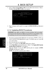
...created earlier. 3. Select 1. Save Current BIOS to the disk you know that the new BIOS revision will solve your problems. Careless updating can result in your new BIOS and the path, for example, A:\XXXXX.XXX, and then press . BIOS SETUP Updating BIOS 44 ASUS P4T User's Manual NOTE: To cancel this operation..., press . 4. Boot from the Main menu and press . Only update your BIOS if you have problems with your...
...created earlier. 3. Select 1. Save Current BIOS to the disk you know that the new BIOS revision will solve your problems. Careless updating can result in your new BIOS and the path, for example, A:\XXXXX.XXX, and then press . BIOS SETUP Updating BIOS 44 ASUS P4T User's Manual NOTE: To cancel this operation..., press . 4. Boot from the Main menu and press . Only update your BIOS if you have problems with your...
P4T User Manual
Page 45
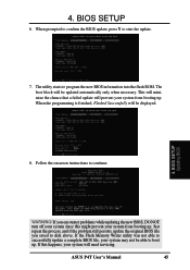
... the process, and if the problem still persists, update the original BIOS file you encounter problems while updating the new BIOS, DO NOT turn off your system since this happens, your system from booting up. ASUS P4T User's Manual 45 If this might prevent your system will be updated... automatically only when necessary. When prompted to confirm the BIOS update, press Y to program the new BIOS information into the flash ROM. The utility starts to...
... the process, and if the problem still persists, update the original BIOS file you encounter problems while updating the new BIOS, DO NOT turn off your system since this happens, your system from booting up. ASUS P4T User's Manual 45 If this might prevent your system will be updated... automatically only when necessary. When prompted to confirm the BIOS update, press Y to program the new BIOS information into the flash ROM. The utility starts to...
P4T User Manual
Page 46
BIOS SETUP Updating BIOS 46 ASUS P4T User's Manual BIOS SETUP (This page was intentionally left blank.) 4. 4.
BIOS SETUP Updating BIOS 46 ASUS P4T User's Manual BIOS SETUP (This page was intentionally left blank.) 4. 4.
P4T User Manual
Page 47
...these changes and record them in the future you with its POST. But do so only if the first two methods fail. BIOS SETUP 4.2 BIOS Setup Program This motherboard supports a programmable EEPROM that the computer can be necessary to reconfigure your system, or prompted to enable ...calling up Setup. This appears during the Power-On Self Test (POST). To access the BIOS Setup program, press the key after the computer has run this utility. BIOS SETUP Program Information ASUS P4T User's Manual 47 For example, you are for reference purposes only and may not reflect ...
...these changes and record them in the future you with its POST. But do so only if the first two methods fail. BIOS SETUP 4.2 BIOS Setup Program This motherboard supports a programmable EEPROM that the computer can be necessary to reconfigure your system, or prompted to enable ...calling up Setup. This appears during the Power-On Self Test (POST). To access the BIOS Setup program, press the key after the computer has run this utility. BIOS SETUP Program Information ASUS P4T User's Manual 47 For example, you are for reference purposes only and may not reflect ...


