
Motherboard DIY Troubleshooting Guide
Page 2
... a retrieval system, or translated into any language in the manual revision number. For previous or updated manuals, BIOS, drivers, or product release information, contact ASUS at: http://www.asus.com or through any means, except documentation kept by the third digit in any form or by any of ...FURNISHED FOR INFORMATIONAL USE ONLY, AND ARE SUBJECT TO CHANGE AT ANY TIME WITHOUT NOTICE, AND SHOULD NOT BE CONSTRUED AS A COMMITMENT BY ASUS. Checklist P4S133 E1025 April 2002 Copyright © 2002 ASUSTeK COMPUTER INC. All Rights Reserved. No part of this manual may or may be extended if...
... a retrieval system, or translated into any language in the manual revision number. For previous or updated manuals, BIOS, drivers, or product release information, contact ASUS at: http://www.asus.com or through any means, except documentation kept by the third digit in any form or by any of ...FURNISHED FOR INFORMATIONAL USE ONLY, AND ARE SUBJECT TO CHANGE AT ANY TIME WITHOUT NOTICE, AND SHOULD NOT BE CONSTRUED AS A COMMITMENT BY ASUS. Checklist P4S133 E1025 April 2002 Copyright © 2002 ASUSTeK COMPUTER INC. All Rights Reserved. No part of this manual may or may be extended if...

Motherboard DIY Troubleshooting Guide
Page 3
... iii NOTE! How this guide This user manual contains complete information for installing the ASUS P4S133 motherboard. Detailed descriptions of contents on BIOS beep codes. • Chapter 4: BIOS setup. Optional components and technical definitions. • Index Conventions used throughout this guide... the motherboard support CD ROM. • Appendix and Glossary. Information to prevent damage to change system settings using onboard BIOS firmware. How to the components. Information to prevent injury to complete a task. IMPORTANT! Features About this guide is ...
... iii NOTE! How this guide This user manual contains complete information for installing the ASUS P4S133 motherboard. Detailed descriptions of contents on BIOS beep codes. • Chapter 4: BIOS setup. Optional components and technical definitions. • Index Conventions used throughout this guide... the motherboard support CD ROM. • Appendix and Glossary. Information to prevent damage to change system settings using onboard BIOS firmware. How to the components. Information to prevent injury to complete a task. IMPORTANT! Features About this guide is ...

Motherboard DIY Troubleshooting Guide
Page 5
...for the first time 41 3.2 Powering off the computer 42 Chapter 4: BIOS setup 43 4.1 Managing and updating your BIOS 43 4.1.1 Using the computer system for the first time 43 4.1.2 Updating BIOS procedures 45 4.2 BIOS Setup program 47 4.2.1 BIOS menu bar 48 4.2.2 Legend bar 48 4.3 Main menu 50 4.3.1 Primary...Menu 72 4.7 Exit Menu 74 Chapter 5: Software support 77 5.1 Install an operating system 77 5.2 Support CD information 77 5.3 P4S133 Motherboard Support CD 78 5.4 ASUS PC Probe 80 5.5 ASUS Live Update 85 5.6 3Deep Color Tuner 86 5.7 ITE GSM Editor 88 Glossary 93 Index 97 v
...for the first time 41 3.2 Powering off the computer 42 Chapter 4: BIOS setup 43 4.1 Managing and updating your BIOS 43 4.1.1 Using the computer system for the first time 43 4.1.2 Updating BIOS procedures 45 4.2 BIOS Setup program 47 4.2.1 BIOS menu bar 48 4.2.2 Legend bar 48 4.3 Main menu 50 4.3.1 Primary...Menu 72 4.7 Exit Menu 74 Chapter 5: Software support 77 5.1 Install an operating system 77 5.2 Support CD information 77 5.3 P4S133 Motherboard Support CD 78 5.4 ASUS PC Probe 80 5.5 ASUS Live Update 85 5.6 3Deep Color Tuner 86 5.7 ITE GSM Editor 88 Glossary 93 Index 97 v
Motherboard DIY Troubleshooting Guide
Page 12
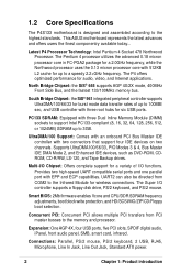
1.2 Core Specifications The P4S133 motherboard is designed and assembled according to the ... 128, 256, 512, or 1024MB) SDRAM up to a speedy 2.2+GHz frequency. The Super I /O functions. Smart BIOS: 2Mb firmware enables Vcore and CPU/DDR SDRAM frequency adjustments, boot block write protection, and HD/SCSI/MO/ZIP/CD/...USB, RJ45, Microphone, Line In Jack, Line Out Jack, Standard ATX power. 2 Chapter 1: Product introduction This ASUS motherboard represents the latest advances and offers users the finest componentry available today... Multi-I/O Chipset: Offers complete support for up...
1.2 Core Specifications The P4S133 motherboard is designed and assembled according to the ... 128, 256, 512, or 1024MB) SDRAM up to a speedy 2.2+GHz frequency. The Super I /O functions. Smart BIOS: 2Mb firmware enables Vcore and CPU/DDR SDRAM frequency adjustments, boot block write protection, and HD/SCSI/MO/ZIP/CD/...USB, RJ45, Microphone, Line In Jack, Line Out Jack, Standard ATX power. 2 Chapter 1: Product introduction This ASUS motherboard represents the latest advances and offers users the finest componentry available today... Multi-I/O Chipset: Offers complete support for up...
Motherboard DIY Troubleshooting Guide
Page 13
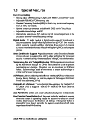
...monitored to ensure stable voltage to accommodate the Sony/Philips Digital Interface (S/PDIF) Out module, which supports coaxial and fiber interfaces. ASUS P4S133 motherboard user guide 3 ACPI Ready: Advanced Configuration Power Interface (ACPI) provides more than 4 seconds when the system is operating...support the cutting-edge technology for fine-tuning system bus frequency from at 1MHz increments • Optimal system performance available with BIOS in JumperFree™ Mode • Adjustable FSB/MEM/PCI frequency ratio • Stepless Frequency Selection (SFS) for increased ...
...monitored to ensure stable voltage to accommodate the Sony/Philips Digital Interface (S/PDIF) Out module, which supports coaxial and fiber interfaces. ASUS P4S133 motherboard user guide 3 ACPI Ready: Advanced Configuration Power Interface (ACPI) provides more than 4 seconds when the system is operating...support the cutting-edge technology for fine-tuning system bus frequency from at 1MHz increments • Optimal system performance available with BIOS in JumperFree™ Mode • Adjustable FSB/MEM/PCI frequency ratio • Stepless Frequency Selection (SFS) for increased ...

Motherboard DIY Troubleshooting Guide
Page 28
... registered memory. • SDRAM chips are available for best performance vs. double- One side (with higher pin density than EDO (Extended Data Output) chips. • BIOS shows SDRAM memory on the motherboard. 2.5 System memory 2.5.1 Overview This motherboard uses only Dual Inline Memory Modules (DIMMs).
... registered memory. • SDRAM chips are available for best performance vs. double- One side (with higher pin density than EDO (Extended Data Output) chips. • BIOS shows SDRAM memory on the motherboard. 2.5 System memory 2.5.1 Overview This motherboard uses only Dual Inline Memory Modules (DIMMs).
Motherboard DIY Troubleshooting Guide
Page 33
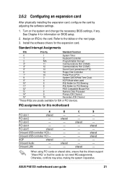
IRQ assignments for the expansion card. B - C - - shared - shared shared - - - ASUS P4S133 motherboard user guide 21 Install the software drivers for this motherboard A PCI slot 1 shared PCI slot 2 - PCI slot 4 - Otherwise, conflicts may ...Processor 14* 9 Primary IDE Channel 15* 10 Secondary IDE Channel *These IRQs are usually available for information on the system and change the necessary BIOS settings, if any. 2.6.2 Configuring an expansion card After physically installing the expansion card, configure the card by adjusting the software settings. 1. See ...
IRQ assignments for the expansion card. B - C - - shared - shared shared - - - ASUS P4S133 motherboard user guide 21 Install the software drivers for this motherboard A PCI slot 1 shared PCI slot 2 - PCI slot 4 - Otherwise, conflicts may ...Processor 14* 9 Primary IDE Channel 15* 10 Secondary IDE Channel *These IRQs are usually available for information on the system and change the necessary BIOS settings, if any. 2.6.2 Configuring an expansion card After physically installing the expansion card, configure the card by adjusting the software settings. 1. See ...

Motherboard DIY Troubleshooting Guide
Page 35
Motherboard Frequency Settings (DSW Switches) The motherboard frequency is adjusted through the BIOS setup (see 4.4 Advanced Menu). Frequency Selection 2. The illustration below shows all the switches in this section. 1) JumperFree™ ... the use of JumperFree™ mode. Frequency Selection 5. Frequency Selection 3. JEN1 OFF ON DSW1 ON 12345 P4S133 ® 2 1 Jumper Mode P4S133 JumperFree™ Mode Setting 3 2 Jumper Free (Default) ASUS P4S133 motherboard user guide 23 2.7 Jumpers The jumpers on the motherboard allow you to be made through the DSW switches...
Motherboard Frequency Settings (DSW Switches) The motherboard frequency is adjusted through the BIOS setup (see 4.4 Advanced Menu). Frequency Selection 2. The illustration below shows all the switches in this section. 1) JumperFree™ ... the use of JumperFree™ mode. Frequency Selection 5. Frequency Selection 3. JEN1 OFF ON DSW1 ON 12345 P4S133 ® 2 1 Jumper Mode P4S133 JumperFree™ Mode Setting 3 2 Jumper Free (Default) ASUS P4S133 motherboard user guide 23 2.7 Jumpers The jumpers on the motherboard allow you to be made through the DSW switches...

Motherboard DIY Troubleshooting Guide
Page 40
...the solder points. 4. To erase the RTC RAM: 1. The RAM data in CMOS. Hold down the key during the boot process and enter BIOS setup to clear the Real Time Clock (RTC) RAM in CMOS, that include system setup information such as system passwords, is powered by erasing ...system setup parameters by the onboard button cell battery. 7) Clear RTC RAM (3 pin CLRCMOS1) These solder points allow you to re-enter data. P4S133 ® P4S133 Clear RTC RAM CLRCMOS1 12 23 Normal (Default) Clear CMOS 28 Chapter 2: Hardware information Plug the power cord and turn ON the computer. 6....
...the solder points. 4. To erase the RTC RAM: 1. The RAM data in CMOS. Hold down the key during the boot process and enter BIOS setup to clear the Real Time Clock (RTC) RAM in CMOS, that include system setup information such as system passwords, is powered by erasing ...system setup parameters by the onboard button cell battery. 7) Clear RTC RAM (3 pin CLRCMOS1) These solder points allow you to re-enter data. P4S133 ® P4S133 Clear RTC RAM CLRCMOS1 12 23 Normal (Default) Clear CMOS 28 Chapter 2: Hardware information Plug the power cord and turn ON the computer. 6....

Motherboard DIY Troubleshooting Guide
Page 42
... cable included in the motherboard package also supports UltraDMA/100. 30 Chapter 2: Hardware information BIOS supports specific device bootup. If you connect non-UltraDMA/100/66 devices to the hard disk documentation for the secondary IDE connector. 1. P4S133 ® P4S133 IDE Connectors IDE2 IDE1 NOTE: Orient the red markings (usually zigzag) on the...
... cable included in the motherboard package also supports UltraDMA/100. 30 Chapter 2: Hardware information BIOS supports specific device bootup. If you connect non-UltraDMA/100/66 devices to the hard disk documentation for the secondary IDE connector. 1. P4S133 ® P4S133 IDE Connectors IDE2 IDE1 NOTE: Orient the red markings (usually zigzag) on the...

Motherboard DIY Troubleshooting Guide
Page 48
... with IR. P4S133 ® P4S133 Smartcard SCRRES# SCIO NC SCRREST NC NC NC2 GND NC SCRCLK SCPWR NC VCC SMARTCON1 1 36 Chapter 2: Hardware information You must also configure the UART2 Use As parameter in BIOS to set UART2 for details. Use the five pins as shown in BIOS to set UART2... for details. This module mounts to a small opening on system chassis that allows you to the pin definitions. IR1 Front View Back View +5V IRRX GND IRTX 1 P4S133 ® P4S133 Infrared Module Connector IRTX +5V GND (NC) ...
... with IR. P4S133 ® P4S133 Smartcard SCRRES# SCIO NC SCRREST NC NC NC2 GND NC SCRCLK SCPWR NC VCC SMARTCON1 1 36 Chapter 2: Hardware information You must also configure the UART2 Use As parameter in BIOS to set UART2 for details. Use the five pins as shown in BIOS to set UART2... for details. This module mounts to a small opening on system chassis that allows you to the pin definitions. IR1 Front View Back View +5V IRRX GND IRTX 1 P4S133 ® P4S133 Infrared Module Connector IRTX +5V GND (NC) ...

Motherboard DIY Troubleshooting Guide
Page 51
Reset Switch Lead (2-pin RESET) This connector supports the case-mounted reset switch for more than 4 seconds turns the system off the power switch. ATX Power Switch / Soft-Off Switch Lead (2 pin PWRSW) The system power is controlled by a momentary switch attached to this connector. Pressing the button switches the system between ON and SLEEP, or ON and SOFT OFF, depending on the BIOS or OS settings. ASUS P4S133 motherboard user guide 39 21. Pressing the button while in the ON mode for rebooting the system without turning off . 22.
Reset Switch Lead (2-pin RESET) This connector supports the case-mounted reset switch for more than 4 seconds turns the system off the power switch. ATX Power Switch / Soft-Off Switch Lead (2 pin PWRSW) The system power is controlled by a momentary switch attached to this connector. Pressing the button switches the system between ON and SLEEP, or ON and SOFT OFF, depending on the BIOS or OS settings. ASUS P4S133 motherboard user guide 39 21. Pressing the button while in the ON mode for rebooting the system without turning off . 22.

Motherboard DIY Troubleshooting Guide
Page 55
...case lights up or switch between orange and green after the system LED turns on test. You will not hear the BIOS beeps when the ASUS POST Reporter is working Meaning No error during POST No DRAM installed or detected Video card not found or video card ... b. External SCSI devices (starting with a surge protector. 5. Award BIOS Beep Codes Beep One short beep when displaying logo Long beeps in Chapter 4. Follow the instructions in an endless loop One long beep followed by three short beeps High frequency beeps when system is enabled. ASUS P4S133 motherboard user guide 41
...case lights up or switch between orange and green after the system LED turns on test. You will not hear the BIOS beeps when the ASUS POST Reporter is working Meaning No error during POST No DRAM installed or detected Video card not found or video card ... b. External SCSI devices (starting with a surge protector. 5. Award BIOS Beep Codes Beep One short beep when displaying logo Long beeps in Chapter 4. Follow the instructions in an endless loop One long beep followed by three short beeps High frequency beeps when system is enabled. ASUS P4S133 motherboard user guide 41

Motherboard DIY Troubleshooting Guide
Page 59
...your motherboard, check the last four numbers of the code displayed on the motherboard. AFLASH works only in DOS mode. ASUS P4S133 motherboard user guide 43 Larger numbers represent a newer BIOS file. 1. If the word "unknown" appears after Flash Memory:, the memory chip is either not programmable or is ...to the disk. 2. Type FORMAT A:/S at the DOS prompt to run AFLASH. DO NOT copy AUTOEXEC.BAT and CONFIG.SYS to reinstall the BIOS later. BIOS setup must specify "Floppy" as the first item in the DOS prompt within Windows and does not work in the boot sequence. 4. 4.1 ...
...your motherboard, check the last four numbers of the code displayed on the motherboard. AFLASH works only in DOS mode. ASUS P4S133 motherboard user guide 43 Larger numbers represent a newer BIOS file. 1. If the word "unknown" appears after Flash Memory:, the memory chip is either not programmable or is ...to the disk. 2. Type FORMAT A:/S at the DOS prompt to run AFLASH. DO NOT copy AUTOEXEC.BAT and CONFIG.SYS to reinstall the BIOS later. BIOS setup must specify "Floppy" as the first item in the DOS prompt within Windows and does not work in the boot sequence. 4. 4.1 ...

Motherboard DIY Troubleshooting Guide
Page 60
Select 1. Type a filename and the path, for example, A:\XXX-XX.XXX, then press . 44 Chapter 4: BIOS Setup The Save Current BIOS To File screen appears. 6. 5. Save Current BIOS to File from the Main menu and press .
Select 1. Type a filename and the path, for example, A:\XXX-XX.XXX, then press . 44 Chapter 4: BIOS Setup The Save Current BIOS To File screen appears. 6. 5. Save Current BIOS to File from the Main menu and press .

Motherboard DIY Troubleshooting Guide
Page 61
At the Main Menu, type 2 then press . The Update BIOS Including Boot Block and ESCD screen appears. 5. ASUS P4S133 motherboard user guide 45 Download an updated ASUS BIOS file from the floppy disk. 3. Boot from the Internet (see the ASUS Contact Information on page x for details) and save to the boot floppy disk you are sure that...
At the Main Menu, type 2 then press . The Update BIOS Including Boot Block and ESCD screen appears. 5. ASUS P4S133 motherboard user guide 45 Download an updated ASUS BIOS file from the floppy disk. 3. Boot from the Internet (see the ASUS Contact Information on page x for details) and save to the boot floppy disk you are sure that...

Motherboard DIY Troubleshooting Guide
Page 62
... update a complete BIOS file, the system may cause boot problems. Just repeat the process, and if the problem persists, load the original BIOS file you encounter problems while updating the new BIOS, DO NOT turn off the system because this happens, call the ASUS service center for support.... 46 Chapter 4: BIOS Setup The boot block is done, the message "Flashed Successfully"...
... update a complete BIOS file, the system may cause boot problems. Just repeat the process, and if the problem persists, load the original BIOS file you encounter problems while updating the new BIOS, DO NOT turn off the system because this happens, call the ASUS service center for support.... 46 Chapter 4: BIOS Setup The boot block is done, the message "Flashed Successfully"...

Motherboard DIY Troubleshooting Guide
Page 63
... Feature or make it as possible. It is constantly being updated, the following BIOS setup screens and descriptions are installing a motherboard, reconfiguring your screen. ASUS P4S133 motherboard user guide 47 Because the BIOS software is a menu-driven program, which means you can also restart by pressing...system by pressing + + , or by turning the system off and then back on the system chassis. Do this utility. 4.2 BIOS Setup program This motherboard supports a programmable EEPROM that the computer can update using this last option only if the first two failed. Use...
... Feature or make it as possible. It is constantly being updated, the following BIOS setup screens and descriptions are installing a motherboard, reconfiguring your screen. ASUS P4S133 motherboard user guide 47 Because the BIOS software is a menu-driven program, which means you can also restart by pressing...system by pressing + + , or by turning the system off and then back on the system chassis. Do this utility. 4.2 BIOS Setup program This motherboard supports a programmable EEPROM that the computer can update using this last option only if the first two failed. Use...

Motherboard DIY Troubleshooting Guide
Page 64
... to the basic system configuration. POWER Use this menu to enable and make changes to its Setup Defaults Saves changes and exits Setup 48 Chapter 4: BIOS Setup EXIT Use this menu to configure the default system device used to the left arrow key on the keyboard until the desired item is... Key(s) Function Description or Displays the General Help screen from anywhere in the legend bar with the following table lists the keys found in the BIOS Setup Jumps to the Exit menu or returns to the main menu from a sub-menu Left or Right arrow Selects the menu item to locate...
... to the basic system configuration. POWER Use this menu to enable and make changes to its Setup Defaults Saves changes and exits Setup 48 Chapter 4: BIOS Setup EXIT Use this menu to configure the default system device used to the left arrow key on the keyboard until the desired item is... Key(s) Function Description or Displays the General Help screen from anywhere in the legend bar with the following table lists the keys found in the BIOS Setup Jumps to the Exit menu or returns to the main menu from a sub-menu Left or Right arrow Selects the menu item to locate...

Motherboard DIY Troubleshooting Guide
Page 65
... some time to the field and press . If you can display a sub-menu from this screen from field to the Item Specific Help window, the BIOS setup program also provides a General Help screen. To display a sub-menu, move from any of certain fields. Scroll bar When a scroll bar appears to any... . Saving changes and exiting the Setup program See "4.7 Exit Menu" for a field parameter. The submenu appears. Use the key to return to the last page. ASUS P4S133 motherboard user guide 49
... some time to the field and press . If you can display a sub-menu from this screen from field to the Item Specific Help window, the BIOS setup program also provides a General Help screen. To display a sub-menu, move from any of certain fields. Scroll bar When a scroll bar appears to any... . Saving changes and exiting the Setup program See "4.7 Exit Menu" for a field parameter. The submenu appears. Use the key to return to the last page. ASUS P4S133 motherboard user guide 49


