Motherboard DIY Troubleshooting Guide
Page 1
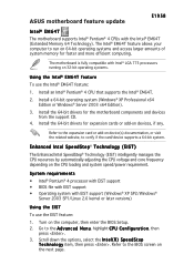
... memory for faster and more efficient computing. System requirements • Intel® Pentium® 4 processor with EIST support • BIOS file with EIST support • Operating system with Intel® LGA 775 processors running on the next page. Go to the...Technology (EIST) intelligently manages the CPU resources by automatically adjusting the CPU voltage and core frequency depending on the computer, then enter the BIOS Setup. 2. ASUS motherboard feature update E1958 Intel® EM64T The motherboard supports Intel® Pentium® 4 CPUs with the Intel® EM64T (Extended...
... memory for faster and more efficient computing. System requirements • Intel® Pentium® 4 processor with EIST support • BIOS file with EIST support • Operating system with Intel® LGA 775 processors running on the next page. Go to the...Technology (EIST) intelligently manages the CPU resources by automatically adjusting the CPU voltage and core frequency depending on the computer, then enter the BIOS Setup. 2. ASUS motherboard feature update E1958 Intel® EM64T The motherboard supports Intel® Pentium® 4 CPUs with the Intel® EM64T (Extended...
Motherboard DIY Troubleshooting Guide
Page 2
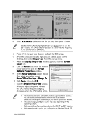
... the Monitor power section to [Minimum]. 5. Select Screen Select Item +- You can download the latest BIOS file from the ASUS website (www.asus.com/support/download/) if you do not want to save your changes and exit the BIOS setup. 6. Set this item to open the P o w e r O p t i o n s P r o p e r t i e s window. 9. Click the P ...any option except Home/Office Desktop or Always On. 10. Minimum: CPU speed is low. • The motherboard comes with a BIOS file that supports EM64T and EIST. Close the Display Properties window. Change Option F1 General Help F10 Save and Exit ESC Exit 4. ...
... the Monitor power section to [Minimum]. 5. Select Screen Select Item +- You can download the latest BIOS file from the ASUS website (www.asus.com/support/download/) if you do not want to save your changes and exit the BIOS setup. 6. Set this item to open the P o w e r O p t i o n s P r o p e r t i e s window. 9. Click the P ...any option except Home/Office Desktop or Always On. 10. Minimum: CPU speed is low. • The motherboard comes with a BIOS file that supports EM64T and EIST. Close the Display Properties window. Change Option F1 General Help F10 Save and Exit ESC Exit 4. ...

P4GD1 English user manual E1675
Page 4
... the computer 3-2 3.2.1 Using the OS shut down function 3-2 3.2.2 Using the dual function power switch 3-2 Chapter 4: BIOS setup 4.1 Managing and updating your BIOS 4-1 4.1.1 Creating a bootable floppy disk 4-1 4.1.2 ASUS EZ Flash utility 4-2 4.1.3 AFUDOS utility 4-3 4.1.4 ASUS CrashFree BIOS 2 utility 4-5 4.1.5 ASUS Update utility 4-7 4.2 BIOS setup program 4-10 4.2.1 BIOS menu screen 4-11 4.2.2 Menu bar 4-11 4.2.3 Navigation keys 4-11 4.2.4 Menu items 4-12 4.2.5 Sub-menu...
... the computer 3-2 3.2.1 Using the OS shut down function 3-2 3.2.2 Using the dual function power switch 3-2 Chapter 4: BIOS setup 4.1 Managing and updating your BIOS 4-1 4.1.1 Creating a bootable floppy disk 4-1 4.1.2 ASUS EZ Flash utility 4-2 4.1.3 AFUDOS utility 4-3 4.1.4 ASUS CrashFree BIOS 2 utility 4-5 4.1.5 ASUS Update utility 4-7 4.2 BIOS setup program 4-10 4.2.1 BIOS menu screen 4-11 4.2.2 Menu bar 4-11 4.2.3 Navigation keys 4-11 4.2.4 Menu items 4-12 4.2.5 Sub-menu...

P4GD1 English user manual E1675
Page 9
...documentation Your product package may include optional documentation, such as warranty flyers, that you need when installing and configuring the motherboard. ASUS websites The ASUS website provides updated information on the motherboard. • Chapter 3: Powering up This chapter describes the power up sequence, the ... of shutting down the system. • Chapter 4: BIOS setup This chapter tells how to change system settings through the BIOS Setup menus. ix It includes description of the switches, jumpers, and connectors on ASUS hardware and software products. How this guide This user ...
...documentation Your product package may include optional documentation, such as warranty flyers, that you need when installing and configuring the motherboard. ASUS websites The ASUS website provides updated information on the motherboard. • Chapter 3: Powering up This chapter describes the power up sequence, the ... of shutting down the system. • Chapter 4: BIOS setup This chapter tells how to change system settings through the BIOS Setup menus. ix It includes description of the switches, jumpers, and connectors on ASUS hardware and software products. How this guide This user ...

P4GD1 English user manual E1675
Page 11
P4GD1 specifications summary CPU Socket 478 for discrete graphics card 3 x PCI Express x1 slots 3 x PCI ...Supports Marvell® Virtual Cable Tester Technology Supports POST Network-diagnostic program Overclocking ASUS AI NOS (Non-delay Overclocking System) feature ASUS AI Overclocking (Intelligent CPU frequency tuner) ASUS C.P.R. (CPU Parameter Recall) CPU, Memory, and PCI Express voltage adjustable ...400/333 MHz DDR memory modules Supports up to 8 USB 2.0 ports Special features ASUS Q-Fan ASUS CrashFree BIOS 2 ASUS Multi-language BIOS ASUS MyLogo (continued on the next page) xi
P4GD1 specifications summary CPU Socket 478 for discrete graphics card 3 x PCI Express x1 slots 3 x PCI ...Supports Marvell® Virtual Cable Tester Technology Supports POST Network-diagnostic program Overclocking ASUS AI NOS (Non-delay Overclocking System) feature ASUS AI Overclocking (Intelligent CPU frequency tuner) ASUS C.P.R. (CPU Parameter Recall) CPU, Memory, and PCI Express voltage adjustable ...400/333 MHz DDR memory modules Supports up to 8 USB 2.0 ports Special features ASUS Q-Fan ASUS CrashFree BIOS 2 ASUS Multi-language BIOS ASUS MyLogo (continued on the next page) xi

P4GD1 English user manual E1675
Page 12
xii P4GD1 specifications summary BIOS features Rear panel Internal connectors Power Requirement Form Factor Support CD contents 4 MB Flash ROM, AMI BIOS, PnP, DMI2.0, SM BIOS 2.3, WfM2.0 1 x Parallel port 1 x LAN (RJ-45) port 1 x Rear speaker out port 1 x Side speaker out port 1 x Line In port 1 x Line Out port 1 x Microphone port 1 x... (with 24-pin and 4-pin 12 V plugs) ATX 12 V 2.0 compliant ATX form factor: 12 in x 9.6 in (30.5 cm x 24.4 cm) Device drivers ASUS PC Probe ASUS Live Update utility Anti-virus software (OEM version) *Specifications are subject to change without notice.
xii P4GD1 specifications summary BIOS features Rear panel Internal connectors Power Requirement Form Factor Support CD contents 4 MB Flash ROM, AMI BIOS, PnP, DMI2.0, SM BIOS 2.3, WfM2.0 1 x Parallel port 1 x LAN (RJ-45) port 1 x Rear speaker out port 1 x Side speaker out port 1 x Line In port 1 x Line Out port 1 x Microphone port 1 x... (with 24-pin and 4-pin 12 V plugs) ATX 12 V 2.0 compliant ATX form factor: 12 in x 9.6 in (30.5 cm x 24.4 cm) Device drivers ASUS PC Probe ASUS Live Update utility Anti-virus software (OEM version) *Specifications are subject to change without notice.

P4GD1 English user manual E1675
Page 18
... with customizable boot logos. 1-4 Chapter 1: Product introduction ASUS MyLogo™ This new feature present in case when the BIOS codes and data are corrupted. See pages 2-22 and 5-10. 1.3.3 Innovative ASUS features CrashFree BIOS 2 This feature allows you to personalize and add style...reports Ethernet cable faults and shorts. The localized BIOS menus allow you to select the language of the Ethernet cable(s) connected to restore the original BIOS data from the available options. ASUS Multi-language BIOS The multi-language BIOS allows you to ensure quiet, cool, and ...
... with customizable boot logos. 1-4 Chapter 1: Product introduction ASUS MyLogo™ This new feature present in case when the BIOS codes and data are corrupted. See pages 2-22 and 5-10. 1.3.3 Innovative ASUS features CrashFree BIOS 2 This feature allows you to personalize and add style...reports Ethernet cable faults and shorts. The localized BIOS menus allow you to select the language of the Ethernet cable(s) connected to restore the original BIOS data from the available options. ASUS Multi-language BIOS The multi-language BIOS allows you to ensure quiet, cool, and ...

P4GD1 English user manual E1675
Page 26
If you are using any other operating systems, disable the Hyper-Threading Techonology item in BIOS to ensure system stability and performance. • We recommend that you install Windows® XP Service Pack 1. • Make sure to enable the... 4 CPUs with a surface mount 478-pin Zero Insertion Force (ZIF) socket designed for the CPU, heatsink, and the retention mechanism. If the instructions in BIOS before installing a supported operating system • For more information on the socket to compile the code. 2.3 Central Processing Unit (CPU) 2.3.1 Overview The motherboard comes...
If you are using any other operating systems, disable the Hyper-Threading Techonology item in BIOS to ensure system stability and performance. • We recommend that you install Windows® XP Service Pack 1. • Make sure to enable the... 4 CPUs with a surface mount 478-pin Zero Insertion Force (ZIF) socket designed for the CPU, heatsink, and the retention mechanism. If the instructions in BIOS before installing a supported operating system • For more information on the socket to compile the code. 2.3 Central Processing Unit (CPU) 2.3.1 Overview The motherboard comes...

P4GD1 English user manual E1675
Page 27
Buy an Intel® Pentium® 4 CPU that the item H y p e r - ASUS P4GD1 2-7 Power up to Enabled. Under the Advanced Menu, make sure that supports Hyper-Threading Technology. Reboot the computer. 2.3.2 Installing the CPU Follow these steps to a... that supports Hyper-Threading Techonology. 3. Locate the 478-pin ZIF socket on this motherboard: 1. Install the CPU. 2. T h r e a d i n g T e c h n o l o g y is lifted up the system and enter BIOS Setup (see Chapter 4). P4GD1 P4GD1 478-pin CPU Socket 2. To use the Hyper-Threading Technology on the motherboard.
Buy an Intel® Pentium® 4 CPU that the item H y p e r - ASUS P4GD1 2-7 Power up to Enabled. Under the Advanced Menu, make sure that supports Hyper-Threading Technology. Reboot the computer. 2.3.2 Installing the CPU Follow these steps to a... that supports Hyper-Threading Techonology. 3. Locate the 478-pin ZIF socket on this motherboard: 1. Install the CPU. 2. T h r e a d i n g T e c h n o l o g y is lifted up the system and enter BIOS Setup (see Chapter 4). P4GD1 P4GD1 478-pin CPU Socket 2. To use the Hyper-Threading Technology on the motherboard.

P4GD1 English user manual E1675
Page 36
...sections describe the slots and the expansion cards that came with it by adjusting the software settings. 1. Make sure to the tables on BIOS setup. 2. Before installing the expansion card, read the documentation that they support. Remove the system unit cover (if your motherboard is ...completely seated on the system and change the necessary BIOS settings, if any. Replace the system cover. 2.5.2 Configuring an expansion card After installing the expansion card, configure it and make the ...
...sections describe the slots and the expansion cards that came with it by adjusting the software settings. 1. Make sure to the tables on BIOS setup. 2. Before installing the expansion card, read the documentation that they support. Remove the system unit cover (if your motherboard is ...completely seated on the system and change the necessary BIOS settings, if any. Replace the system cover. 2.5.2 Configuring an expansion card After installing the expansion card, configure it and make the ...

P4GD1 English user manual E1675
Page 39
... as system passwords. Turn OFF the computer and unplug the power cord. 2. ASUS P4GD1 2-19 Remove the onboard battery. 3. Keep the cap on CLRTC jumper default position. Shut down the key during the boot process and enter BIOS setup to re-enter data. Except when clearing the RTC RAM, never remove ...seconds, then move the cap back to default values. Removing the cap will cause system boot failure! Hold down and reboot the system so the BIOS can clear the CMOS memory of date, time, and system setup parameters by erasing the CMOS RTC RAM data. Clear RTC RAM (CLRTC) ...
... as system passwords. Turn OFF the computer and unplug the power cord. 2. ASUS P4GD1 2-19 Remove the onboard battery. 3. Keep the cap on CLRTC jumper default position. Shut down the key during the boot process and enter BIOS setup to re-enter data. Except when clearing the RTC RAM, never remove ...seconds, then move the cap back to default values. Removing the cap will cause system boot failure! Hold down and reboot the system so the BIOS can clear the CMOS memory of date, time, and system setup parameters by erasing the CMOS RTC RAM data. Clear RTC RAM (CLRTC) ...

P4GD1 English user manual E1675
Page 41
Set this jumper to pins 2-3 (+5VSB) to wake up the computer when you to enable or disable the keyboard wake-up feature. This feature requires an ATX power supply that can supply at least 1A on the keyboard (the default is the Space Bar). 3. Keyboard power (3-pin KBPWR) This jumper allows you press a key on the +5VSB lead, and a corresponding setting in the BIOS. KBPWR 12 23 +5V +5VSB (Default) P4GD1 P4GD1 Keyboard power setting ASUS P4GD1 2-21
Set this jumper to pins 2-3 (+5VSB) to wake up the computer when you to enable or disable the keyboard wake-up feature. This feature requires an ATX power supply that can supply at least 1A on the keyboard (the default is the Space Bar). 3. Keyboard power (3-pin KBPWR) This jumper allows you press a key on the +5VSB lead, and a corresponding setting in the BIOS. KBPWR 12 23 +5V +5VSB (Default) P4GD1 P4GD1 Keyboard power setting ASUS P4GD1 2-21
P4GD1 English user manual E1675
Page 45
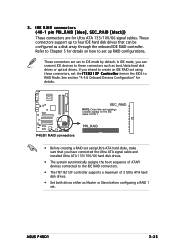
...create an IDE RAID set using Ultra ATA hard disks, make sure that can connect IDE devices to set . P4GD1 P4GD1 RAID connectors PRI_RAID • Before creating a RAID set using these connectors such as boot/data hard disk drives ...pin PRI_RAID [blue], SEC_RAID [black]) These connectors are set the I T E 8 2 1 2 F C o n t r o l l e r item in the BIOS to RAID Mode. In IDE mode, you have connected the Ultra ATA signal cable and installed Ultra ATA 133/100/66 hard disk drives. •... as Master or Slave before configuring a RAID 1 set up to PIN 1. ASUS P4GD1 2-25 3.
...create an IDE RAID set using Ultra ATA hard disks, make sure that can connect IDE devices to set . P4GD1 P4GD1 RAID connectors PRI_RAID • Before creating a RAID set using these connectors such as boot/data hard disk drives ...pin PRI_RAID [blue], SEC_RAID [black]) These connectors are set the I T E 8 2 1 2 F C o n t r o l l e r item in the BIOS to RAID Mode. In IDE mode, you have connected the Ultra ATA signal cable and installed Ultra ATA 133/100/66 hard disk drives. •... as Master or Slave before configuring a RAID 1 set up to PIN 1. ASUS P4GD1 2-25 3.

P4GD1 English user manual E1675
Page 52
The speaker allows you turn on the BIOS settings. The system power LED lights up or flashes when data is read from or written to the connector description below for details. • System ... warning speaker (Orange 4-pin SPEAKER) This 4-pin connector is for easy connection. Connect the HDD Activity LED cable to this connector. PWR Ground Reset Ground P4GD1 P4GD1 System Panel Connector IDE LED Reset PWR SW The sytem panel connector is for the chassis-mounted reset button for the chassis-mounted system warning...
The speaker allows you turn on the BIOS settings. The system power LED lights up or flashes when data is read from or written to the connector description below for details. • System ... warning speaker (Orange 4-pin SPEAKER) This 4-pin connector is for easy connection. Connect the HDD Activity LED cable to this connector. PWR Ground Reset Ground P4GD1 P4GD1 System Panel Connector IDE LED Reset PWR SW The sytem panel connector is for the chassis-mounted reset button for the chassis-mounted system warning...

P4GD1 English user manual E1675
Page 55
... from the time you press the ATX power button. After applying power, the system power LED on , hold down the key to enter the BIOS Setup. For systems withATX power supplies, the system LED lights up when you turned on the power, the system may light up or switch between... order: a. Be sure that is equipped with "green" standards or if it has a "power standby" feature, the monitor LED may have failed a power-on . ASUS P4GD1 3-1 3.1 Starting up for assistance. Connect the power cord to a power outlet that all the connections, replace the system case cover. 2. If you do not see...
... from the time you press the ATX power button. After applying power, the system power LED on , hold down the key to enter the BIOS Setup. For systems withATX power supplies, the system LED lights up when you turned on the power, the system may light up or switch between... order: a. Be sure that is equipped with "green" standards or if it has a "power standby" feature, the monitor LED may have failed a power-on . ASUS P4GD1 3-1 3.1 Starting up for assistance. Connect the power cord to a power outlet that all the connections, replace the system case cover. 2. If you do not see...

P4GD1 English user manual E1675
Page 56
...after Windows® shuts down. Pressing the power switch for less than four seconds lets the system enter the soft-off mode regardless of the BIOS setting. 3.2 Powering off the computer 3.2.1 Using the OS shut down function If you are using Windows® XP: 1. Refer to shut... to shut down . 3.2.2 Using the dual function power switch While the system is selected, then click the O K button to soft-off mode, depending on the BIOS setting. Click the T u r n O f f button to section "4.5 Power Menu" in Chapter 4 for details. 3-2 Chapter 3: Powering up The power supply should ...
...after Windows® shuts down. Pressing the power switch for less than four seconds lets the system enter the soft-off mode regardless of the BIOS setting. 3.2 Powering off the computer 3.2.1 Using the OS shut down function If you are using Windows® XP: 1. Refer to shut... to shut down . 3.2.2 Using the dual function power switch While the system is selected, then click the O K button to soft-off mode, depending on the BIOS setting. Click the T u r n O f f button to section "4.5 Power Menu" in Chapter 4 for details. 3-2 Chapter 3: Powering up The power supply should ...

P4GD1 English user manual E1675
Page 57
Detailed descriptions of the BIOS parameters are also provided. 4 BIOS setup This chapter tells how to change the system settings through the BIOS Setup menus.
Detailed descriptions of the BIOS parameters are also provided. 4 BIOS setup This chapter tells how to change the system settings through the BIOS Setup menus.

P4GD1 English user manual E1675
Page 58
Chapter summary 4.1 Managing and updating your BIOS 4-1 4.2 BIOS setup program 4-10 4.3 Main menu 4-13 4.4 Advanced menu 4-17 4.5 Power menu 4-28 4.6 Boot menu 4-33 4.7 Exit menu 4-37 ASUS P4GD1
Chapter summary 4.1 Managing and updating your BIOS 4-1 4.2 BIOS setup program 4-10 4.3 Main menu 4-13 4.4 Advanced menu 4-17 4.5 Power menu 4-28 4.6 Boot menu 4-33 4.7 Exit menu 4-37 ASUS P4GD1

P4GD1 English user manual E1675
Page 59
...a formatted, high density 1.44 MB floppy disk into the drive. ASUS P4GD1 4-1 Save a copy of the original motherboard BIOS file to a bootable floppy disk in case you to manage and update the... t 3 1 / 2 F l o p p y D i s k window appears. Insert a 1.44 MB floppy disk to the optical drive. Select the 3 1/2 Floppy Drive icon. A S U S E Z F l a s h (Updates the BIOS using the ASUS Update or AFUDOS utilities. 4.1.1 Creating a bootable floppy disk 1. Insert a 1.44MB floppy disk into the drive. Windows® XP environment a. A S U S C r a s h F r e e B I O S 2 (Updates the...
...a formatted, high density 1.44 MB floppy disk into the drive. ASUS P4GD1 4-1 Save a copy of the original motherboard BIOS file to a bootable floppy disk in case you to manage and update the... t 3 1 / 2 F l o p p y D i s k window appears. Insert a 1.44 MB floppy disk to the optical drive. Select the 3 1/2 Floppy Drive icon. A S U S E Z F l a s h (Updates the BIOS using the ASUS Update or AFUDOS utilities. 4.1.1 Creating a bootable floppy disk 1. Insert a 1.44MB floppy disk into the drive. Windows® XP environment a. A S U S C r a s h F r e e B I O S 2 (Updates the...
P4GD1 English user manual E1675
Page 60
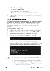
... bootable floppy disk. 4.1.2 ASUS EZ Flash utility The ASUS EZ Flash feature allows you rename the BIOS file to go through the long process of booting from a floppy disk and using EZ Flash: 1. R O M. 2. Reading file "P4GD1.ROM". To update the BIOS using a DOS-based utility. EZFlash starting BIOS update Checking for floppy... 4. A "P4GD1.ROM not found !" Press...
... bootable floppy disk. 4.1.2 ASUS EZ Flash utility The ASUS EZ Flash feature allows you rename the BIOS file to go through the long process of booting from a floppy disk and using EZ Flash: 1. R O M. 2. Reading file "P4GD1.ROM". To update the BIOS using a DOS-based utility. EZFlash starting BIOS update Checking for floppy... 4. A "P4GD1.ROM not found !" Press...


