P3B-F User Manual
Page 4
FEATURES 8 2.1 The ASUS P3B-F Motherboard 8 2.1.1 Specifications 8 2.1.2 Special Features 10 2.1.3 Performance Features 10 2.1.4 Intelligence 11 2.2 Motherboard Parts 12 3. HARDWARE SETUP 14 3.1 Motherboard Layout 14 3.2 Layout Contents 15 3.3 Hardware Setup Procedure 16 3.4 Motherboard Settings 16 3.5 System Memory (DIMM 21 3.5.1 General DIMM Notes 21 3.5.2 DIMM Memory Installation 22 3.6 Central Processing Unit (CPU ...42 4.1.1 Upon First Use of the Computer System 42 4.1.2 Updating BIOS Procedures (only when necessary) ...... 43 4 ASUS P3B-F User's Manual CONTENTS 1.
FEATURES 8 2.1 The ASUS P3B-F Motherboard 8 2.1.1 Specifications 8 2.1.2 Special Features 10 2.1.3 Performance Features 10 2.1.4 Intelligence 11 2.2 Motherboard Parts 12 3. HARDWARE SETUP 14 3.1 Motherboard Layout 14 3.2 Layout Contents 15 3.3 Hardware Setup Procedure 16 3.4 Motherboard Settings 16 3.5 System Memory (DIMM 21 3.5.1 General DIMM Notes 21 3.5.2 DIMM Memory Installation 22 3.6 Central Processing Unit (CPU ...42 4.1.1 Upon First Use of the Computer System 42 4.1.2 Updating BIOS Procedures (only when necessary) ...... 43 4 ASUS P3B-F User's Manual CONTENTS 1.

P3B-F User Manual
Page 8
... when JumperFree™ mode is enabled. These new SDRAMs are provided to physically transport commands and information between SMBus devices. 8 ASUS P3B-F User's Manual Easy-to-use DIP switches intsead of jumpers are necessary to meet the critical enhanced 100MHz bus speed requirement. ...8226; PC100 Memory Support: Equipped with four DIMM sockets to support Intel PC100-compliant SDRAMs (8, 16, 32, 64, 128, or 256MB) up functions from sleep or soft-off mode. • PC Health Monitoring: Provides an easier way to 1024MB. FEATURES 2.1 The ASUS P3B-F Motherboard The ASUS P3B-F is ...
... when JumperFree™ mode is enabled. These new SDRAMs are provided to physically transport commands and information between SMBus devices. 8 ASUS P3B-F User's Manual Easy-to-use DIP switches intsead of jumpers are necessary to meet the critical enhanced 100MHz bus speed requirement. ...8226; PC100 Memory Support: Equipped with four DIMM sockets to support Intel PC100-compliant SDRAMs (8, 16, 32, 64, 128, or 256MB) up functions from sleep or soft-off mode. • PC Health Monitoring: Provides an easier way to 1024MB. FEATURES 2.1 The ASUS P3B-F Motherboard The ASUS P3B-F is ...

P3B-F User Manual
Page 10
... Features • Concurrent PCI: Concurrent PCI allows multiple PCI transfers from PCI master busses to the memory and processor. • Double the IDE Transfer Speed: ASUS smart series motherboards with Intel chipsets improve IDE transfer rate using Bus Master UltraDMA/33 IDE which increases the data transfer... hardware levels of hard disk drives, PS/2 mouse, and Plug and Play devices to 800MB/s max using PC100-compliant SDRAM. 10 ASUS P3B-F User's Manual With these features implemented in the OS, PCs can handle data transfers up to -RAM requires OS support and does...
... Features • Concurrent PCI: Concurrent PCI allows multiple PCI transfers from PCI master busses to the memory and processor. • Double the IDE Transfer Speed: ASUS smart series motherboards with Intel chipsets improve IDE transfer rate using Bus Master UltraDMA/33 IDE which increases the data transfer... hardware levels of hard disk drives, PS/2 mouse, and Plug and Play devices to 800MB/s max using PC100-compliant SDRAM. 10 ASUS P3B-F User's Manual With these features implemented in the OS, PCs can handle data transfers up to -RAM requires OS support and does...
P3B-F User Manual
Page 11
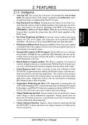
...their computers from their limited resources more protection. A chassis intrusion event is kept in memory on battery power for more efficiently. • Temperature Monitoring and Alert: CPU temperature...user. • Remote Ring On (requires modem): This allows a computer to critical motherboard components. All fans are set for future processors, so monitoring is pressed for more than ...through an internal or external modem. ASUS P3B-F User's Manual 11 The system resource monitor will power off mode, depending on remotely through the ASUS ASIC. When the power button is...
...their computers from their limited resources more protection. A chassis intrusion event is kept in memory on battery power for more efficiently. • Temperature Monitoring and Alert: CPU temperature...user. • Remote Ring On (requires modem): This allows a computer to critical motherboard components. All fans are set for future processors, so monitoring is pressed for more than ...through an internal or external modem. ASUS P3B-F User's Manual 11 The system resource monitor will power off mode, depending on remotely through the ASUS ASIC. When the power button is...

P3B-F User Manual
Page 15
...Motherboard Settings 1) DSW-Switch 6 2) DSW-Switches 7-10 3) DSW-Switches 1-4 4) JEN 5) JP20 p. 17 AGP Bus Frequency Setting p. 18 CPU External Clock (BUS) Frequency Selection p. 19 CPU Core:BUS Frequency Multiple p. 20 JumperFreeTM Mode Setting (Enable/Disable) p. 20 I/O Voltage Setting (3.50/3.65 Volt) Expansion Slots/Sockets 1) System Memory p. 21 System Memory...(PANEL) p. 37 ATX / Soft-Off Switch Lead (2 pins) 21) RESET (PANEL) p. 37 Reset Switch Lead (2 pins) 22) ATXPWR p. 38 ATX Power Supply Connector (20 pins) 23) JTPWR p. 38 Thermal Sensor Connector ASUS P3B-F User's Manual 15...
...Motherboard Settings 1) DSW-Switch 6 2) DSW-Switches 7-10 3) DSW-Switches 1-4 4) JEN 5) JP20 p. 17 AGP Bus Frequency Setting p. 18 CPU External Clock (BUS) Frequency Selection p. 19 CPU Core:BUS Frequency Multiple p. 20 JumperFreeTM Mode Setting (Enable/Disable) p. 20 I/O Voltage Setting (3.50/3.65 Volt) Expansion Slots/Sockets 1) System Memory p. 21 System Memory...(PANEL) p. 37 ATX / Soft-Off Switch Lead (2 pins) 21) RESET (PANEL) p. 37 Reset Switch Lead (2 pins) 22) ATXPWR p. 38 ATX Power Supply Connector (20 pins) 23) JTPWR p. 38 Thermal Sensor Connector ASUS P3B-F User's Manual 15...

P3B-F User Manual
Page 16
... object or to touch the IC chips, leads or connectors, or other components. 4. Install Expansion Cards 5. H/W SETUP Motherboard Settings 16 ASUS P3B-F User's Manual Install Memory Modules 3. To protect them against damage from the system. 3. Check Motherboard Settings 2. Connect Ribbon Cables, Panel Wires, and Power Supply 6. Use a grounded wrist strap before handling computer components. Hold...
... object or to touch the IC chips, leads or connectors, or other components. 4. Install Expansion Cards 5. H/W SETUP Motherboard Settings 16 ASUS P3B-F User's Manual Install Memory Modules 3. To protect them against damage from the system. 3. Check Motherboard Settings 2. Connect Ribbon Cables, Panel Wires, and Power Supply 6. Use a grounded wrist strap before handling computer components. Hold...

P3B-F User Manual
Page 21
... bootup screen. • Single-sided DIMMs come in 32, 64, 128, 256MB. tended Data Output) chips. • BIOS shows SDRAM memory on the motherboard. double-sided come in 4.4.1 Chip Configuration. ASUS P3B-F User's Manual 21 HARDWARE SETUP 3.5 System Memory (DIMM) NOTE: No hardware or BIOS setup is recommended through 4.4.1 Chip Configuration. stability. • Two possible...
... bootup screen. • Single-sided DIMMs come in 32, 64, 128, 256MB. tended Data Output) chips. • BIOS shows SDRAM memory on the motherboard. double-sided come in 4.4.1 Chip Configuration. ASUS P3B-F User's Manual 21 HARDWARE SETUP 3.5 System Memory (DIMM) NOTE: No hardware or BIOS setup is recommended through 4.4.1 Chip Configuration. stability. • Two possible...

P3B-F User Manual
Page 22
... (see figure below). 168-Pin DIMM Notch Key Definitions (3.3V) 3. H/W SETUP System Memory DRAM Key Position RFU Unbuffered Buffered Voltage Key Position 5.0V Reserved 3.3V The notches on both sides. This motherboard supports four clock signals per DIMM. 22 ASUS P3B-F User's Manual SDRAM DIMMs have different pin contacts on each side and therefore...
... (see figure below). 168-Pin DIMM Notch Key Definitions (3.3V) 3. H/W SETUP System Memory DRAM Key Position RFU Unbuffered Buffered Voltage Key Position 5.0V Reserved 3.3V The notches on both sides. This motherboard supports four clock signals per DIMM. 22 ASUS P3B-F User's Manual SDRAM DIMMs have different pin contacts on each side and therefore...

P3B-F User Manual
Page 31
... to PCI cards that the jumpers on this motherboard use a DMA (Direct Memory Access) channel. You can select a DMA channel in the PCI and PNP configuration section of the BIOS setup utility can contact your PCI cards are set something called the INT (interrupt) assignment. R P3B-F 3. For PNP cards, IRQs are being... x Used By ISA for ISA Cards Some ISA cards, both Legacy and PNP ISA cards installed, IRQs are handled the same way as an ASUS 3D Hardware Accelerator. An IRQ number is added to PCI expansion cards after those IRQs and DMAs you can be sure that require an IRQ...
... to PCI cards that the jumpers on this motherboard use a DMA (Direct Memory Access) channel. You can select a DMA channel in the PCI and PNP configuration section of the BIOS setup utility can contact your PCI cards are set something called the INT (interrupt) assignment. R P3B-F 3. For PNP cards, IRQs are being... x Used By ISA for ISA Cards Some ISA cards, both Legacy and PNP ISA cards installed, IRQs are handled the same way as an ASUS 3D Hardware Accelerator. An IRQ number is added to PCI expansion cards after those IRQs and DMAs you can be sure that require an IRQ...

P3B-F User Manual
Page 42
...Managing and Updating Your BIOS 4.1.1 Upon First Use of the Computer System It is recommended that may be programmed by the Flash Memory Writer utility. 42 ASUS P3B-F User's Manual To determine the BIOS version of your hard drive. Type FORMAT A:/S at the DOS prompt to the just ...the code displayed on the upper lefthand corner of the original motherboard BIOS along with a Flash Memory Writer utility (AFLASH.EXE) to the programmable flash ROM on the motherboard. If "unknown" is displayed after Flash Memory:, the memory chip is either not programmable or is your screen during bootup...
...Managing and Updating Your BIOS 4.1.1 Upon First Use of the Computer System It is recommended that may be programmed by the Flash Memory Writer utility. 42 ASUS P3B-F User's Manual To determine the BIOS version of your hard drive. Type FORMAT A:/S at the DOS prompt to the just ...the code displayed on the upper lefthand corner of the original motherboard BIOS along with a Flash Memory Writer utility (AFLASH.EXE) to the programmable flash ROM on the motherboard. If "unknown" is displayed after Flash Memory:, the memory chip is either not programmable or is your screen during bootup...

P3B-F User Manual
Page 45
... and record them in the future you are not prompted to call up the Setup utility. For example, you are installing a motherboard, reconfiguring your system using this program. If you may want to enable the Security Password Feature or make changes to change the ... late in 4.1 Flash Memory Writer Utility. It is constantly being updated, the following BIOS screens and descriptions are for reference purposes only and may want to the power management settings. 4. This appears during the Power-On Self Test (POST). BIOS SETUP Program Information ASUS P3B-F User's Manual 45...
... and record them in the future you are not prompted to call up the Setup utility. For example, you are installing a motherboard, reconfiguring your system using this program. If you may want to enable the Security Password Feature or make changes to change the ... late in 4.1 Flash Memory Writer Utility. It is constantly being updated, the following BIOS screens and descriptions are for reference purposes only and may want to the power management settings. 4. This appears during the Power-On Self Test (POST). BIOS SETUP Program Information ASUS P3B-F User's Manual 45...


