P2E-N User Manual
Page 4
INSTALLATION 12 ASUS P2L-N/P2E-N Motherboard Layout 12 Installation Steps 14 1. Expansion Cards 22 Expansion Card Installation Procedure 22 Assigning IRQs for Expansion Cards 22 Assigning DMA Channels for ISA ... 11 Riser Card Back 11 Riser Card Front 11 III. External Connectors 24 Front Panel Descriptions 29 Power Connection Procedures 33 IV. FEATURES 8 Features of the ASUS P2L-N/P2E-N Motherboard 8 Parts of Chipset Features Setup 44 4 ASUS P2L-N/P2E-N User's Manual Jumpers 14 2. Central Processing Unit (CPU 17 Pentium II Processor 17 AAVID Heatsink 21...
INSTALLATION 12 ASUS P2L-N/P2E-N Motherboard Layout 12 Installation Steps 14 1. Expansion Cards 22 Expansion Card Installation Procedure 22 Assigning IRQs for Expansion Cards 22 Assigning DMA Channels for ISA ... 11 Riser Card Back 11 Riser Card Front 11 III. External Connectors 24 Front Panel Descriptions 29 Power Connection Procedures 33 IV. FEATURES 8 Features of the ASUS P2L-N/P2E-N Motherboard 8 Parts of Chipset Features Setup 44 4 ASUS P2L-N/P2E-N User's Manual Jumpers 14 2. Central Processing Unit (CPU 17 Pentium II Processor 17 AAVID Heatsink 21...
P2E-N User Manual
Page 5
Audio Software 109 F. CONTENTS Power Management Setup 47 Details of Power Management Setup 47 PNP and PCI Setup 50 Details of PNP and PCI Setup 50 Load BIOS Defaults 52 Load Setup Defaults 52 Supervisor Password and User Password 53 IDE HDD Auto Detection 54 Save & Exit Setup 55 Exit Without Saving 55 V. Support CD 56 Support CD Main Menu 56 A. Video Player 97 D. Audio Driver 103 E. PC Probe Utility 57 B. ASUS LAN Card (Optional 119 ASUS P2L-N/P2E-N User's Manual 5 Video Driver (Windows 95 63 Other Video Drivers 83 C.
Audio Software 109 F. CONTENTS Power Management Setup 47 Details of Power Management Setup 47 PNP and PCI Setup 50 Details of PNP and PCI Setup 50 Load BIOS Defaults 52 Load Setup Defaults 52 Supervisor Password and User Password 53 IDE HDD Auto Detection 54 Save & Exit Setup 55 Exit Without Saving 55 V. Support CD 56 Support CD Main Menu 56 A. Video Player 97 D. Audio Driver 103 E. PC Probe Utility 57 B. ASUS LAN Card (Optional 119 ASUS P2L-N/P2E-N User's Manual 5 Video Driver (Windows 95 63 Other Video Drivers 83 C.
P2E-N User Manual
Page 7
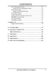
...up the BIOS software Information on -LAN 10/100 Ethernet Card (optional) ASUS P2L-N/P2E-N User's Manual 7 Features: III. Introduction: II. If you discover damaged or missing items, please contact your retailer. (1) ASUS motherboard (1) Retention mechanism & heatsink support (2) Attach mount bridges (preinstalled)... Manual (1) System housing User's Manual (1) NLX Form-factor system housing, riser card, and power supply DIMM memory module 3.5inch Floppy Drive Slim CD-ROM ASUS PCI-L101 Wake-on the included support software Item Checklist Please check that your package is divided...
...up the BIOS software Information on -LAN 10/100 Ethernet Card (optional) ASUS P2L-N/P2E-N User's Manual 7 Features: III. Introduction: II. If you discover damaged or missing items, please contact your retailer. (1) ASUS motherboard (1) Retention mechanism & heatsink support (2) Attach mount bridges (preinstalled)... Manual (1) System housing User's Manual (1) NLX Form-factor system housing, riser card, and power supply DIMM memory module 3.5inch Floppy Drive Slim CD-ROM ASUS PCI-L101 Wake-on the included support software Item Checklist Please check that your package is divided...
P2E-N User Manual
Page 8
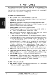
... drives. The P2L-N Motherboard adds: • Data Integrity: Features Error Checking and Correction (ECC) through the 440LX chipset and ECC supported DIMM. 8 ASUS P2L-N/P2E-N User's Manual Supports Japanese "Floppy 3 mode" (3.5inch disk drive: 1.2MB) and LS-120 floppy disk drives (3.5-inch disk drive: 120 MB,...Audio: Features ESS 16-bit audio onboard. • Versatile Memory: Supports two DIMM sockets to 256MB. • Riser Card: Provides NLX power, primary IDE, floppy drive, LAN wake up to support 8MB-128MB 168- FEATURES Features of either 512KB, 256KB, or 0KB Pipelined Burst Level...
... drives. The P2L-N Motherboard adds: • Data Integrity: Features Error Checking and Correction (ECC) through the 440LX chipset and ECC supported DIMM. 8 ASUS P2L-N/P2E-N User's Manual Supports Japanese "Floppy 3 mode" (3.5inch disk drive: 1.2MB) and LS-120 floppy disk drives (3.5-inch disk drive: 120 MB,...Audio: Features ESS 16-bit audio onboard. • Versatile Memory: Supports two DIMM sockets to 256MB. • Riser Card: Provides NLX power, primary IDE, floppy drive, LAN wake up to support 8MB-128MB 168- FEATURES Features of either 512KB, 256KB, or 0KB Pipelined Burst Level...
P2E-N User Manual
Page 9
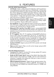
...Synchronous Dynamic Random Access Memory (SDRAM), which can imporve data transfers up to 528MB/s max (using EDO memory) to 33MB/s. ASUS P2L-N/P2E-N Performance • Concurrent PCI: Supports concurrent PCI, allowing multiple PCI transfers from PCI master buses to memory to CPU. ... 264MB/s max (using SDRAM). The best of motherboards. ASUS P2L-N/P2E-N User's Manual 9 FEATURES ASUS P2L-N/P2E-N Special Features: • ACPI Ready: Features ACPI (Advanced Configuration and Power Interface) is also implemented on all ASUS smart series of all is that supports autodetection of hard ...
...Synchronous Dynamic Random Access Memory (SDRAM), which can imporve data transfers up to 528MB/s max (using EDO memory) to 33MB/s. ASUS P2L-N/P2E-N Performance • Concurrent PCI: Supports concurrent PCI, allowing multiple PCI transfers from PCI master buses to memory to CPU. ... 264MB/s max (using SDRAM). The best of motherboards. ASUS P2L-N/P2E-N User's Manual 9 FEATURES ASUS P2L-N/P2E-N Special Features: • ACPI Ready: Features ACPI (Advanced Configuration and Power Interface) is also implemented on all ASUS smart series of all is that supports autodetection of hard ...
P2E-N User Manual
Page 10
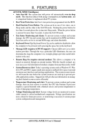
...to ensure proper system configuration and management. 10 ASUS P2L-N/P2E-N User's Manual A simple glimpse provides useful information to the user. • Remote Ring On (requires external modem): This allows a computer to be powered on by pressing the space bar on remotely ...Virus Protection: Anti-boot virus protection programmed into Sleep mode. Suggestions will power off automatically even in the world! • System Resources Alert: Today's operating systems such as information providers. FEATURES ASUS P2L-N/P2E-N Intelligence • Auto Fan Off: The system fans will give ...
...to ensure proper system configuration and management. 10 ASUS P2L-N/P2E-N User's Manual A simple glimpse provides useful information to the user. • Remote Ring On (requires external modem): This allows a computer to be powered on by pressing the space bar on remotely ...Virus Protection: Anti-boot virus protection programmed into Sleep mode. Suggestions will power off automatically even in the world! • System Resources Alert: Today's operating systems such as information providers. FEATURES ASUS P2L-N/P2E-N Intelligence • Auto Fan Off: The system fans will give ...

P2E-N User Manual
Page 11
FEATURES Parts of the ASUS P2L-N/P2E-N Motherboard T: Parallel Conn. FEATURES Motherboard Parts T: PS/2 Mouse B: PS/2 Keyboard Intel 440LX or 440EX AGPset Onboard ESS Audio 2 DIMM Sockets SEC CPU Socket (for Pentium II) Intel PIIX4 PCIset ASUS ASIC Keyboard BIOS, Multi-I/O Onboard VGA memory (SGRAM or SDRAM... PCI Slots 1 ISA Slot NLX Slot Riser Card Back IrDA Port 2 USB Ports Riser Card Front Floppy Drive Connector Primary IDE Connector NLX Power Connector ASUS P2L-N/P2E-N User's Manual 11 TV Out S-Video TV Out RCA VGA COM 1 B: Serial Conn. II. COM 2 Conn.(optional) Conn.(optional)...
FEATURES Parts of the ASUS P2L-N/P2E-N Motherboard T: Parallel Conn. FEATURES Motherboard Parts T: PS/2 Mouse B: PS/2 Keyboard Intel 440LX or 440EX AGPset Onboard ESS Audio 2 DIMM Sockets SEC CPU Socket (for Pentium II) Intel PIIX4 PCIset ASUS ASIC Keyboard BIOS, Multi-I/O Onboard VGA memory (SGRAM or SDRAM... PCI Slots 1 ISA Slot NLX Slot Riser Card Back IrDA Port 2 USB Ports Riser Card Front Floppy Drive Connector Primary IDE Connector NLX Power Connector ASUS P2L-N/P2E-N User's Manual 11 TV Out S-Video TV Out RCA VGA COM 1 B: Serial Conn. II. COM 2 Conn.(optional) Conn.(optional)...
P2E-N User Manual
Page 12
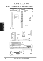
... on model) 0/1/2MB SGRAM (depending on model) ATI 3D Rage Pro AGP 2X VGA Chipset Impac TV2 1 AMC CMOS Power CR2032 3 Volt Cell Keyboard BIOS, RTC, & Multi-I/O ASUS ASIC Flash EEPROM (Programmable BIOS) Hardware Monitor PCI Slot 2 PCI Slot 1 ISA Slot 1 LAN LED Wake on LAN ...Riser Slot MIC Con. Riser Card Front Riser Slot Riser Slot Floppy Drive Conn. Infrared USB1&2 Riser Card Back Primary IDE NLX Power ASUS P2L-N/P2E-N User's Manual INSTALLATION ASUS P2L-N/P2E-N Motherboard Layout COM 1 Parallel COM 2 PS/2 RJ-45 Port RCA VGA MOUSE (TOP PORT) KEYBOARD (BOTTOM) Jack Connector ...
... on model) 0/1/2MB SGRAM (depending on model) ATI 3D Rage Pro AGP 2X VGA Chipset Impac TV2 1 AMC CMOS Power CR2032 3 Volt Cell Keyboard BIOS, RTC, & Multi-I/O ASUS ASIC Flash EEPROM (Programmable BIOS) Hardware Monitor PCI Slot 2 PCI Slot 1 ISA Slot 1 LAN LED Wake on LAN ...Riser Slot MIC Con. Riser Card Front Riser Slot Riser Slot Floppy Drive Conn. Infrared USB1&2 Riser Card Back Primary IDE NLX Power ASUS P2L-N/P2E-N User's Manual INSTALLATION ASUS P2L-N/P2E-N Motherboard Layout COM 1 Parallel COM 2 PS/2 RJ-45 Port RCA VGA MOUSE (TOP PORT) KEYBOARD (BOTTOM) Jack Connector ...
P2E-N User Manual
Page 13
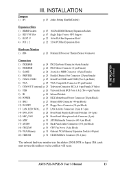
...& 4-pin Female S-Video) 8) USB p. 26 Universal Serial BUS Ports 1 & 2 (Two 4-pin Female) 9) IR p. 26 Infrared Module 10) POWER p. 26 NLX Motherboard Power Connector (20-pin Block) 11) IDE1 p. 27 Primary IDE Connector (40-pin Block) 12) FLOPPY p. 27 Floppy Drive Connector (34-pin Block) 13.... INSTALLATION Map of Board Jumpers 1) JP1 III. ASUS P2L-N/P2E-N User's Manual 13 LAN_LED, WOL_ p. 27 LAN Activity Connectors (2-pin...
...& 4-pin Female S-Video) 8) USB p. 26 Universal Serial BUS Ports 1 & 2 (Two 4-pin Female) 9) IR p. 26 Infrared Module 10) POWER p. 26 NLX Motherboard Power Connector (20-pin Block) 11) IDE1 p. 27 Primary IDE Connector (40-pin Block) 12) FLOPPY p. 27 Floppy Drive Connector (34-pin Block) 13.... INSTALLATION Map of Board Jumpers 1) JP1 III. ASUS P2L-N/P2E-N User's Manual 13 LAN_LED, WOL_ p. 27 LAN Activity Connectors (2-pin...
P2E-N User Manual
Page 14
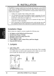
... the system. Install Expansion Cards 5. Setup the BIOS Software 1. JP1 3 2 1 Audio Enable JP1 3 2 1 Audio Disable R P2L-N/P2E-N Onboard Audio Setting 14 ASUS P2L-N/P2E-N User's Manual Set Jumpers on the inside. 2. Connect Ribbon Cables, Cabinet Wires, and Power Supply 6. Jumpers 1. Install the Central Processing Unit (CPU) 4. This is normally set to enable unless you...
... the system. Install Expansion Cards 5. Setup the BIOS Software 1. JP1 3 2 1 Audio Enable JP1 3 2 1 Audio Disable R P2L-N/P2E-N Onboard Audio Setting 14 ASUS P2L-N/P2E-N User's Manual Set Jumpers on the inside. 2. Connect Ribbon Cables, Cabinet Wires, and Power Supply 6. Jumpers 1. Install the Central Processing Unit (CPU) 4. This is normally set to enable unless you...
P2E-N User Manual
Page 15
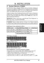
...To utilize the chipset's Error Checking and Correction (ECC) feature, you must have 18 chips or less. Memory modules with this motherboard. ASUS P2L-N/P2E-N User's Manual 15 INSTALLATION 2. System Memory (DIMM) Only Dual Inline Memory Modules (DIMM) can be used with more that 18 chips ... BIOS Chipset Setup of the BIOS SOFTWARE. INSTALLATION System Memory Non-ECC SDRAM DIMM (8 chips) General DIMM Notes: (not true for 3.3Volt (power level) Unbuffered Synchronous DRAMs (SDRAM) or EDO DRAM of the DIMM module takes up one Row on the P2L-N motherboard.) IMPORTANT: Memory speed ...
...To utilize the chipset's Error Checking and Correction (ECC) feature, you must have 18 chips or less. Memory modules with this motherboard. ASUS P2L-N/P2E-N User's Manual 15 INSTALLATION 2. System Memory (DIMM) Only Dual Inline Memory Modules (DIMM) can be used with more that 18 chips ... BIOS Chipset Setup of the BIOS SOFTWARE. INSTALLATION System Memory Non-ECC SDRAM DIMM (8 chips) General DIMM Notes: (not true for 3.3Volt (power level) Unbuffered Synchronous DRAMs (SDRAM) or EDO DRAM of the DIMM module takes up one Row on the P2L-N motherboard.) IMPORTANT: Memory speed ...
P2E-N User Manual
Page 22
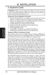
... legacy ISA cards, requires that no two devices use , leaving 6 IRQs free for your power supply when adding or removing expansion cards or other system components. Make sure that you use at the same time. 22 ASUS P2L-N/P2E-N User's Manual Expansion Card Installation Procedure 1. The original ISA expansion card design, now referred...
... legacy ISA cards, requires that no two devices use , leaving 6 IRQs free for your power supply when adding or removing expansion cards or other system components. Make sure that you use at the same time. 22 ASUS P2L-N/P2E-N User's Manual Expansion Card Installation Procedure 1. The original ISA expansion card design, now referred...

P2E-N User Manual
Page 24
... to the PS/2 mouse if one is the side closest to mini DIN adapter on the motherboard. Joystick/Midi (15-pin Female) 24 ASUS P2L-N/P2E-N User's Manual PS/2 Keyboard Connector (6 pin Female) This connector is for a standard joystick or MIDI device. If not detected, expansion ...cards can use a DIN to the power connector on the Pin 1 side of the BIOS SOFTWARE. IMPORTANT: Ribbon cables should always be less than 18in. ...
... to the PS/2 mouse if one is the side closest to mini DIN adapter on the motherboard. Joystick/Midi (15-pin Female) 24 ASUS P2L-N/P2E-N User's Manual PS/2 Keyboard Connector (6 pin Female) This connector is for a standard joystick or MIDI device. If not detected, expansion ...cards can use a DIN to the power connector on the Pin 1 side of the BIOS SOFTWARE. IMPORTANT: Ribbon cables should always be less than 18in. ...

P2E-N User Manual
Page 26
...Two 4 pin Female Sockets) Two USB ports are aligned. Find the proper orientation and push down firmly making sure that the NLX power supply can deliver at least 720mAmp on your system without this specification. IrDA / Fast IR-Compliant Infrared Module This is an onboard ...Ground -12.0 Volts +3.3 Volts +12.0 Volts +5V Standby Power OK Ground 5.0 Volts Ground +5.0 Volts Ground +3.3 Volts +3.3 Volts NLX Power Connector 26 ASUS P2L-N/P2E-N User's Manual The plug from the power supply will only insert in powering on the 5volt standby lead (5VSB). You may experience difficulty ...
...Two 4 pin Female Sockets) Two USB ports are aligned. Find the proper orientation and push down firmly making sure that the NLX power supply can deliver at least 720mAmp on your system without this specification. IrDA / Fast IR-Compliant Infrared Module This is an onboard ...Ground -12.0 Volts +3.3 Volts +12.0 Volts +5V Standby Power OK Ground 5.0 Volts Ground +5.0 Volts Ground +3.3 Volts +3.3 Volts NLX Power Connector 26 ASUS P2L-N/P2E-N User's Manual The plug from the power supply will only insert in powering on the 5volt standby lead (5VSB). You may experience difficulty ...

P2E-N User Manual
Page 27
...front panel LED to be installed. LAN activity LED Riser Card Front LAN Activity Connectors Riser Slot Wake on the IDE ribbon cable to power up when there is a wakeup package (signal) received from the network. After connecting one end to the riser card, connect the other...supports the provided floppy drive ribbon cable. IDE (Hard Disk Drive) Connector Primary IDE Connector Pin 1 Orient the red stripe on LAN activity ASUS P2L-N/P2E-N User's Manual 27 Riser Card Front Floppy Disk Drive Connector Floppy Drive Conn. LAN Activity Connectors (2 pin LAN_LED & 3 pin WOL_CON) These...
...front panel LED to be installed. LAN activity LED Riser Card Front LAN Activity Connectors Riser Slot Wake on the IDE ribbon cable to power up when there is a wakeup package (signal) received from the network. After connecting one end to the riser card, connect the other...supports the provided floppy drive ribbon cable. IDE (Hard Disk Drive) Connector Primary IDE Connector Pin 1 Orient the red stripe on LAN activity ASUS P2L-N/P2E-N User's Manual 27 Riser Card Front Floppy Disk Drive Connector Floppy Drive Conn. LAN Activity Connectors (2 pin LAN_LED & 3 pin WOL_CON) These...
P2E-N User Manual
Page 29
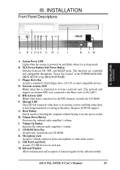
... LED Blinks when data is data being transfered or waiting in the inbox. G. The functions are controlled and configurable through the "Power Up Control" in sleep mode. Message LED The LED will remain lit when there is no modem activity and blink when there is... SETUP of infrared signals by the onboard module. USB Port1 and Port2 Accepts 15 USB devices on and blinks when it is powered on each port. ASUS P2L-N/P2E-N User's Manual 29 Requires ACPI OS support. J. D. K. Floppy Drive Bay Accepts a standard 3.5inch floppy drive, LS-120, or other audio source. L....
... LED Blinks when data is data being transfered or waiting in the inbox. G. The functions are controlled and configurable through the "Power Up Control" in sleep mode. Message LED The LED will remain lit when there is no modem activity and blink when there is... SETUP of infrared signals by the onboard module. USB Port1 and Port2 Accepts 15 USB devices on and blinks when it is powered on each port. ASUS P2L-N/P2E-N User's Manual 29 Requires ACPI OS support. J. D. K. Floppy Drive Bay Accepts a standard 3.5inch floppy drive, LS-120, or other audio source. L....

P2E-N User Manual
Page 30
... ATI video accessories such as video capture cards or television tuners. R CPU Fan Power (NC) +12 Volt Ground P2L-N/P2E-N 12Volt Cooling Fan Power 30 ASUS P2L-N/P2E-N User's Manual INSTALLATION Connectors 2 40 1 39 P2L-N/P2E-N ATI Multimedia Connector 17. Motherboard Audio Conn. 2 10 1 9 Back Panel ...ATI Multimedia Connector (40-3 pin AMC) This connector is used for audio input and output signals. Back Panel Audio Jacks P2L-N/P2E-N Audio Jack Connector Speaker Out Line Out Line In 18. III. INSTALLATION 16. Audio Connectors (Three 1/8inch. R A ribbon cable...
... ATI video accessories such as video capture cards or television tuners. R CPU Fan Power (NC) +12 Volt Ground P2L-N/P2E-N 12Volt Cooling Fan Power 30 ASUS P2L-N/P2E-N User's Manual INSTALLATION Connectors 2 40 1 39 P2L-N/P2E-N ATI Multimedia Connector 17. Motherboard Audio Conn. 2 10 1 9 Back Panel ...ATI Multimedia Connector (40-3 pin AMC) This connector is used for audio input and output signals. Back Panel Audio Jacks P2L-N/P2E-N Audio Jack Connector Speaker Out Line Out Line In 18. III. INSTALLATION 16. Audio Connectors (Three 1/8inch. R A ribbon cable...

P2E-N User Manual
Page 33
... or call your computer: You must first exit or shut down . ASUS P2L-N/P2E-N User's Manual 33 Connect the power cord into the power supply located on test. Your system power. For ATX power supplies, you turn on the power, the system may then turn off the power switch. External SCSI devices (starting with a surge protector. 5. The monitor...
... or call your computer: You must first exit or shut down . ASUS P2L-N/P2E-N User's Manual 33 Connect the power cord into the power supply located on test. Your system power. For ATX power supplies, you turn on the power, the system may then turn off the power switch. External SCSI devices (starting with a surge protector. 5. The monitor...

P2E-N User Manual
Page 37
All computer motherboards provide a Setup utility program for future reference; The BIOS ROM of product release. This appears during the Power-On Self Test (POST). BIOS SOFTWARE 6. BIOS Setup The motherboard supports two programmable Flash ROM chips: 5 Volt and 12 Volt. in a ... You can be slightly different. But do so only if the first two methods fail. Your BIOS version may have already been made. ASUS P2L-N/P2E-N User's Manual 37 Press to enter new setup information. If your system using this program. This section describes how to run this utility...
All computer motherboards provide a Setup utility program for future reference; The BIOS ROM of product release. This appears during the Power-On Self Test (POST). BIOS SOFTWARE 6. BIOS Setup The motherboard supports two programmable Flash ROM chips: 5 Volt and 12 Volt. in a ... You can be slightly different. But do so only if the first two methods fail. Your BIOS version may have already been made. ASUS P2L-N/P2E-N User's Manual 37 Press to enter new setup information. If your system using this program. This section describes how to run this utility...
P2E-N User Manual
Page 38
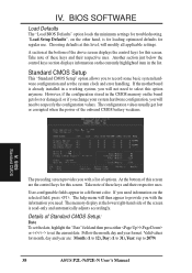
... use. A section at this screen. If you will not need . "Load Setup Defaults", on the board gets lost or corrupted when the power of options. Standard CMOS Setup This "Standard CMOS Setup" option allows you with a list of the onboard CMOS battery weakens. However, if the... configuration stored in the CMOS memory on the other hand, is already installed in a working system, you need to 2079) 38 ASUS P2L-N/P2E-N User's Manual At the bottom of these keys and their respective uses. BIOS Standard CMOS The preceding screen provides you with the information...
... use. A section at this screen. If you will not need . "Load Setup Defaults", on the board gets lost or corrupted when the power of options. Standard CMOS Setup This "Standard CMOS Setup" option allows you with a list of the onboard CMOS battery weakens. However, if the... configuration stored in the CMOS memory on the other hand, is already installed in a working system, you need to 2079) 38 ASUS P2L-N/P2E-N User's Manual At the bottom of these keys and their respective uses. BIOS Standard CMOS The preceding screen provides you with the information...


