
P2B User Manual
Page 3
... +1-510-608-4555 Email: info-usa@asus.com.tw Technical Support Fax: +1-510-608-4555 BBS: +1-510-739-3774 Email: tsd-usa@asus.com.tw WWW: www.asus.com FTP: ftp.asus.com.tw/pub/ASUS ASUS COMPUTER GmbH (Europe) Marketing Address: Harkort ...Str. 25, 40880 Ratingen, BRD, Germany Telephone: 49-2102-445011 Fax: 49-2102-442066 Email: [email protected] Technical Support Hotline: 49-2102-499712 BBS: 49-2102-448690 Email: [email protected] WWW: www.asuscom.de FTP: ftp.asuscom.de/pub/ASUSCOM ASUS P2B...
... +1-510-608-4555 Email: info-usa@asus.com.tw Technical Support Fax: +1-510-608-4555 BBS: +1-510-739-3774 Email: tsd-usa@asus.com.tw WWW: www.asus.com FTP: ftp.asus.com.tw/pub/ASUS ASUS COMPUTER GmbH (Europe) Marketing Address: Harkort ...Str. 25, 40880 Ratingen, BRD, Germany Telephone: 49-2102-445011 Fax: 49-2102-442066 Email: [email protected] Technical Support Hotline: 49-2102-499712 BBS: 49-2102-448690 Email: [email protected] WWW: www.asuscom.de FTP: ftp.asuscom.de/pub/ASUSCOM ASUS P2B...

P2B User Manual
Page 4
... of the ASUS P2B Motherboard 10 Installation Steps 12 Jumpers 12 Jumper Settings 13 System Memory (DIMM 17 SPD Support 17 DIMM Memory Installation Procedures 18 Central Processing Unit (CPU 19 Universal Retention Mechanism 19 Heatsinks 19 Installing the Processor 20 ASUS Smart Thermal ... Monitor 25 External Connectors 26 Power Connection Procedures 33 Power Connection Procedures 33 4 ASUS P2B User's Manual HARDWARE SETUP 10 Layout of the ASUS P2B Motherboard 8 The ASUS P2B Motherboard 9 III. CONTENTS I. INTRODUCTION 7 How this Manual is Organized 7 Item Checklist 7 II...
... of the ASUS P2B Motherboard 10 Installation Steps 12 Jumpers 12 Jumper Settings 13 System Memory (DIMM 17 SPD Support 17 DIMM Memory Installation Procedures 18 Central Processing Unit (CPU 19 Universal Retention Mechanism 19 Heatsinks 19 Installing the Processor 20 ASUS Smart Thermal ... Monitor 25 External Connectors 26 Power Connection Procedures 33 Power Connection Procedures 33 4 ASUS P2B User's Manual HARDWARE SETUP 10 Layout of the ASUS P2B Motherboard 8 The ASUS P2B Motherboard 9 III. CONTENTS I. INTRODUCTION 7 How this Manual is Organized 7 Item Checklist 7 II...

P2B User Manual
Page 5
CONTENTS IV. SUPPORT SOFTWARE 56 Desktop Management Interface (DMI 56 Introducing the ASUS DMI Configuration Utility 56 System Requirements 56 Using the ASUS DMI Configuration Utility 57 VI. BIOS SETUP 34 Managing and Updating Your BIOS 34 Upon First Use of the Computer System 34 Updating ... 52 Supervisor Password and User Password 53 IDE HDD Auto Detection 54 Save & Exit Setup 55 Exit Without Saving 55 V. APPENDIX 59 The ASUS CIDB Chassis Intrusion Sensor Module 59 The ASUS S370 CPU Card 61 ASUS PCI-L101 Fast Ethernet Card 63 Glossary 65 ASUS P2B User's Manual 5
CONTENTS IV. SUPPORT SOFTWARE 56 Desktop Management Interface (DMI 56 Introducing the ASUS DMI Configuration Utility 56 System Requirements 56 Using the ASUS DMI Configuration Utility 57 VI. BIOS SETUP 34 Managing and Updating Your BIOS 34 Upon First Use of the Computer System 34 Updating ... 52 Supervisor Password and User Password 53 IDE HDD Auto Detection 54 Save & Exit Setup 55 Exit Without Saving 55 V. APPENDIX 59 The ASUS CIDB Chassis Intrusion Sensor Module 59 The ASUS S370 CPU Card 61 ASUS PCI-L101 Fast Ethernet Card 63 Glossary 65 ASUS P2B User's Manual 5

P2B User Manual
Page 7
... on setting up the BIOS software V. Appendix Optional items and general reference Item Checklist Please check that your retailer. (1) ASUS Motherboard (1) Universal Retention Mechanism for SECC/SECC2/SEPP (1) IDE ribbon cable for master and slave drives (1) Floppy ribbon cable... caps (1) Support CD with drivers and utilities (1) User's manual S-P2FAN or P2T-Cable for Slot 1 processors IrDA-compliant infrared module (optional) ASUS PCI-L101 Wake-on the included support software VI. I . Support Software: Information on -LAN 10/100 Ethernet Card (optional) ASUS P2B User's Manual...
... on setting up the BIOS software V. Appendix Optional items and general reference Item Checklist Please check that your retailer. (1) ASUS Motherboard (1) Universal Retention Mechanism for SECC/SECC2/SEPP (1) IDE ribbon cable for master and slave drives (1) Floppy ribbon cable... caps (1) Support CD with drivers and utilities (1) User's manual S-P2FAN or P2T-Cable for Slot 1 processors IrDA-compliant infrared module (optional) ASUS PCI-L101 Wake-on the included support software VI. I . Support Software: Information on -LAN 10/100 Ethernet Card (optional) ASUS P2B User's Manual...

P2B User Manual
Page 8
...Windows 98 compatibility, built-in a Single Edge Processor Package (SEPP). • SCSI BIOS: Supports optional ASUS SCSI cards through onboard SYMBIOS firmware. • IrDA: Supports an optional infrared port module for wireless interface. • Concurrent PCI: Allows multiple PCI ...; Universal Retention Mechanism: Supports a Pentium® II processor packaged in a Single Edge Contact Cartridge (SECC/SECC2) or a CeleronTM processor packaged in hardware-based virus protection through Trend ChipAway Virus, and autodetection of the ASUS P2B Motherboard The ASUS P2B is used to 768MB....
...Windows 98 compatibility, built-in a Single Edge Processor Package (SEPP). • SCSI BIOS: Supports optional ASUS SCSI cards through onboard SYMBIOS firmware. • IrDA: Supports an optional infrared port module for wireless interface. • Concurrent PCI: Allows multiple PCI ...; Universal Retention Mechanism: Supports a Pentium® II processor packaged in a Single Edge Contact Cartridge (SECC/SECC2) or a CeleronTM processor packaged in hardware-based virus protection through Trend ChipAway Virus, and autodetection of the ASUS P2B Motherboard The ASUS P2B is used to 768MB....

P2B User Manual
Page 11
ASUS P2B User's Manual 11 III. HARDWARE SETUP Jumpers 1) CLRTC p. 13 Clear Real Time Clock (RTC) RAM (Short/Clear CMOS) 2) KBPWR p. 13 Keyboard Power 3) FS0, FS1, FS2 p. 14 CPU External Clock (BUS) Frequency Selection 4) BF0, BF1, BF2, BF3 p. 14 CPU Core:BUS Frequency Multiple Expansion Slots/Sockets 1) System Memory p. 17 System Memory Support... 2) DIMM Sockets p. 18 DIMM Memory Module Support 3) CPU Slot 1 p. 19 Pentium II/Celeron CPU Support 4) SLOT1, SLOT2, SLOT3 p. 24 16-bit ISA Bus ...
ASUS P2B User's Manual 11 III. HARDWARE SETUP Jumpers 1) CLRTC p. 13 Clear Real Time Clock (RTC) RAM (Short/Clear CMOS) 2) KBPWR p. 13 Keyboard Power 3) FS0, FS1, FS2 p. 14 CPU External Clock (BUS) Frequency Selection 4) BF0, BF1, BF2, BF3 p. 14 CPU Core:BUS Frequency Multiple Expansion Slots/Sockets 1) System Memory p. 17 System Memory Support... 2) DIMM Sockets p. 18 DIMM Memory Module Support 3) CPU Slot 1 p. 19 Pentium II/Celeron CPU Support 4) SLOT1, SLOT2, SLOT3 p. 24 16-bit ISA Bus ...

P2B User Manual
Page 13
III. H/W SETUP Jumpers ASUS P2B User's Manual 13 R R P2B Clear RTC RAM Short small solder points to disable or enable the keyboard...AC power, (2) Short the two points labeled CLRTC, (3) Turn on the +5VSB lead and the new ACPI BIOS support. This feature requires an ATX power supply that can supply at least 300mA on your computer. Your computer will not... Power Up (KBPWR) This allows you do not have the appropriate ATX power supply. KBPWR 123 123 Disable Enable P2B Keyboard Power Up III. Clear Real Time Clock (RTC) RAM (CLRTC) The CMOS RAM is set this to ...
III. H/W SETUP Jumpers ASUS P2B User's Manual 13 R R P2B Clear RTC RAM Short small solder points to disable or enable the keyboard...AC power, (2) Short the two points labeled CLRTC, (3) Turn on the +5VSB lead and the new ACPI BIOS support. This feature requires an ATX power supply that can supply at least 300mA on your computer. Your computer will not... Power Up (KBPWR) This allows you do not have the appropriate ATX power supply. KBPWR 123 123 Disable Enable P2B Keyboard Power Up III. Clear Real Time Clock (RTC) RAM (CLRTC) The CMOS RAM is set this to ...

P2B User Manual
Page 17
... NOTE: No hardware or BIOS setup is the memory of choice for 3.3Volt (power level) unbuffered Synchronous Dynamic Random Access Memory (SDRAM). ASUS P2B User's Manual 17 H/W SETUP System Memory III. To utilize the chipset's Error Checking and Correction (ECC) feature, you must use only PC100...-compli- General DIMM Notes • For the system CPU bus to 66MHz for system stability. • ASUS motherboards support SPD (Serial Presence Detect) DIMMs. This is required after adding or removing memory. Sockets are not PC100-compliant, set the CPU bus ...
... NOTE: No hardware or BIOS setup is the memory of choice for 3.3Volt (power level) unbuffered Synchronous Dynamic Random Access Memory (SDRAM). ASUS P2B User's Manual 17 H/W SETUP System Memory III. To utilize the chipset's Error Checking and Correction (ECC) feature, you must use only PC100...-compli- General DIMM Notes • For the system CPU bus to 66MHz for system stability. • ASUS motherboards support SPD (Serial Presence Detect) DIMMs. This is required after adding or removing memory. Sockets are not PC100-compliant, set the CPU bus ...

P2B User Manual
Page 18
DRAM SIMM modules have a higher pin density. 20 Pins 60 Pins 88 Pins Lock P2B 168-Pin DIMM Memory Sockets FRONT The DIMMs must tell your retailer the correct DIMM type before purchasing. R III. H/W SETUP System Memory III. HARDWARE SETUP ... Position RFU Unbuffered Buffered Voltage Key Position 5.0V Reserved 3.3V The notches on the DIMM will only fit in the orientation as shown. This motherboard supports four clock signals. 18 ASUS P2B User's Manual
DRAM SIMM modules have a higher pin density. 20 Pins 60 Pins 88 Pins Lock P2B 168-Pin DIMM Memory Sockets FRONT The DIMMs must tell your retailer the correct DIMM type before purchasing. R III. H/W SETUP System Memory III. HARDWARE SETUP ... Position RFU Unbuffered Buffered Voltage Key Position 5.0V Reserved 3.3V The notches on the DIMM will only fit in the orientation as shown. This motherboard supports four clock signals. 18 ASUS P2B User's Manual

P2B User Manual
Page 19
...and Celeron processors are provided for instructions on the motherboard. You may be used on any ASUS motherboard with three-pin fans that the clamping design is working. An ASUS S370 CPU card can be connected to be different from the following pictures are those with ...an SECC with heatsink and fan (top view) Pentium III (in a Single Edge Processor Package (SEPP). The URM supports Pentium III / II and Celeron processors. ASUS P2B User's Manual 19 Universal Retention Mechanism Your motherboard comes preinstalled with heatsink and fan NOTE: The SEPP fan (for a ...
...and Celeron processors are provided for instructions on the motherboard. You may be used on any ASUS motherboard with three-pin fans that the clamping design is working. An ASUS S370 CPU card can be connected to be different from the following pictures are those with ...an SECC with heatsink and fan (top view) Pentium III (in a Single Edge Processor Package (SEPP). The URM supports Pentium III / II and Celeron processors. ASUS P2B User's Manual 19 Universal Retention Mechanism Your motherboard comes preinstalled with heatsink and fan NOTE: The SEPP fan (for a ...

P2B User Manual
Page 20
... place. The following steps are locked when shipped. Place the metal clip on the ends of your processor. The URM is different. 20 ASUS P2B User's Manual Using the SECC fan with your heatsink. Four Pins and metal clip NOTE: The SEPP heatsink and fan (for your heatsink ...or processor. Unlock the URM's Folding Support Arms: The folding support arms of the SECC2. HARDWARE SETUP Installing the Processor 1. H/W SETUP CPU III. Lock Arm Lock Arm Using the SECC2 fan with ...
... place. The following steps are locked when shipped. Place the metal clip on the ends of your processor. The URM is different. 20 ASUS P2B User's Manual Using the SECC fan with your heatsink. Four Pins and metal clip NOTE: The SEPP heatsink and fan (for your heatsink ...or processor. Unlock the URM's Folding Support Arms: The folding support arms of the SECC2. HARDWARE SETUP Installing the Processor 1. H/W SETUP CPU III. Lock Arm Lock Arm Using the SECC2 fan with ...

P2B User Manual
Page 25
... an accelerated graphics port (AGP) slot to PnP cards from those used by legacy cards. R P2B Accelerated Graphics Port (AGP) ASUS P2B User's Manual 25 For PnP cards, IRQs are assigned to support a new generation of the BIOS Setup utility. In the PCI bus design, the BIOS automatically assigns... and PnP configuration section of graphics cards with the Plug and Play (PnP specification, which IRQs are handled the same way as an ASUS 3D Hardware Accelerator. IMPORTANT: To avoid conflicts, reserve the necessary IRQs and DMAs for ISA Cards Some ISA cards, both legacy and...
... an accelerated graphics port (AGP) slot to PnP cards from those used by legacy cards. R P2B Accelerated Graphics Port (AGP) ASUS P2B User's Manual 25 For PnP cards, IRQs are assigned to support a new generation of the BIOS Setup utility. In the PCI bus design, the BIOS automatically assigns... and PnP configuration section of graphics cards with the Plug and Play (PnP specification, which IRQs are handled the same way as an ASUS 3D Hardware Accelerator. IMPORTANT: To avoid conflicts, reserve the necessary IRQs and DMAs for ISA Cards Some ISA cards, both legacy and...

P2B User Manual
Page 27
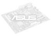
Floppy Disk Drive Connector (34-1pin FLOPPY) This connector supports the provided floppy disk drive ribbon cable. III. NOTE: Serial printers must be used for pointing devices or other end to the floppy drives. (Pin 5 ...) 4. See "Onboard Serial Port" in Chipset Features Setup of the BIOS SOFTWARE. HARDWARE SETUP 3. After connecting the single end to Pin 1 R Pin 1 Floppy Drive Connector P2B Floppy Disk Drive Connector ASUS P2B User's Manual 27
Floppy Disk Drive Connector (34-1pin FLOPPY) This connector supports the provided floppy disk drive ribbon cable. III. NOTE: Serial printers must be used for pointing devices or other end to the floppy drives. (Pin 5 ...) 4. See "Onboard Serial Port" in Chipset Features Setup of the BIOS SOFTWARE. HARDWARE SETUP 3. After connecting the single end to Pin 1 R Pin 1 Floppy Drive Connector P2B Floppy Disk Drive Connector ASUS P2B User's Manual 27
P2B User Manual
Page 28
... to the Primary or Secondary IDE connectors will cause the LED to prevent inserting in the BIOS Features Setup of your hard disk(s). BIOS now supports SCSI device or IDE CD-ROM bootup (see "HDD Sequence SCSI/IDE First" & "Boot Sequence" in the wrong orientation when using one ... Activity LED TIP: If the case-mounted LED does not light, try reversing the 2-pin plug. 28 ASUS P2B User's Manual Primary / Secondary IDE Connectors (Two 40-1pin IDE) These connectors support the provided IDE hard disk ribbon cable. TIP: You may install one ribbon cable on the primary IDE connector...
... to the Primary or Secondary IDE connectors will cause the LED to prevent inserting in the BIOS Features Setup of your hard disk(s). BIOS now supports SCSI device or IDE CD-ROM bootup (see "HDD Sequence SCSI/IDE First" & "Boot Sequence" in the wrong orientation when using one ... Activity LED TIP: If the case-mounted LED does not light, try reversing the 2-pin plug. 28 ASUS P2B User's Manual Primary / Secondary IDE Connectors (Two 40-1pin IDE) These connectors support the provided IDE hard disk ribbon cable. TIP: You may install one ribbon cable on the primary IDE connector...

P2B User Manual
Page 29
... +12V GND III. H/W SETUP Connectors III. HARDWARE SETUP 9. Chassis / CPU / Power Supply Fan Connectors (3-pin FAN) These connectors support cooling fans of the expansion slots. Orientate the fans so that the heat sink fins allow airflow to go across the CPU and onboard heatsinks... is opened or drive bay doors are opened , connect/short the Chassis Signal pin to the Ground pin. +5VSB Chassis Signal Ground P2B Chassis Intrusion Alarm Lead R R ASUS P2B User's Manual 29 Depending on the fan manufacturer, the wiring and plug may occur to be different. Power Supply Fan CPU Fan Power...
... +12V GND III. H/W SETUP Connectors III. HARDWARE SETUP 9. Chassis / CPU / Power Supply Fan Connectors (3-pin FAN) These connectors support cooling fans of the expansion slots. Orientate the fans so that the heat sink fins allow airflow to go across the CPU and onboard heatsinks... is opened or drive bay doors are opened , connect/short the Chassis Signal pin to the Ground pin. +5VSB Chassis Signal Ground P2B Chassis Intrusion Alarm Lead R R ASUS P2B User's Manual 29 Depending on the fan manufacturer, the wiring and plug may occur to be different. Power Supply Fan CPU Fan Power...

P2B User Manual
Page 30
... at least 10mAmp on system cases that the pins are aligned. Find the proper orientation and push down firmly but gently making sure that support this feature. H/W SETUP Connectors +5.0 Volts +5.0 Volts -5.0 Volts Ground Ground Ground PWR Supply On Ground -12.0Volts +3.3Volts R +12...0Volts +5V Standby Power Good Ground +5.0 Volts Ground +5.0 Volts Ground +3.3 Volts +3.3 Volts P2B ATX Power Connector IMPORTANT: Make sure that your ATX power supply can supply at least 720mA. 30 ASUS P2B User's Manual This module mounts to the motherboard 12. The plug from the module to...
... at least 10mAmp on system cases that the pins are aligned. Find the proper orientation and push down firmly but gently making sure that support this feature. H/W SETUP Connectors +5.0 Volts +5.0 Volts -5.0 Volts Ground Ground Ground PWR Supply On Ground -12.0Volts +3.3Volts R +12...0Volts +5V Standby Power Good Ground +5.0 Volts Ground +5.0 Volts Ground +3.3 Volts +3.3 Volts P2B ATX Power Connector IMPORTANT: Make sure that your ATX power supply can supply at least 720mA. 30 ASUS P2B User's Manual This module mounts to the motherboard 12. The plug from the module to...

P2B User Manual
Page 32
The LED will switch the system between ON and SLEEP. This function requires ACPI OS and driver support. 17. Pushing the button once will remain lit when there is no signal and blink when there is data transfer or waiting in the inbox. ... connects the system power LED, which lights when the system is in the ON mode for the connector, you do not have a function. P2B System Panel Connections 32 ASUS P2B User's Manual This 2-pin connector (see the figure below) connects to the case-mounted speaker. If you may use . Pushing the switch while...
The LED will switch the system between ON and SLEEP. This function requires ACPI OS and driver support. 17. Pushing the button once will remain lit when there is no signal and blink when there is data transfer or waiting in the inbox. ... connects the system power LED, which lights when the system is in the ON mode for the connector, you do not have a function. P2B System Panel Connections 32 ASUS P2B User's Manual This 2-pin connector (see the figure below) connects to the case-mounted speaker. If you may use . Pushing the switch while...
P2B User Manual
Page 34
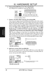
...DO NOT copy AUTOEXEC.BAT & CONFIG.SYS to create a bootable system floppy disk. Type COPY D:\AFLASH\AFLASH.EXE A:\ (assuming D is not supported by the ACPI BIOS and therefore, cannot be loaded when you boot from the floppy disk. IV. To determine the BIOS version of your ...chip is either not programmable or is your screen during bootup. It it recommended that updates the BIOS by the Flash Memory Writer utility. 34 ASUS P2B User's Manual BIOS SETUP Managing and Updating Your BIOS Upon First Use of the original motherboard BIOS along with a Flash Memory Writer utility (AFLASH...
...DO NOT copy AUTOEXEC.BAT & CONFIG.SYS to create a bootable system floppy disk. Type COPY D:\AFLASH\AFLASH.EXE A:\ (assuming D is not supported by the ACPI BIOS and therefore, cannot be loaded when you boot from the floppy disk. IV. To determine the BIOS version of your ...chip is either not programmable or is your screen during bootup. It it recommended that updates the BIOS by the Flash Memory Writer utility. 34 ASUS P2B User's Manual BIOS SETUP Managing and Updating Your BIOS Upon First Use of the original motherboard BIOS along with a Flash Memory Writer utility (AFLASH...

P2B User Manual
Page 37
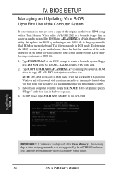
...Press to run this section. IV. If your system using this utility. This appears during the Power-On Self Test (POST). BIOS Updating BIOS ASUS P2B User's Manual 37 If so, invoke the Setup utility, as described in detail in particular, the hard disk specifications. But do so only if ...reset the system by pressing + + , or by turning the system off and then back on the system case. BIOS SETUP BIOS Setup The motherboard supports a 5 Volt programmable Flash ROM chip, which can also restart by pressing the Reset button on again. Use the Flash Memory Writer utility to enter ...
...Press to run this section. IV. If your system using this utility. This appears during the Power-On Self Test (POST). BIOS Updating BIOS ASUS P2B User's Manual 37 If so, invoke the Setup utility, as described in detail in particular, the hard disk specifications. But do so only if ...reset the system by pressing + + , or by turning the system off and then back on the system case. BIOS SETUP BIOS Setup The motherboard supports a 5 Volt programmable Flash ROM chip, which can also restart by pressing the Reset button on again. Use the Flash Memory Writer utility to enter ...
P2B User Manual
Page 39
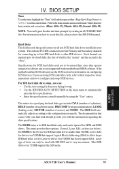
...HEAD (number of read/write heads), PRECOMP (write precompensation), LANDZ (landing zone), SECTOR (number of sectors) and MODE. BIOS Standard CMOS ASUS P2B User's Manual 39 the first of drive can bypass the date and time prompts by the motherboard BIOS software. For IDE hard disk drive ...setup, you with MS-DOS and is the "slave". The documentation that support Logical Block Addressing (LBA) to two hard disks; If the motherboard has SCSI onboard, see below). The entries for information on configuring...
...HEAD (number of read/write heads), PRECOMP (write precompensation), LANDZ (landing zone), SECTOR (number of sectors) and MODE. BIOS Standard CMOS ASUS P2B User's Manual 39 the first of drive can bypass the date and time prompts by the motherboard BIOS software. For IDE hard disk drive ...setup, you with MS-DOS and is the "slave". The documentation that support Logical Block Addressing (LBA) to two hard disks; If the motherboard has SCSI onboard, see below). The entries for information on configuring...


