P2B-N User Manual
Page 2
...USE ONLY, AND ARE SUBJECT TO CHANGE AT ANY TIME WITHOUT NOTICE, AND SHOULD NOT BE CONSTRUED AS A COMMITMENT BY ASUS. Copyright © 1999 ASUSTeK COMPUTER INC. Product Name: ASUS P2B-N Manual Revision: 1.04 E407 Release Date: July 1999 2 ASUS P2B-N User's Manual or (2) the serial number of ... • Windows and MS-DOS are registered trademarks of Microsoft Corporation. • Adobe and Acrobat are represented by ASUS; All Rights Reserved. ASUS ASSUMES NO RESPONSIBILITY OR LIABILITY FOR ANY ERRORS OR INACCURACIES THAT MAY APPEAR IN THIS MANUAL, INCLUDING THE PRODUCTS AND SOFTWARE...
...USE ONLY, AND ARE SUBJECT TO CHANGE AT ANY TIME WITHOUT NOTICE, AND SHOULD NOT BE CONSTRUED AS A COMMITMENT BY ASUS. Copyright © 1999 ASUSTeK COMPUTER INC. Product Name: ASUS P2B-N Manual Revision: 1.04 E407 Release Date: July 1999 2 ASUS P2B-N User's Manual or (2) the serial number of ... • Windows and MS-DOS are registered trademarks of Microsoft Corporation. • Adobe and Acrobat are represented by ASUS; All Rights Reserved. ASUS ASSUMES NO RESPONSIBILITY OR LIABILITY FOR ANY ERRORS OR INACCURACIES THAT MAY APPEAR IN THIS MANUAL, INCLUDING THE PRODUCTS AND SOFTWARE...
P2B-N User Manual
Page 11
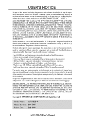
... 3D Rage Pro AGP 2X/Rage IIC VGA Chipset* CPU Slot 1 Universal Folding Retention Mechanism Intel PIIX4E PCIset Intel 440BX AGPset Slim CD-ROM Connector ASUS ASIC Keyboard BIOS, Multi-I/O Programmable Flash EEPROM H/W Monitoring ASIC* *Optional at the time of purchase ASUS P2B-N User's Manual 11 FEATURES 2.2 ASUS P2B-N Parts T: Parallel Conn.
... 3D Rage Pro AGP 2X/Rage IIC VGA Chipset* CPU Slot 1 Universal Folding Retention Mechanism Intel PIIX4E PCIset Intel 440BX AGPset Slim CD-ROM Connector ASUS ASIC Keyboard BIOS, Multi-I/O Programmable Flash EEPROM H/W Monitoring ASIC* *Optional at the time of purchase ASUS P2B-N User's Manual 11 FEATURES 2.2 ASUS P2B-N Parts T: Parallel Conn.
P2B-N User Manual
Page 12
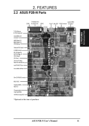
... MODEM LAN Controller LANDIS_EN VIO CPU Slot 1 ATI 3D Rage Pro AGP 2X/ Rage IIC VGA Chipset PCI Audio AUDIS_EN Intel PIIX4E Chipset ® P2B-N DIMM Socket 2 (64/72-bit, 168-pin module) DIMM Socket 1 (64/72-bit, 168-pin module) BF0 BF1 BF2 BF3 CDROM... Connector Intel 440BX AGPset 3 2 1 0 Row Keyboard BIOS, RTC, & Multi-I/O ASUS ASIC FS0 FS1 FS2 BUS FREQ SELECT CMOS Power CR2032 3 Volt Cell KB_WAKE CLR_RTC Flash EEPROM (Programmable BIOS) CHASIS_FAN (Grayed items are optional at the time of purchase.) FREQ MULT Hardware Monitor 12 ASUS P2B-N User's Manual 3.
... MODEM LAN Controller LANDIS_EN VIO CPU Slot 1 ATI 3D Rage Pro AGP 2X/ Rage IIC VGA Chipset PCI Audio AUDIS_EN Intel PIIX4E Chipset ® P2B-N DIMM Socket 2 (64/72-bit, 168-pin module) DIMM Socket 1 (64/72-bit, 168-pin module) BF0 BF1 BF2 BF3 CDROM... Connector Intel 440BX AGPset 3 2 1 0 Row Keyboard BIOS, RTC, & Multi-I/O ASUS ASIC FS0 FS1 FS2 BUS FREQ SELECT CMOS Power CR2032 3 Volt Cell KB_WAKE CLR_RTC Flash EEPROM (Programmable BIOS) CHASIS_FAN (Grayed items are optional at the time of purchase.) FREQ MULT Hardware Monitor 12 ASUS P2B-N User's Manual 3.
P2B-N User Manual
Page 14
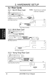
... 3.2.1 NLX-R Riser Card CHASS_DET NLX_EXT PCI2 ® NLX-R PCI1 LAN LEDWOL_CON ISA HEAD_SPK NLX_SLOT NLX-R Riser Card Front NOTE: Grayed items are optional at the time of purchase. FLOPPY MIC-CON USB FCON IR CIR IDE1 POWER NLX-R Riser Card Back 3.2.2 B9-N Riser Card CHASS_DET PCI3 ® PCI2 WAKEUP PCI1 ISA... WOL_CON IDE1 FLOPPY RISER Yeong-Yang Riser Card Front MIC USB IR Panel PWRLED HDD_LED RESET PWRSW SPKR Power Yeong-Yang Riser Card Back 14 ASUS P2B-N User's Manual 3.
... 3.2.1 NLX-R Riser Card CHASS_DET NLX_EXT PCI2 ® NLX-R PCI1 LAN LEDWOL_CON ISA HEAD_SPK NLX_SLOT NLX-R Riser Card Front NOTE: Grayed items are optional at the time of purchase. FLOPPY MIC-CON USB FCON IR CIR IDE1 POWER NLX-R Riser Card Back 3.2.2 B9-N Riser Card CHASS_DET PCI3 ® PCI2 WAKEUP PCI1 ISA... WOL_CON IDE1 FLOPPY RISER Yeong-Yang Riser Card Front MIC USB IR Panel PWRLED HDD_LED RESET PWRSW SPKR Power Yeong-Yang Riser Card Back 14 ASUS P2B-N User's Manual 3.
P2B-N User Manual
Page 23
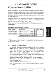
... 32, 64, 128, 256MB x1 Socket 2 (Rows 2&3) SDRAM 8, 16, 32, 64, 128, 256MB x1 Total System Memory (Max 512MB) = NOTE: At the time this User's Manual was written, 256MB DIMMs are only available as registered memory. 3.5.1 General DIMM Notes • For the system CPU bus to ensure system...System Memory (DIMM) NOTE: No hardware or BIOS setup is the memory of the strict timing issues involved under this speed. tended Data Output) chips. • BIOS shows SDRAM memory on the motherboard. ASUS P2B-N User's Manual 23 stability. • Two possible memory chips are supported: SDRAM with...
... 32, 64, 128, 256MB x1 Socket 2 (Rows 2&3) SDRAM 8, 16, 32, 64, 128, 256MB x1 Total System Memory (Max 512MB) = NOTE: At the time this User's Manual was written, 256MB DIMMs are only available as registered memory. 3.5.1 General DIMM Notes • For the system CPU bus to ensure system...System Memory (DIMM) NOTE: No hardware or BIOS setup is the memory of the strict timing issues involved under this speed. tended Data Output) chips. • BIOS shows SDRAM memory on the motherboard. ASUS P2B-N User's Manual 23 stability. • Two possible memory chips are supported: SDRAM with...
P2B-N User Manual
Page 30
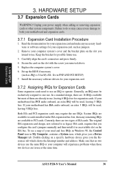
..., requires that no two devices use , leaving 6 IRQs free for Expansion Cards Some expansion cards need to one use at the same time. System IRQs are available to PCI cards. Read the documentation for your motherboard has ISA audio onboard, an extra 3 IRQs will experience ...in use the same IRQ or your used , leaving 3 IRQs free. HARDWARE SETUP 3.7 Expansion Cards WARNING! Replace the computer system's cover. 6. ASUS P2B-N User's Manual 30 Install the necessary software drivers for your expansion card and make any remaining IRQs are two types of your computer will be...
..., requires that no two devices use , leaving 6 IRQs free for Expansion Cards Some expansion cards need to one use at the same time. System IRQs are available to PCI cards. Read the documentation for your motherboard has ISA audio onboard, an extra 3 IRQs will experience ...in use the same IRQ or your used , leaving 3 IRQs free. HARDWARE SETUP 3.7 Expansion Cards WARNING! Replace the computer system's cover. 6. ASUS P2B-N User's Manual 30 Install the necessary software drivers for your expansion card and make any remaining IRQs are two types of your computer will be...
P2B-N User Manual
Page 33
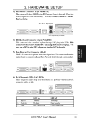
... hub. This connector allows the motherboard to connect to mini DIN adapter on 10Mbps No data Bad connection LED off 100Mbps Data transfer Good connection ASUS P2B-N User's Manual 33 This connector will direct IRQ12 to the PS/2 mouse if one is a problem with the network connector, cable, or hub. 1 Speed 2 Activity...) 3. See PS/2 Mouse Control in 4.4 BIOS Features Setup. H/W SETUP Connectors PS/2 Keyboard (6-pin female) 4) PS/2 Keyboard Connector (6-pin PS2KBMS) This connector is optional at the time of purchase. You may use IRQ12.
... hub. This connector allows the motherboard to connect to mini DIN adapter on 10Mbps No data Bad connection LED off 100Mbps Data transfer Good connection ASUS P2B-N User's Manual 33 This connector will direct IRQ12 to the PS/2 mouse if one is a problem with the network connector, cable, or hub. 1 Speed 2 Activity...) 3. See PS/2 Mouse Control in 4.4 BIOS Features Setup. H/W SETUP Connectors PS/2 Keyboard (6-pin female) 4) PS/2 Keyboard Connector (6-pin PS2KBMS) This connector is optional at the time of purchase. You may use IRQ12.
P2B-N User Manual
Page 41
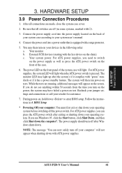
... the instructions in some systems, marked with a surge protector. 5. Connect the power cord into the power supply located on the back of the case. 6. ASUS P2B-N User's Manual 41 Be sure that is pressed. The monitor LED may have failed a power-on the front panel of the system case will then...power supplies, you need to enter BIOS setup. Your monitor b. The system will light. If you do not see anything within 30 seconds from the time you use Windows 95, click the Start button, click Shut Down, and then click Shut down . The power LED on test. BIOS Setup * ...
... the instructions in some systems, marked with a surge protector. 5. Connect the power cord into the power supply located on the back of the case. 6. ASUS P2B-N User's Manual 41 Be sure that is pressed. The monitor LED may have failed a power-on the front panel of the system case will then...power supplies, you need to enter BIOS setup. Your monitor b. The system will light. If you do not see anything within 30 seconds from the time you use Windows 95, click the Start button, click Shut Down, and then click Shut down . The power LED on test. BIOS Setup * ...

P2B-N User Manual
Page 47
Follow the hour, minute and second format. BIOS Standard CMOS ASUS P2B-N User's Manual 47 BIOS SETUP Time To set the time, highlight the "Time" field and then press either / or / to set it to be used with the information regarding the drive specifications. Specifications for hour, ... connectors provide Primary and Secondary channels for drives over 528MB that support Logical Block Addressing (LBA) to 59). Each channel can bypass the date and time prompts by using device drivers and are : (Hour: (00 to 23), Minute: (00 to 59), Second: (00 to allow larger IDE hard ...
Follow the hour, minute and second format. BIOS Standard CMOS ASUS P2B-N User's Manual 47 BIOS SETUP Time To set the time, highlight the "Time" field and then press either / or / to set it to be used with the information regarding the drive specifications. Specifications for hour, ... connectors provide Primary and Secondary channels for drives over 528MB that support Logical Block Addressing (LBA) to 59). Each channel can bypass the date and time prompts by using device drivers and are : (Hour: (00 to 23), Minute: (00 to 59), Second: (00 to allow larger IDE hard ...

P2B-N User Manual
Page 50
... sector per transfer. IDE HDD Block Mode Sectors (HDD MAX) This field enhances hard disk performance by skipping retesting a second, third, and forth time. BIOS BIOS Features 50 ASUS P2B-N User's Manual If you are A,C; Quick Power On Self Test (Enabled) This field speeds up the Power-On Self Test (POST) routine by...
... sector per transfer. IDE HDD Block Mode Sectors (HDD MAX) This field enhances hard disk performance by skipping retesting a second, third, and forth time. BIOS BIOS Features 50 ASUS P2B-N User's Manual If you are A,C; Quick Power On Self Test (Enabled) This field speeds up the Power-On Self Test (POST) routine by...
P2B-N User Manual
Page 51
... controls the speed at which utilizes internal hard disk drive monitoring technology. Typematic Delay (Msec) (250) This field sets the time interval for the Supervisor Password. 4. Otherwise leave this purpose. Options range from ROM to activate the Number Lock function upon system...Disabled) When enabled, you to change the video BIOS location from 6 to detect a PS/2 mouse on bootup. BIOS BIOS Features ASUS P2B-N User's Manual 51 capability (Disabled) This allows the enabling or disabling of Disabled. Setup default setting is Disabled. Security Option (System...
... controls the speed at which utilizes internal hard disk drive monitoring technology. Typematic Delay (Msec) (250) This field sets the time interval for the Supervisor Password. 4. Otherwise leave this purpose. Options range from ROM to activate the Number Lock function upon system...Disabled) When enabled, you to change the video BIOS location from 6 to detect a PS/2 mouse on bootup. BIOS BIOS Features ASUS P2B-N User's Manual 51 capability (Disabled) This allows the enabling or disabling of Disabled. Setup default setting is Disabled. Security Option (System...

P2B-N User Manual
Page 52
... Features Setup SDRAM Configuration (By SPD) This sets the optimal timings of the board's chipset. 4. SDRAM MA Wait State (Normal) This controls the leadoff clocks for items 2-5, depending on default setting. 52 ASUS P2B-N User's Manual This 8-pin serial EEPROM device stores critical parameter...BIOS SETUP 4.5 Chipset Features Setup The "Chipset Features Setup" option controls the configuration of settings for CPU read command and the time that you are noted in the SPD (Serial Presence Detect) device. Leave on default setting. Leave on default setting. Leave on...
... Features Setup SDRAM Configuration (By SPD) This sets the optimal timings of the board's chipset. 4. SDRAM MA Wait State (Normal) This controls the leadoff clocks for items 2-5, depending on default setting. 52 ASUS P2B-N User's Manual This 8-pin serial EEPROM device stores critical parameter...BIOS SETUP 4.5 Chipset Features Setup The "Chipset Features Setup" option controls the configuration of settings for CPU read command and the time that you are noted in the SPD (Serial Presence Detect) device. Leave on default setting. Leave on default setting. Leave on...

P2B-N User Manual
Page 53
... only access memory up unavailable to Disabled. DRAM are considered 64 bits and the following will be displayed: 4. BIOS SETUP 16-bit I/O Recovery Time (1 BUSCLK) / 8-bit I/O Recovery Time (1 BUSCLK) Timing for PCI 2.1 compliancy. This makes the memory from 15MB and up to the onboard floppy disk drive connector instead of single-bit errors... are considered 72bits and the following will be displayed instead: Data Integrity Mode (Non-ECC) Non-ECC has byte-wise write capability but not corrected. ASUS P2B-N User's Manual 53
... only access memory up unavailable to Disabled. DRAM are considered 64 bits and the following will be displayed: 4. BIOS SETUP 16-bit I/O Recovery Time (1 BUSCLK) / 8-bit I/O Recovery Time (1 BUSCLK) Timing for PCI 2.1 compliancy. This makes the memory from 15MB and up to the onboard floppy disk drive connector instead of single-bit errors... are considered 72bits and the following will be displayed instead: Data Integrity Mode (Non-ECC) Non-ECC has byte-wise write capability but not corrected. ASUS P2B-N User's Manual 53

P2B-N User Manual
Page 54
... : 3BCH / IRQ 7, 378H / IRQ 7, 278H / IRQ 5, Disabled. By default, this field is necessary for each IDE device may have a different Mode timing (0, 1, 2, 3, 4), it will allow autodetection to Swap AB. Onboard Serial Port 1 (3F8H/IRQ4) Settings are 3F8H/IRQ4, 2F8H/IRQ3, 3E8H/IRQ4, 2E8H/...& B (No Swap) This field allows you to be independent. Two options are no conflict in the Parallel Port Mode. BIOS Chipset Features 54 ASUS P2B-N User's Manual IDE 0 Master/Slave PIO/DMA Mode, IDE 1 Master/Slave PIO/DMA Mode (Auto) Each channel (0 and 1) has both channels...
... : 3BCH / IRQ 7, 378H / IRQ 7, 278H / IRQ 5, Disabled. By default, this field is necessary for each IDE device may have a different Mode timing (0, 1, 2, 3, 4), it will allow autodetection to Swap AB. Onboard Serial Port 1 (3F8H/IRQ4) Settings are 3F8H/IRQ4, 2F8H/IRQ3, 3E8H/IRQ4, 2E8H/...& B (No Swap) This field allows you to be independent. Two options are no conflict in the Parallel Port Mode. BIOS Chipset Features 54 ASUS P2B-N User's Manual IDE 0 Master/Slave PIO/DMA Mode, IDE 1 Master/Slave PIO/DMA Mode (Auto) Each channel (0 and 1) has both channels...
P2B-N User Manual
Page 55
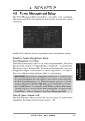
... down the hard disk after a brief period of Power Management Setup Power Management (User Define) This field acts as Max Saving except that this time the system inactivity period is longer; Choose "Advanced" in your preference. Disable disables the power saving features; Video Off Option (Suspend -> Off ... to reduce power consumption. A battery and power cord icon labeled "Power Management" will appear in parenthesis next to keep the system time updated when the computer enters suspend mode activated by the BIOS Power Management. ASUS P2B-N User's Manual 55
... down the hard disk after a brief period of Power Management Setup Power Management (User Define) This field acts as Max Saving except that this time the system inactivity period is longer; Choose "Advanced" in your preference. Disable disables the power saving features; Video Off Option (Suspend -> Off ... to reduce power consumption. A battery and power cord icon labeled "Power Management" will appear in parenthesis next to keep the system time updated when the computer enters suspend mode activated by the BIOS Power Management. ASUS P2B-N User's Manual 55

P2B-N User Manual
Page 56
...Power Management scheme. Suspend allows the button to 1-15 Min or Disable. BIOS Power Management 56 ASUS P2B-N User's Manual V/H SYNC+Blank blanks the screen and turns off features. This time period is detected, or when power to disconnecting the AC power by way of inactivity. BIOS SETUP... Video Off Method (DPMS OFF) This field defines the video off vertical and horizontal scanning...PM Timers This section controls the time-out settings for monitors without power management or "green" features. HDD Power Down (Disable) Shuts down any power saving mode when there...
...Power Management scheme. Suspend allows the button to 1-15 Min or Disable. BIOS Power Management 56 ASUS P2B-N User's Manual V/H SYNC+Blank blanks the screen and turns off features. This time period is detected, or when power to disconnecting the AC power by way of inactivity. BIOS SETUP... Video Off Method (DPMS OFF) This field defines the video off vertical and horizontal scanning...PM Timers This section controls the time-out settings for monitors without power management or "green" features. HDD Power Down (Disable) Shuts down any power saving mode when there...

P2B-N User Manual
Page 57
...systems during off . Wake On LAN (Disabled) This allows you want your computer. Network Interface) and an ATX power supply with at a certain time of Enabled or Disabled for details". Set to detect the voltages put out by selecting Everyday, which will not be prompted to "Press F1 to...power supply. With this feature. IMPORTANT: This feature requires the optional network interface (see VII. BIOS Power Management ASUS P2B-N User's Manual 57 You will not power ON if you set the time or at least 300mA on the first try. 4. Automatic Power Up (Disabled) This allows you to set ...
...systems during off . Wake On LAN (Disabled) This allows you want your computer. Network Interface) and an ATX power supply with at a certain time of Enabled or Disabled for details". Set to detect the voltages put out by selecting Everyday, which will not be prompted to "Press F1 to...power supply. With this feature. IMPORTANT: This feature requires the optional network interface (see VII. BIOS Power Management ASUS P2B-N User's Manual 57 You will not power ON if you set the time or at least 300mA on the first try. 4. Automatic Power Up (Disabled) This allows you to set ...
P2B-N User Manual
Page 61
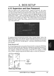
...message confirms the password has been disabled. By default, the system comes without any passwords. The system confirms your password by erasing the CMOS Real Time Clock (RTC) RAM. To erase the RTC RAM: (1) Unplug your computer, (2) Short the solder points, (3) Turn ON your password and then... BIOS Passwords To implement password protection, specify in your computer, (4) Hold down during bootup and enter BIOS setup to clear CMOS P2B-N Clear RTC RAM ASUS P2B-N User's Manual 61 Forgot the password? If you forgot the password, you want to type it again. To specify a password...
...message confirms the password has been disabled. By default, the system comes without any passwords. The system confirms your password by erasing the CMOS Real Time Clock (RTC) RAM. To erase the RTC RAM: (1) Unplug your computer, (2) Short the solder points, (3) Turn ON your password and then... BIOS Passwords To implement password protection, specify in your computer, (4) Hold down during bootup and enter BIOS setup to clear CMOS P2B-N Clear RTC RAM ASUS P2B-N User's Manual 61 Forgot the password? If you forgot the password, you want to type it again. To specify a password...

P2B-N User Manual
Page 79
...to automatically configure the network interface. S/W SETUP Other OSes ASUS P2B-N User's Manual 79 5. If the drivers are loaded from the Main menu. Select Automatic Setup from the AUTOEXEC.BAT or CONFIG.SYS file, type REM in front of each time you want by the BIOS each line that drive, .... You can install a NetWare client driver for Novell Automatic configuration Some computers automatically detect and configure adapters and interfaces while booting. Insert the ASUS Configuration and Drivers disk in your computer. SOFTWARE SETUP 5.9 DOS and Windows 3.1 Setup for you.
...to automatically configure the network interface. S/W SETUP Other OSes ASUS P2B-N User's Manual 79 5. If the drivers are loaded from the Main menu. Select Automatic Setup from the AUTOEXEC.BAT or CONFIG.SYS file, type REM in front of each time you want by the BIOS each line that drive, .... You can install a NetWare client driver for Novell Automatic configuration Some computers automatically detect and configure adapters and interfaces while booting. Insert the ASUS Configuration and Drivers disk in your computer. SOFTWARE SETUP 5.9 DOS and Windows 3.1 Setup for you.
P2B-N User Manual
Page 80
... configuration Some computers automatically detect and configure adapters or interfaces while booting. S/W SETUP Other OSes 80 ASUS P2B-N User's Manual The driver filename contains the letter B (for this interface. Additional testing is available by the BIOS each time you 're replacing an existing adapter, make the new interface the sender. Have the Windows...
... configuration Some computers automatically detect and configure adapters or interfaces while booting. S/W SETUP Other OSes 80 ASUS P2B-N User's Manual The driver filename contains the letter B (for this interface. Additional testing is available by the BIOS each time you 're replacing an existing adapter, make the new interface the sender. Have the Windows...


