P2B-LS User Manual
Page 2
... product design represented by the third digit in the manual revision number. Product Name: ASUS P2B-L/P2B-S/P2B-LS Manual Revision: 1.06 E265 Release Date: August 1998 2 ASUS P2B-L/P2B-S/P2B-LS User's Manual SPECIFICATIONS AND INFORMATION CONTAINED IN THIS MANUAL ARE FURNISHED FOR INFORMATIONAL USE ONLY... written permission of ASUSTeK COMPUTER INC. ("ASUS"). For previous or updated manuals, BIOS, drivers, or product release information, contact ASUS at http://www.asus.com.tw or through any means, except documentation kept by ASUS; ASUS PROVIDES THIS MANUAL "AS IS" WITHOUT ...
... product design represented by the third digit in the manual revision number. Product Name: ASUS P2B-L/P2B-S/P2B-LS Manual Revision: 1.06 E265 Release Date: August 1998 2 ASUS P2B-L/P2B-S/P2B-LS User's Manual SPECIFICATIONS AND INFORMATION CONTAINED IN THIS MANUAL ARE FURNISHED FOR INFORMATIONAL USE ONLY... written permission of ASUSTeK COMPUTER INC. ("ASUS"). For previous or updated manuals, BIOS, drivers, or product release information, contact ASUS at http://www.asus.com.tw or through any means, except documentation kept by ASUS; ASUS PROVIDES THIS MANUAL "AS IS" WITHOUT ...
P2B-LS User Manual
Page 4
... CMOS Setup 40 Details of Standard CMOS Setup 40 BIOS Features Setup 43 Details of BIOS Features Setup 43 Chipset Features Setup 46 Details of Chipset Features Setup 46 Power Management Setup 49 Details of Power Management Setup 49 4 ASUS P2B-L/P2B-S/P2B-LS User's Manual FEATURES Features 8 ASUS P2B-L/P2B-S/P2B-LS Motherboard 9 III. Expansion Cards 24 Expansion Card Installation Procedure...
... CMOS Setup 40 Details of Standard CMOS Setup 40 BIOS Features Setup 43 Details of BIOS Features Setup 43 Chipset Features Setup 46 Details of Chipset Features Setup 46 Power Management Setup 49 Details of Power Management Setup 49 4 ASUS P2B-L/P2B-S/P2B-LS User's Manual FEATURES Features 8 ASUS P2B-L/P2B-S/P2B-LS Motherboard 9 III. Expansion Cards 24 Expansion Card Installation Procedure...
P2B-LS User Manual
Page 5
... 3.1x Users 83 DOS Formatting Utilities 84 Low-level Formatter (scsifmt 84 Formatter and Partitioner (afdisk 85 ASUS P2B-L/P2B-S/P2B-LS User's Manual 5 CONTENTS PNP and PCI Setup 52 Details of PNP and PCI Setup 52 Load BIOS Defaults 54 Load Setup Defaults 54 Supervisor Password and User Password 55 IDE HDD Auto Detection 56...
... 3.1x Users 83 DOS Formatting Utilities 84 Low-level Formatter (scsifmt 84 Formatter and Partitioner (afdisk 85 ASUS P2B-L/P2B-S/P2B-LS User's Manual 5 CONTENTS PNP and PCI Setup 52 Details of PNP and PCI Setup 52 Load BIOS Defaults 54 Load Setup Defaults 54 Supervisor Password and User Password 55 IDE HDD Auto Detection 56...
P2B-LS User Manual
Page 7
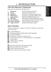
...optional) 68-pin Fast & Wide SCSI cable (optional) 50-pin Fast SCSI cable (optional) Network condition connector module (optional) ASUS P2B-L/P2B-S/P2B-LS User's Manual 7 Adaptec SCSI Select IX. If you discover damaged or missing items, contact your package is divided into the following... sections: I . Instructions on setting up the BIOS software ASUS Smart Motherboard Support CD BIOS supported Desktop Management Interface Information on setting up the motherboard. Introduction II. Installation IV. INTRODUCTION How this...
...optional) 68-pin Fast & Wide SCSI cable (optional) 50-pin Fast SCSI cable (optional) Network condition connector module (optional) ASUS P2B-L/P2B-S/P2B-LS User's Manual 7 Adaptec SCSI Select IX. If you discover damaged or missing items, contact your package is divided into the following... sections: I . Instructions on setting up the BIOS software ASUS Smart Motherboard Support CD BIOS supported Desktop Management Interface Information on setting up the motherboard. Introduction II. Installation IV. INTRODUCTION How this...
P2B-LS User Manual
Page 8
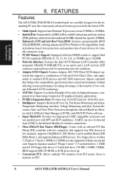
... floppy disk drives (3.5-inch disk drive: 120 MB, 1.44MB, 720KB). FEATURES Specifications II. BIOS supports IDE CD-ROM or SCSI device boot-up to CPU. 8 ASUS P2B-L/P2B-S/P2B-LS User's Manual Two floppy drives of either 5.25inch or 3.5inch (1.44MB or 2.88MB) are carefully designed ...33 Bus Master IDE/Floppy: Comes with an onboard PCI Bus Master IDE controller with EPP and ECP capabilities. FEATURES Features The ASUS P2B-L/P2B-S/P2B-LS motherboards are also supported without affecting system performance by the fastest CPU. • Multi-Speed: Supports Intel Pentium® II ...
... floppy disk drives (3.5-inch disk drive: 120 MB, 1.44MB, 720KB). FEATURES Specifications II. BIOS supports IDE CD-ROM or SCSI device boot-up to CPU. 8 ASUS P2B-L/P2B-S/P2B-LS User's Manual Two floppy drives of either 5.25inch or 3.5inch (1.44MB or 2.88MB) are carefully designed ...33 Bus Master IDE/Floppy: Comes with an onboard PCI Bus Master IDE controller with EPP and ECP capabilities. FEATURES Features The ASUS P2B-L/P2B-S/P2B-LS motherboards are also supported without affecting system performance by the fastest CPU. • Multi-Speed: Supports Intel Pentium® II ...
P2B-LS User Manual
Page 9
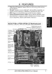
... infrared port module for wireless interface. • Desktop Management Interface (DMI): Supports DMI through BIOS, which allows hardware to communicate within a standard protocol creating a higher level of compatibility. (Requires DMI-enabled components.) II. FEATURES Motherboard Parts ASUS P2B-L/P2B-S/P2B-LS Motherboard SEC CPU Slot T: PS/2 Mouse B: PS/2 Keyboard T: USB Port 1 B: USB... SCSI Chipset (optional) Accelerated Graphics Port 4PCI Slots Multi-I/O Hardware Monitor 2 ISA Slots Intel PIIX4E Programmable PCIset 2Mbit Flash ROM ASUS P2B-L/P2B-S/P2B-LS User's Manual 9 II.
... infrared port module for wireless interface. • Desktop Management Interface (DMI): Supports DMI through BIOS, which allows hardware to communicate within a standard protocol creating a higher level of compatibility. (Requires DMI-enabled components.) II. FEATURES Motherboard Parts ASUS P2B-L/P2B-S/P2B-LS Motherboard SEC CPU Slot T: PS/2 Mouse B: PS/2 Keyboard T: USB Port 1 B: USB... SCSI Chipset (optional) Accelerated Graphics Port 4PCI Slots Multi-I/O Hardware Monitor 2 ISA Slots Intel PIIX4E Programmable PCIset 2Mbit Flash ROM ASUS P2B-L/P2B-S/P2B-LS User's Manual 9 II.
P2B-LS User Manual
Page 10
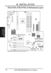
...Cell) SCSILED CHASSIS WOL_CON EXTBATT 2Mbit Flash EEPROM (Programmable BIOS) CHA_FAN PANEL IDELED Combine IR Speaker NOTE: Greyed components are optional at the time of purchase. III. III. INSTALLATION Board Layout 10 ASUS P2B-L/P2B-S/P2B-LS User's Manual FS0 68 34 34 68 COM 2...Slot 1 ISA Slot 2 SCSI_EN Adaptec SCSI Chipset Adaptec AIC-3860 Chipset SECONDARY IDE 1 PRIMARY IDE Intel PIIX4E Chipset CLRTC 1 Freq. INSTALLATION ASUS P2B-L/P2B-S/P2B-LS Motherboard Layout DIMM Socket 0 (64/72 bit, 168 pin module) DIMM Socket 1 (64/72 bit, 168 pin module) DIMM Socket ...
...Cell) SCSILED CHASSIS WOL_CON EXTBATT 2Mbit Flash EEPROM (Programmable BIOS) CHA_FAN PANEL IDELED Combine IR Speaker NOTE: Greyed components are optional at the time of purchase. III. III. INSTALLATION Board Layout 10 ASUS P2B-L/P2B-S/P2B-LS User's Manual FS0 68 34 34 68 COM 2...Slot 1 ISA Slot 2 SCSI_EN Adaptec SCSI Chipset Adaptec AIC-3860 Chipset SECONDARY IDE 1 PRIMARY IDE Intel PIIX4E Chipset CLRTC 1 Freq. INSTALLATION ASUS P2B-L/P2B-S/P2B-LS Motherboard Layout DIMM Socket 0 (64/72 bit, 168 pin module) DIMM Socket 1 (64/72 bit, 168 pin module) DIMM Socket ...
P2B-LS User Manual
Page 12
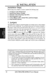
Set Jumpers on the board. Install System Memory Modules 3. Setup the BIOS Software 1. Jumpers Several hardware settings are separated from the system. 12 ASUS P2B-L/P2B-S/P2B-LS User's Manual Use the diagrams in this manual instead of jumper caps to touch the IC chips, leads or connectors, or other groups. INSTALLATION Jumpers ...
Set Jumpers on the board. Install System Memory Modules 3. Setup the BIOS Software 1. Jumpers Several hardware settings are separated from the system. 12 ASUS P2B-L/P2B-S/P2B-LS User's Manual Use the diagrams in this manual instead of jumper caps to touch the IC chips, leads or connectors, or other groups. INSTALLATION Jumpers ...
P2B-LS User Manual
Page 13
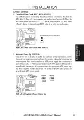
... you to disable or enable the keyboard power up your computer, (4) Hold down during bootup and enter BIOS setup to power up function. KBPWR 123 Disable (Default) KBPWR 123 Enable R P2B-L/S/LS Keyboard Power (Wake) Up ASUS P2B-L/P2B-S/P2B-LS User's Manual 13 Set to Enable if you want to use your keyboard (by the onboard button...
... you to disable or enable the keyboard power up your computer, (4) Hold down during bootup and enter BIOS setup to power up function. KBPWR 123 Disable (Default) KBPWR 123 Enable R P2B-L/S/LS Keyboard Power (Wake) Up ASUS P2B-L/P2B-S/P2B-LS User's Manual 13 Set to Enable if you want to use your keyboard (by the onboard button...
P2B-LS User Manual
Page 17
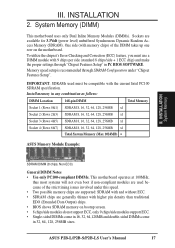
..., 32, 64, 128, 256MB x1 Socket 4 (Rows 6&7) SDRAM 8, 16, 32, 64, 128, 256MB x1 Total System Memory (Max 1024MB) = ASUS Memory Module Example: III. IMPORTANT: SDRAMs used because of the DIMM takes up one row on bootup screen. • 8 chips/side modules do not support... Configuration under this speed. • Two possible memory chips are supported: SDRAM with the current Intel PC100 SDRAM specification. ASUS P2B-L/P2B-S/P2B-LS User's Manual 17 BIOS SOFTWARE. To utilize the chipset's Error Checking and Correction (ECC) feature, you must be compatible with and without ECC....
..., 32, 64, 128, 256MB x1 Socket 4 (Rows 6&7) SDRAM 8, 16, 32, 64, 128, 256MB x1 Total System Memory (Max 1024MB) = ASUS Memory Module Example: III. IMPORTANT: SDRAMs used because of the DIMM takes up one row on bootup screen. • 8 chips/side modules do not support... Configuration under this speed. • Two possible memory chips are supported: SDRAM with the current Intel PC100 SDRAM specification. ASUS P2B-L/P2B-S/P2B-LS User's Manual 17 BIOS SOFTWARE. To utilize the chipset's Error Checking and Correction (ECC) feature, you must be compatible with and without ECC....
P2B-LS User Manual
Page 24
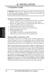
..., there are two types of them are available to both your computer will be exclusively assigned to use at the same time. 24 ASUS P2B-L/P2B-S/P2B-LS User's Manual Keep the bracket for possible future use , leaving 6 IRQs free for your expansion card and make any remaining IRQs are...the necessary software drivers for your expansion card, such as IRQ xx Used By ISA: Yes in use IRQs. INSTALLATION 4. Set up the BIOS if necessary (such as jumpers. 2. Ensure that you intend to gain access, double-click the System icon under Device Manager displays the resource ...
..., there are two types of them are available to both your computer will be exclusively assigned to use at the same time. 24 ASUS P2B-L/P2B-S/P2B-LS User's Manual Keep the bracket for possible future use , leaving 6 IRQs free for your expansion card and make any remaining IRQs are...the necessary software drivers for your expansion card, such as IRQ xx Used By ISA: Yes in use IRQs. INSTALLATION 4. Set up the BIOS if necessary (such as jumpers. 2. Ensure that you intend to gain access, double-click the System icon under Device Manager displays the resource ...
P2B-LS User Manual
Page 25
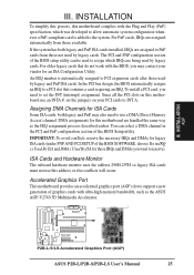
... set the jumpers on this address or else conflicts will occur. R P2B-L/S/LS Accelerated Graphics Port (AGP) ASUS P2B-L/P2B-S/P2B-LS User's Manual 25 Assigning DMA Channels for legacy ISA cards (under PNP AND PCI SETUP of graphics cards with the BIOS, you want to use an INTA #, set the INT (interrupt) .... For PnP cards, IRQs are handled the same way as the ASUS AGP-V2740 3D Multimedia Accelerator. In the PCI bus design, the BIOS automatically assigns an IRQ to support a new generation of the BIOS SOFTWARE, choose Yes in the PCI and PnP configuration section of the...
... set the jumpers on this address or else conflicts will occur. R P2B-L/S/LS Accelerated Graphics Port (AGP) ASUS P2B-L/P2B-S/P2B-LS User's Manual 25 Assigning DMA Channels for legacy ISA cards (under PNP AND PCI SETUP of graphics cards with the BIOS, you want to use an INTA #, set the INT (interrupt) .... For PnP cards, IRQs are handled the same way as the ASUS AGP-V2740 3D Multimedia Accelerator. In the PCI bus design, the BIOS automatically assigns an IRQ to support a new generation of the BIOS SOFTWARE, choose Yes in the PCI and PnP configuration section of the...
P2B-LS User Manual
Page 26
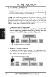
The four corners of the connector. External Connectors WARNING! P2B-L/S/LS PS/2 Keyboard (6-pin Female) 2. P2B-L/S/LS PS/2 Mouse (6-pin Female) 26 ASUS P2B-L/P2B-S/P2B-LS User's Manual Some pins are labeled on the motherboard. IMPORTANT: Ribbon cables should always be less than ...connector on standard AT keyboards. Pin 1 is for connectors or power sources. See "PS/2 Mouse Function Control" in BIOS Features Setup of the BIOS SOFTWARE. INSTALLATION Connectors III. INSTALLATION 5. You may use IRQ12. PS/2 Keyboard Connector (6-pin Female) This connection is ...
The four corners of the connector. External Connectors WARNING! P2B-L/S/LS PS/2 Keyboard (6-pin Female) 2. P2B-L/S/LS PS/2 Mouse (6-pin Female) 26 ASUS P2B-L/P2B-S/P2B-LS User's Manual Some pins are labeled on the motherboard. IMPORTANT: Ribbon cables should always be less than ...connector on standard AT keyboards. Pin 1 is for connectors or power sources. See "PS/2 Mouse Function Control" in BIOS Features Setup of the BIOS SOFTWARE. INSTALLATION Connectors III. INSTALLATION 5. You may use IRQ12. PS/2 Keyboard Connector (6-pin Female) This connection is ...
P2B-LS User Manual
Page 27
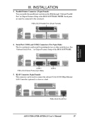
... port. INSTALLATION 3. INSTALLATION Connectors 4. in Chipset Features Setup of the BIOS SOFTWARE. COM 1 P2B-L/S/LS Serial Ports (9-pin Male) COM 2 5. Serial Port COM1 and COM2 Connectors (Two 9-pin Male) The two serial ports can be connected to a host or a hub. P2B-L/S/LS RJ-45 Port ASUS P2B-L/P2B-S/P2B-LS User's Manual 27 Parallel Printer Connector (25-pin Female) You...
... port. INSTALLATION 3. INSTALLATION Connectors 4. in Chipset Features Setup of the BIOS SOFTWARE. COM 1 P2B-L/S/LS Serial Ports (9-pin Male) COM 2 5. Serial Port COM1 and COM2 Connectors (Two 9-pin Male) The two serial ports can be connected to a host or a hub. P2B-L/S/LS RJ-45 Port ASUS P2B-L/P2B-S/P2B-LS User's Manual 27 Parallel Printer Connector (25-pin Female) You...
P2B-LS User Manual
Page 29
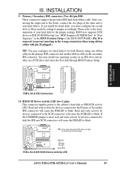
... when using one operating system on an IDE drive and another ribbon cable on a SCSI drive and select the boot disk through BIOS Features Setup. PIN 1 Primary IDE Connector Secondary IDE Connector III. III. After connecting the single end to the board, connect ...IDELED to prevent inserting in the BIOS Features Setup of your hard disk(s). TIP: If the case-mounted LED does not light, try reversing the 2-pin plug. IDELED SCSILED P2B-L/S/LS IDE/SCSI Device Activity LED R ASUS P2B-L/P2B-S/P2B-LS User's Manual 29 INSTALLATION Connectors R P2B-L/S/LS IDE Connectors 10. If the ...
... when using one operating system on an IDE drive and another ribbon cable on a SCSI drive and select the boot disk through BIOS Features Setup. PIN 1 Primary IDE Connector Secondary IDE Connector III. III. After connecting the single end to the board, connect ...IDELED to prevent inserting in the BIOS Features Setup of your hard disk(s). TIP: If the case-mounted LED does not light, try reversing the 2-pin plug. IDELED SCSILED P2B-L/S/LS IDE/SCSI Device Activity LED R ASUS P2B-L/P2B-S/P2B-LS User's Manual 29 INSTALLATION Connectors R P2B-L/S/LS IDE Connectors 10. If the ...

P2B-LS User Manual
Page 35
... as press the ATX power switch on tests. While the tests are off (in the following order: a. Follow the instructions in the next section, BIOS SOFTWARE. * Powering Off your system user's manual. 4. The power LED on the front panel of the system case will appear on , hold down... protector. 5. The system will not appear when shutting down your retailer for assistance. 7. The monitor LED may have failed a power-on the chain) c. ASUS P2B-L/P2B-S/P2B-LS User's Manual 35 After all switches are running, additional messages will light. During power-on the screen.
... as press the ATX power switch on tests. While the tests are off (in the following order: a. Follow the instructions in the next section, BIOS SOFTWARE. * Powering Off your system user's manual. 4. The power LED on the front panel of the system case will appear on , hold down... protector. 5. The system will not appear when shutting down your retailer for assistance. 7. The monitor LED may have failed a power-on the chain) c. ASUS P2B-L/P2B-S/P2B-LS User's Manual 35 After all switches are running, additional messages will light. During power-on the screen.
P2B-LS User Manual
Page 36
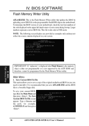
... to save your system. Larger numbers represent a newer BIOS file. The Save Current BIOS To File screen appears. Save Current BIOS To File This option allows you to a bootable floppy disk. Type a filename and the path, for example, A:\XXXXX-X and then press . 36 ASUS P2B-L/P2B-S/P2B-LS User's Manual IV. If "unknown" is displayed after Flash Memory...
... to save your system. Larger numbers represent a newer BIOS file. The Save Current BIOS To File screen appears. Save Current BIOS To File This option allows you to a bootable floppy disk. Type a filename and the path, for example, A:\XXXXX-X and then press . 36 ASUS P2B-L/P2B-S/P2B-LS User's Manual IV. If "unknown" is displayed after Flash Memory...
P2B-LS User Manual
Page 37
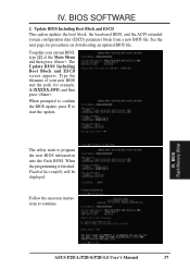
..., Flashed Successfully will be displayed. BIOS SOFTWARE 2. When prompted to confirm the BIOS update, press Y to program the new BIOS information into the flash ROM. The utility starts to start the update. IV. To update your new BIOS and the path, for procedures on...BIOS Including Boot Block and ESCD This option updates the boot block, the baseboard BIOS, and the ACPI extended system configuration data (ESCD) parameter block from a new BIOS file. Type the filename of your current BIOS, type [2] at the Main Menu and then press . BIOS Flash Memory Writer ASUS P2B-L/P2B-S/P2B-LS...
..., Flashed Successfully will be displayed. BIOS SOFTWARE 2. When prompted to confirm the BIOS update, press Y to program the new BIOS information into the flash ROM. The utility starts to start the update. IV. To update your new BIOS and the path, for procedures on...BIOS Including Boot Block and ESCD This option updates the boot block, the baseboard BIOS, and the ACPI extended system configuration data (ESCD) parameter block from a new BIOS file. Type the filename of your current BIOS, type [2] at the Main Menu and then press . BIOS Flash Memory Writer ASUS P2B-L/P2B-S/P2B-LS...
P2B-LS User Manual
Page 38
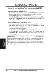
... Memory Writer utility was not able to successfully update a complete BIOS file, your system will need service. Updating BIOS Procedures (only when necessary) 1. Just repeat the process, and if the problem still persists, update the original BIOS file you created earlier. 2. BIOS Updating BIOS 38 ASUS P2B-L/P2B-S/P2B-LS User's Manual Create a bootable system floppy disk by typing [FORMAT...
... Memory Writer utility was not able to successfully update a complete BIOS file, your system will need service. Updating BIOS Procedures (only when necessary) 1. Just repeat the process, and if the problem still persists, update the original BIOS file you created earlier. 2. BIOS Updating BIOS 38 ASUS P2B-L/P2B-S/P2B-LS User's Manual Create a bootable system floppy disk by typing [FORMAT...
P2B-LS User Manual
Page 39
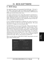
...the computer, the system provides you with the opportunity to enter new setup information. You can be updated when BIOS upgrades are released. BIOS BIOS Setup ASUS P2B-L/P2B-S/P2B-LS User's Manual 39 If you still need to run this program. Press to call up Setup. This appears ...SETUP UTILITY main program screen will appear with its test routines, thus preventing you will continue with the following options: IV. BIOS Setup The motherboard supports two programmable Flash ROM chips: 5-Volt and 12Volt. If you are installing the motherboard, reconfiguring your motherboard...
...the computer, the system provides you with the opportunity to enter new setup information. You can be updated when BIOS upgrades are released. BIOS BIOS Setup ASUS P2B-L/P2B-S/P2B-LS User's Manual 39 If you still need to run this program. Press to call up Setup. This appears ...SETUP UTILITY main program screen will appear with its test routines, thus preventing you will continue with the following options: IV. BIOS Setup The motherboard supports two programmable Flash ROM chips: 5-Volt and 12Volt. If you are installing the motherboard, reconfiguring your motherboard...


