
P2B-L User Manual
Page 2
...BIOS, drivers, or product release information, contact ASUS at http://www.asus.com.tw or through any means, except documentation kept by the purchaser for backup purposes, without intent to the owners' benefit, without the express written permission of ASUSTeK COMPUTER INC. ("ASUS"). IN NO EVENT SHALL ASUS... APPEAR IN THIS MANUAL, INCLUDING THE PRODUCTS AND SOFTWARE DESCRIBED IN IT. Product Name: ASUS P2B-L/P2B-S/P2B-LS Manual Revision: 1.06 E265 Release Date: August 1998 2 ASUS P2B-L/P2B-S/P2B-LS User's Manual The product name and revision number are represented by the third digit in...
...BIOS, drivers, or product release information, contact ASUS at http://www.asus.com.tw or through any means, except documentation kept by the purchaser for backup purposes, without intent to the owners' benefit, without the express written permission of ASUSTeK COMPUTER INC. ("ASUS"). IN NO EVENT SHALL ASUS... APPEAR IN THIS MANUAL, INCLUDING THE PRODUCTS AND SOFTWARE DESCRIBED IN IT. Product Name: ASUS P2B-L/P2B-S/P2B-LS Manual Revision: 1.06 E265 Release Date: August 1998 2 ASUS P2B-L/P2B-S/P2B-LS User's Manual The product name and revision number are represented by the third digit in...
P2B-L User Manual
Page 4
... 12 Jumper Settings 13 2. External Connectors 26 Power Connection Procedures 35 IV. BIOS SOFTWARE Main Menu 36 Flash Memory Writer Utility 36 Managing and Updating Your Motherboard's BIOS 38 6. System Memory (DIMM 17 DIMM Memory Installation Procedures 18 3. FEATURES Features 8 ASUS P2B-L/P2B-S/P2B-LS Motherboard 9 III. Expansion Cards 24 Expansion Card Installation Procedure 24 Assigning...
... 12 Jumper Settings 13 2. External Connectors 26 Power Connection Procedures 35 IV. BIOS SOFTWARE Main Menu 36 Flash Memory Writer Utility 36 Managing and Updating Your Motherboard's BIOS 38 6. System Memory (DIMM 17 DIMM Memory Installation Procedures 18 3. FEATURES Features 8 ASUS P2B-L/P2B-S/P2B-LS Motherboard 9 III. Expansion Cards 24 Expansion Card Installation Procedure 24 Assigning...

P2B-L User Manual
Page 5
...and Windows 3.1 Setup for DOS/Windows 3.1x Users 83 DOS Formatting Utilities 84 Low-level Formatter (scsifmt 84 Formatter and Partitioner (afdisk 85 ASUS P2B-L/P2B-S/P2B-LS User's Manual 5 ADAPTEC SCSI SELECT Configuring the SCSI Adapter 77 SCSI Disk Utilities 77 IX. ADAPTEC EZ-SCSI UTILITY Quick Start Instructions 79...58 Main Menu Selections 59 Other CD Directories 59 VI. CONTENTS PNP and PCI Setup 52 Details of PNP and PCI Setup 52 Load BIOS Defaults 54 Load Setup Defaults 54 Supervisor Password and User Password 55 IDE HDD Auto Detection 56 Save & Exit Setup 57 Exit Without...
...and Windows 3.1 Setup for DOS/Windows 3.1x Users 83 DOS Formatting Utilities 84 Low-level Formatter (scsifmt 84 Formatter and Partitioner (afdisk 85 ASUS P2B-L/P2B-S/P2B-LS User's Manual 5 ADAPTEC SCSI SELECT Configuring the SCSI Adapter 77 SCSI Disk Utilities 77 IX. ADAPTEC EZ-SCSI UTILITY Quick Start Instructions 79...58 Main Menu Selections 59 Other CD Directories 59 VI. CONTENTS PNP and PCI Setup 52 Details of PNP and PCI Setup 52 Load BIOS Defaults 54 Load Setup Defaults 54 Supervisor Password and User Password 55 IDE HDD Auto Detection 56 Save & Exit Setup 57 Exit Without...

P2B-L User Manual
Page 7
...(optional) Adaptec SCSI Select utility (optional) Adaptec EZ-SCSI utility (optional) Item Checklist Check that your retailer. (1) ASUS Motherboard (1) Retention mechanism & heatsink support for CPU and heatsink (2) Attach mount bridges (1) IDE ribbon cable for master and...optional) 50-pin Fast SCSI cable (optional) Network condition connector module (optional) ASUS P2B-L/P2B-S/P2B-LS User's Manual 7 Instructions on setting up the BIOS software ASUS Smart Motherboard Support CD BIOS supported Desktop Management Interface Information on setting up the motherboard. I . INTRODUCTION Manual ...
...(optional) Adaptec SCSI Select utility (optional) Adaptec EZ-SCSI utility (optional) Item Checklist Check that your retailer. (1) ASUS Motherboard (1) Retention mechanism & heatsink support for CPU and heatsink (2) Attach mount bridges (1) IDE ribbon cable for master and...optional) 50-pin Fast SCSI cable (optional) Network condition connector module (optional) ASUS P2B-L/P2B-S/P2B-LS User's Manual 7 Instructions on setting up the BIOS software ASUS Smart Motherboard Support CD BIOS supported Desktop Management Interface Information on setting up the motherboard. I . INTRODUCTION Manual ...
P2B-L User Manual
Page 8
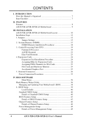
... performance by the fastest CPU. • Multi-Speed: Supports Intel Pentium® II processors from 233MHz to CPU. 8 ASUS P2B-L/P2B-S/P2B-LS User's Manual BIOS supports IDE CD-ROM or SCSI device boot-up. • Concurrent PCI: Allows multiple PCI transfers from COM2 to the ...(FSB) platform, which boosts the traditional 66-MHz internal bus speed to 100MHz. • Enhanced ACPI and Anti-Boot Virus BIOS: Features a programmable BIOS (Flash EEPROM), offering enhanced ACPI for Windows 98 compatibility, builtin hardware-based virus protection, and autodetection of most devices for virtually...
... performance by the fastest CPU. • Multi-Speed: Supports Intel Pentium® II processors from 233MHz to CPU. 8 ASUS P2B-L/P2B-S/P2B-LS User's Manual BIOS supports IDE CD-ROM or SCSI device boot-up. • Concurrent PCI: Allows multiple PCI transfers from COM2 to the ...(FSB) platform, which boosts the traditional 66-MHz internal bus speed to 100MHz. • Enhanced ACPI and Anti-Boot Virus BIOS: Features a programmable BIOS (Flash EEPROM), offering enhanced ACPI for Windows 98 compatibility, builtin hardware-based virus protection, and autodetection of most devices for virtually...

P2B-L User Manual
Page 9
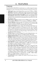
... infrared port module for wireless interface. • Desktop Management Interface (DMI): Supports DMI through BIOS, which allows hardware to communicate within a standard protocol creating a higher level of compatibility. (Requires DMI-enabled components.) II. FEATURES Motherboard Parts ASUS P2B-L/P2B-S/P2B-LS Motherboard SEC CPU Slot T: PS/2 Mouse B: PS/2 Keyboard T: USB Port 1 B:.../ Wide SCSI Chipset (optional) Accelerated Graphics Port 4PCI Slots Multi-I/O Hardware Monitor 2 ISA Slots Intel PIIX4E Programmable PCIset 2Mbit Flash ROM ASUS P2B-L/P2B-S/P2B-LS User's Manual 9
... infrared port module for wireless interface. • Desktop Management Interface (DMI): Supports DMI through BIOS, which allows hardware to communicate within a standard protocol creating a higher level of compatibility. (Requires DMI-enabled components.) II. FEATURES Motherboard Parts ASUS P2B-L/P2B-S/P2B-LS Motherboard SEC CPU Slot T: PS/2 Mouse B: PS/2 Keyboard T: USB Port 1 B:.../ Wide SCSI Chipset (optional) Accelerated Graphics Port 4PCI Slots Multi-I/O Hardware Monitor 2 ISA Slots Intel PIIX4E Programmable PCIset 2Mbit Flash ROM ASUS P2B-L/P2B-S/P2B-LS User's Manual 9
P2B-L User Manual
Page 10
INSTALLATION ASUS P2B-L/P2B-S/P2B-LS Motherboard Layout DIMM Socket 0 (64/72 bit, 168 pin module) DIMM Socket 1 (64/72 bit, 168 pin module) DIMM Socket 2 (64/72 bit, 168 ... (CR2032 3V Lithium Cell) SCSILED CHASSIS WOL_CON EXTBATT 2Mbit Flash EEPROM (Programmable BIOS) CHA_FAN PANEL IDELED Combine IR Speaker NOTE: Greyed components are optional at the time of purchase. INSTALLATION Board Layout 10 ASUS P2B-L/P2B-S/P2B-LS User's Manual FS0 68 34 34 68 COM 2 RJ-45 1 FLOPPY LAN Activity LED Connector 35 1 35...
INSTALLATION ASUS P2B-L/P2B-S/P2B-LS Motherboard Layout DIMM Socket 0 (64/72 bit, 168 pin module) DIMM Socket 1 (64/72 bit, 168 pin module) DIMM Socket 2 (64/72 bit, 168 ... (CR2032 3V Lithium Cell) SCSILED CHASSIS WOL_CON EXTBATT 2Mbit Flash EEPROM (Programmable BIOS) CHA_FAN PANEL IDELED Combine IR Speaker NOTE: Greyed components are optional at the time of purchase. INSTALLATION Board Layout 10 ASUS P2B-L/P2B-S/P2B-LS User's Manual FS0 68 34 34 68 COM 2 RJ-45 1 FLOPPY LAN Activity LED Connector 35 1 35...

P2B-L User Manual
Page 12
III. Install the Central Processing Unit (CPU) 4. Jumpers Several hardware settings are separated from the system. 12 ASUS P2B-L/P2B-S/P2B-LS User's Manual Jumpers with two pins will be shown graphi- III. Unplug your computer, you must complete the following the pin layout on the ... to a safely grounded object or to connect jumper pins (JP) on the board. Use the diagrams in this manual instead of your computer. 1. Setup the BIOS Software 1. Install Expansion Cards 5. Settings with two jumper numbers require that came with three pins.
III. Install the Central Processing Unit (CPU) 4. Jumpers Several hardware settings are separated from the system. 12 ASUS P2B-L/P2B-S/P2B-LS User's Manual Jumpers with two pins will be shown graphi- III. Unplug your computer, you must complete the following the pin layout on the ... to a safely grounded object or to connect jumper pins (JP) on the board. Use the diagrams in this manual instead of your computer. 1. Setup the BIOS Software 1. Install Expansion Cards 5. Settings with two jumper numbers require that came with three pins.
P2B-L User Manual
Page 13
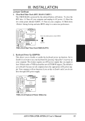
...down during bootup and enter BIOS setup to use your keyboard (by the onboard button cell battery. Your computer will not function if you do not have the appropriate ATX power supply. KBPWR 123 Disable (Default) KBPWR 123 Enable R P2B-L/S/LS Keyboard Power (Wake) Up ASUS P2B-L/P2B-S/P2B-LS User's Manual 13 To... computer and unplug its AC power, (2) Short the two solder points labeled CLRTC, (3) Turn on the +5VSB lead and the new ACPI BIOS support. Set to Enable if you to Disable because not all computers have the right ATX power supply. INSTALLATION Jumpers III. The default is...
...down during bootup and enter BIOS setup to use your keyboard (by the onboard button cell battery. Your computer will not function if you do not have the appropriate ATX power supply. KBPWR 123 Disable (Default) KBPWR 123 Enable R P2B-L/S/LS Keyboard Power (Wake) Up ASUS P2B-L/P2B-S/P2B-LS User's Manual 13 To... computer and unplug its AC power, (2) Short the two solder points labeled CLRTC, (3) Turn on the +5VSB lead and the new ACPI BIOS support. Set to Enable if you to Disable because not all computers have the right ATX power supply. INSTALLATION Jumpers III. The default is...
P2B-L User Manual
Page 17
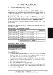
...Setup". Memory speed setup is recommended through "Chipset Features Setup" in IV. Install memory in 32, 64, 128, 256MB sizes. ASUS P2B-L/P2B-S/P2B-LS User's Manual 17 System Memory (DIMM) This motherboard uses only Dual Inline Memory Modules (DIMMs). INSTALLATION 2. To utilize the ... possible memory chips are supported: SDRAM with higher pin density than traditional EDO (Extended Data Output) chips. • BIOS shows SDRAM memory on the motherboard. BIOS SOFTWARE. III. INSTALLATION System Memory SDRAM DIMM (8 chips, Non-ECC) General DIMM Notes • Use only PC100...
...Setup". Memory speed setup is recommended through "Chipset Features Setup" in IV. Install memory in 32, 64, 128, 256MB sizes. ASUS P2B-L/P2B-S/P2B-LS User's Manual 17 System Memory (DIMM) This motherboard uses only Dual Inline Memory Modules (DIMMs). INSTALLATION 2. To utilize the ... possible memory chips are supported: SDRAM with higher pin density than traditional EDO (Extended Data Output) chips. • BIOS shows SDRAM memory on the motherboard. BIOS SOFTWARE. III. INSTALLATION System Memory SDRAM DIMM (8 chips, Non-ECC) General DIMM Notes • Use only PC100...

P2B-L User Manual
Page 24
... IRQs are available to cards installed in the ISA expansion bus first, then any remaining IRQs are in use at the same time. 24 ASUS P2B-L/P2B-S/P2B-LS User's Manual INSTALLATION Expansion Cards III. Failure to do so may cause severe damage to PCI cards. Currently, there are already in ... use the Microsoft Diagnostics (MSD.EXE) utility located in use Windows 95, the Resources tab under the Control Panel program). Set up the BIOS if necessary (such as IRQ xx Used By ISA: Yes in any necessary hardware or software settings for Expansion Cards Some expansion cards need...
... IRQs are available to cards installed in the ISA expansion bus first, then any remaining IRQs are in use at the same time. 24 ASUS P2B-L/P2B-S/P2B-LS User's Manual INSTALLATION Expansion Cards III. Failure to do so may cause severe damage to PCI cards. Currently, there are already in ... use the Microsoft Diagnostics (MSD.EXE) utility located in use Windows 95, the Resources tab under the Control Panel program). Set up the BIOS if necessary (such as IRQ xx Used By ISA: Yes in any necessary hardware or software settings for Expansion Cards Some expansion cards need...

P2B-L User Manual
Page 25
... card is automatically assigned to PCI expansion cards after those IRQs and DMAs you need to reserve). R P2B-L/S/LS Accelerated Graphics Port (AGP) ASUS P2B-L/P2B-S/P2B-LS User's Manual 25 INSTALLATION To simplify this process, this motherboard are assigned automatically from those available. ...IMPORTANT: To avoid conflicts, reserve the necessary IRQs and DMAs for legacy ISA cards (under PNP AND PCI SETUP of the BIOS SOFTWARE...
... card is automatically assigned to PCI expansion cards after those IRQs and DMAs you need to reserve). R P2B-L/S/LS Accelerated Graphics Port (AGP) ASUS P2B-L/P2B-S/P2B-LS User's Manual 25 INSTALLATION To simplify this process, this motherboard are assigned automatically from those available. ...IMPORTANT: To avoid conflicts, reserve the necessary IRQs and DMAs for legacy ISA cards (under PNP AND PCI SETUP of the BIOS SOFTWARE...
P2B-L User Manual
Page 26
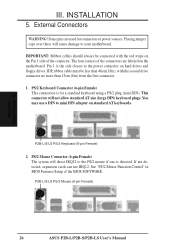
External Connectors WARNING! This connector will cause damage to the PS/2 mouse if one is detected. P2B-L/S/LS PS/2 Keyboard (6-pin Female) 2. P2B-L/S/LS PS/2 Mouse (6-pin Female) 26 ASUS P2B-L/P2B-S/P2B-LS User's Manual Some pins are labeled on the Pin 1 side of the connector. IDE ribbon ... for a standard keyboard using a PS/2 plug (mini DIN). Pin 1 is for connectors or power sources. The four corners of the BIOS SOFTWARE. IMPORTANT: Ribbon cables should always be less than 46cm(18in), with the red stripe on the motherboard. PS/2 Keyboard Connector (6-pin ...
External Connectors WARNING! This connector will cause damage to the PS/2 mouse if one is detected. P2B-L/S/LS PS/2 Keyboard (6-pin Female) 2. P2B-L/S/LS PS/2 Mouse (6-pin Female) 26 ASUS P2B-L/P2B-S/P2B-LS User's Manual Some pins are labeled on the Pin 1 side of the connector. IDE ribbon ... for a standard keyboard using a PS/2 plug (mini DIN). Pin 1 is for connectors or power sources. The four corners of the BIOS SOFTWARE. IMPORTANT: Ribbon cables should always be less than 46cm(18in), with the red stripe on the motherboard. PS/2 Keyboard Connector (6-pin ...

P2B-L User Manual
Page 27
...Chipset Features Setup of the BIOS SOFTWARE. III. Parallel Printer Connector (25-pin Female) You can be used to connect the onboard 32-bit 10/100 Mbps Ethernet LAN Controller (optional) to the serial port. INSTALLATION 3. P2B-L/S/LS RJ-45 Port ASUS P2B-L/P2B-S/P2B-LS User's Manual 27 ...Serial Port COM1 and COM2 Connectors (Two 9-pin Male) The two serial ports can be used for pointing devices or other serial devices. COM 1 P2B-L/S/LS Serial Ports (9-pin Male) COM 2...
...Chipset Features Setup of the BIOS SOFTWARE. III. Parallel Printer Connector (25-pin Female) You can be used to connect the onboard 32-bit 10/100 Mbps Ethernet LAN Controller (optional) to the serial port. INSTALLATION 3. P2B-L/S/LS RJ-45 Port ASUS P2B-L/P2B-S/P2B-LS User's Manual 27 ...Serial Port COM1 and COM2 Connectors (Two 9-pin Male) The two serial ports can be used for pointing devices or other serial devices. COM 1 P2B-L/S/LS Serial Ports (9-pin Male) COM 2...

P2B-L User Manual
Page 29
... IDE drive and another ribbon cable on a SCSI drive and select the boot disk through BIOS Features Setup. PIN 1 Primary IDE Connector Secondary IDE Connector III. INSTALLATION Connectors R P2B-L/S/LS IDE Connectors 10. Read and write activity by setting its jumper accordingly. After connecting... to the documentation of the BIOS SOFTWARE) (Pin 20 is used, read and write activity by devices connected to the Primary or Secondary IDE connectors will cause the SCSILED to blink. IDELED SCSILED P2B-L/S/LS IDE/SCSI Device Activity LED R ASUS P2B-L/P2B-S/P2B-LS User's Manual 29
... IDE drive and another ribbon cable on a SCSI drive and select the boot disk through BIOS Features Setup. PIN 1 Primary IDE Connector Secondary IDE Connector III. INSTALLATION Connectors R P2B-L/S/LS IDE Connectors 10. Read and write activity by setting its jumper accordingly. After connecting... to the documentation of the BIOS SOFTWARE) (Pin 20 is used, read and write activity by devices connected to the Primary or Secondary IDE connectors will cause the SCSILED to blink. IDELED SCSILED P2B-L/S/LS IDE/SCSI Device Activity LED R ASUS P2B-L/P2B-S/P2B-LS User's Manual 29

P2B-L User Manual
Page 35
...Power Connections III. Recheck your jumper settings and connections or call your computer: You must first exit or shut down with ). 3. ASUS P2B-L/P2B-S/P2B-LS User's Manual 35 Connect the power supply cord into a power outlet that all connections are running, additional messages will not ... power switch is equipped with "green" standards or if it complies with a surge protector. 5. For ATX power supplies, you need to enter BIOS setup. Connect the power cord into the power supply located on the chain) c. After all switches are off (in the following order: a. ...
...Power Connections III. Recheck your jumper settings and connections or call your computer: You must first exit or shut down with ). 3. ASUS P2B-L/P2B-S/P2B-LS User's Manual 35 Connect the power supply cord into a power outlet that all connections are running, additional messages will not ... power switch is equipped with "green" standards or if it complies with a surge protector. 5. For ATX power supplies, you need to enter BIOS setup. Connect the power cord into the power supply located on the chain) c. After all switches are off (in the following order: a. ...
P2B-L User Manual
Page 36
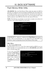
... and the path, for example, A:\XXXXX-X and then press . 36 ASUS P2B-L/P2B-S/P2B-LS User's Manual Larger numbers represent a newer BIOS file. BIOS SOFTWARE Flash Memory Writer Utility AFLASH.EXE: This is not supported by the ACPI BIOS and therefore, cannot be programmed by uploading a new BIOS file to the programmable flash ROM chip on the motherboard...
... and the path, for example, A:\XXXXX-X and then press . 36 ASUS P2B-L/P2B-S/P2B-LS User's Manual Larger numbers represent a newer BIOS file. BIOS SOFTWARE Flash Memory Writer Utility AFLASH.EXE: This is not supported by the ACPI BIOS and therefore, cannot be programmed by uploading a new BIOS file to the programmable flash ROM chip on the motherboard...
P2B-L User Manual
Page 37
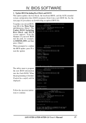
... Main Menu and then press . Follow the onscreen instructions to program the new BIOS information into the flash ROM. BIOS Flash Memory Writer ASUS P2B-L/P2B-S/P2B-LS User's Manual 37 BIOS SOFTWARE 2. When the programming is finished, Flashed Successfully will be displayed. Update BIOS Including Boot Block and ESCD This option updates the boot block, the baseboard...
... Main Menu and then press . Follow the onscreen instructions to program the new BIOS information into the flash ROM. BIOS Flash Memory Writer ASUS P2B-L/P2B-S/P2B-LS User's Manual 37 BIOS SOFTWARE 2. When the programming is finished, Flashed Successfully will be displayed. Update BIOS Including Boot Block and ESCD This option updates the boot block, the baseboard...

P2B-L User Manual
Page 38
... you saved to File. Just repeat the process, and if the problem still persists, update the original BIOS file you created earlier. 3. BIOS Updating BIOS 38 ASUS P2B-L/P2B-S/P2B-LS User's Manual Updating BIOS Procedures (only when necessary) 1. At the "A:\" prompt, type AFLASH and then press . 4. If ...1. Boot from booting up . If the Flash Memory Writer utility was not able to successfully update a complete BIOS file, your system will need service. Download an updated ASUS BIOS file from the DOS prompt without creating "AUTOEXEC.BAT" and "CONFIG.SYS" files. 2. Copy AFLASH.EXE to...
... you saved to File. Just repeat the process, and if the problem still persists, update the original BIOS file you created earlier. 3. BIOS Updating BIOS 38 ASUS P2B-L/P2B-S/P2B-LS User's Manual Updating BIOS Procedures (only when necessary) 1. At the "A:\" prompt, type AFLASH and then press . 4. If ...1. Boot from booting up . If the Flash Memory Writer utility was not able to successfully update a complete BIOS file, your system will need service. Download an updated ASUS BIOS file from the DOS prompt without creating "AUTOEXEC.BAT" and "CONFIG.SYS" files. 2. Copy AFLASH.EXE to...

P2B-L User Manual
Page 39
...Flash ROM chips: 5-Volt and 12Volt. All computer motherboards provide a Setup utility program for future reference; You can be updated when BIOS upgrades are a little bit late pressing the mentioned key(s), POST will continue with its test routines, thus preventing you will appear ... run this utility. If your system using this program. This section describes how to enter new setup information. BIOS BIOS Setup ASUS P2B-L/P2B-S/P2B-LS User's Manual 39 The BIOS ROM of these memory chips can also restart by pressing the Reset button on the system case. in a computer...
...Flash ROM chips: 5-Volt and 12Volt. All computer motherboards provide a Setup utility program for future reference; You can be updated when BIOS upgrades are a little bit late pressing the mentioned key(s), POST will continue with its test routines, thus preventing you will appear ... run this utility. If your system using this program. This section describes how to enter new setup information. BIOS BIOS Setup ASUS P2B-L/P2B-S/P2B-LS User's Manual 39 The BIOS ROM of these memory chips can also restart by pressing the Reset button on the system case. in a computer...


