User Guide
Page 3
... 2-4 2.5 Removing the storage drive assembly 2-4 2.6 Installing a CPU 2-5 2.6.1 Removing the CPU fan and heatsink assembly ... 2-5 2.6.2 CPU installation 2-6 2.6.3 Reinstalling the CPU fan and heatsink assembly 2-8 2.7 Installing memory modules 2-9 2.7.1 Overview 2-9 2.7.2 Memory configurations 2-9 2.7.3 Qualified Vendor List 2-10 2.7.4 Installing a DIMM 2-10 2.7.5 Removing a DIMM 2-13 2.8 Installing PCI cards 2-13 2.8.1 PCI slots 2-13 2.8.2 PCI card installation 2-13 2.8.3 Configuring an...
... 2-4 2.5 Removing the storage drive assembly 2-4 2.6 Installing a CPU 2-5 2.6.1 Removing the CPU fan and heatsink assembly ... 2-5 2.6.2 CPU installation 2-6 2.6.3 Reinstalling the CPU fan and heatsink assembly 2-8 2.7 Installing memory modules 2-9 2.7.1 Overview 2-9 2.7.2 Memory configurations 2-9 2.7.3 Qualified Vendor List 2-10 2.7.4 Installing a DIMM 2-10 2.7.5 Removing a DIMM 2-13 2.8 Installing PCI cards 2-13 2.8.1 PCI slots 2-13 2.8.2 PCI card installation 2-13 2.8.3 Configuring an...
User Guide
Page 5
First SATA Master ....5-11 5.3.4 HDD SMART Monitoring 5-12 5.3.5 Installed Memory 5-12 5.3.6 Usable Memory 5-12 5.4 Advanced Menu 5-13 5.4.1 CPU configuration 5-13 5.4.2 Chipset configuration 5-14 5.4.3 PCIPnP 5-15 5.4.4 Onboard device ... Security 5-27 5.7 Exit menu 5-29 v Table of contents Chapter 5: BIOS setup 5.1 Managing and updating your BIOS 5-2 5.1.1 ASUS EZ Flash utility 5-2 5.1.2 Recovering the BIOS with CrashFree BIOS 2 ..... 5-3 5.1.3 ASUS Update 5-5 5.2 BIOS Setup program 5-7 5.2.1 BIOS menu bar 5-8 5.2.2 Legend bar 5-8 5.3 Main Menu 5-10 5.3.1 System Time ...
First SATA Master ....5-11 5.3.4 HDD SMART Monitoring 5-12 5.3.5 Installed Memory 5-12 5.3.6 Usable Memory 5-12 5.4 Advanced Menu 5-13 5.4.1 CPU configuration 5-13 5.4.2 Chipset configuration 5-14 5.4.3 PCIPnP 5-15 5.4.4 Onboard device ... Security 5-27 5.7 Exit menu 5-29 v Table of contents Chapter 5: BIOS setup 5.1 Managing and updating your BIOS 5-2 5.1.1 ASUS EZ Flash utility 5-2 5.1.2 Recovering the BIOS with CrashFree BIOS 2 ..... 5-3 5.1.3 ASUS Update 5-5 5.2 BIOS Setup program 5-7 5.2.1 BIOS menu bar 5-8 5.2.2 Legend bar 5-8 5.3 Main Menu 5-10 5.3.1 System Time ...
User Guide
Page 12
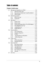
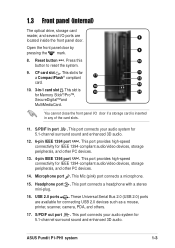
... 800MHz front side bus (FSB), and up when data is a union of the optical drive. 5 3. Power LED . Eject button . Foot stand. The ASUS book size barebone system is being read 6 from or written to eject the loading tray of power, design, and performance built on . 6. Front panel I/O ... stand allows you eject the loading tray. 2. HDD LED . 1.1 Welcome! Optical drive bay cover. 1 This door opens when you to 2GB system memory. This LED lights up to place the system in -1 card reader, CF card reader, USB, S/PDIF, and IEEE 1394 interfaces. Power button .
... 800MHz front side bus (FSB), and up when data is a union of the optical drive. 5 3. Power LED . Eject button . Foot stand. The ASUS book size barebone system is being read 6 from or written to eject the loading tray of power, design, and performance built on . 6. Front panel I/O ... stand allows you eject the loading tray. 2. HDD LED . 1.1 Welcome! Optical drive bay cover. 1 This door opens when you to 2GB system memory. This LED lights up to place the system in -1 card reader, CF card reader, USB, S/PDIF, and IEEE 1394 interfaces. Power button .
User Guide
Page 13
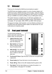
... card is 15 14 for Memory Stick®/Pro™, SecureDigital™and MultiMediaCard. This port provides high-speed connectivity for IEEE 1394-compliant audio/video devices, storage peripherals, and other PC devices. 14. Press this 10 button to reset the system. 9. This slot is inserted in -1 card slot . ASUS Pundit P1-PH1 system 1-3
... card is 15 14 for Memory Stick®/Pro™, SecureDigital™and MultiMediaCard. This port provides high-speed connectivity for IEEE 1394-compliant audio/video devices, storage peripherals, and other PC devices. 14. Press this 10 button to reset the system. 9. This slot is inserted in -1 card slot . ASUS Pundit P1-PH1 system 1-3
User Guide
Page 18
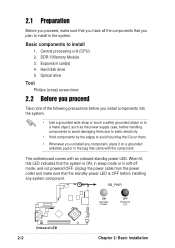
... ON, in sleep mode or in the bag that came with an onboard standby power LED. Basic components to install in the system. DDR II Memory Module 3. Hard disk drive 5. Optical drive Tool Phillips (cross) screw driver 2.2 Before you proceed Take note of the following precautions before you plan to install...
... ON, in sleep mode or in the bag that came with an onboard standby power LED. Basic components to install in the system. DDR II Memory Module 3. Hard disk drive 5. Optical drive Tool Phillips (cross) screw driver 2.2 Before you proceed Take note of the following precautions before you plan to install...
User Guide
Page 21
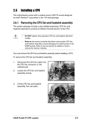
...comes with a surface mount LGA775 socket designed for details on the motherboard. 2. Lift the CPU fan and heatsink assembly, then set aside. ASUS Pundit P1-PH1 system 2-5 Refer to the next section for Intel® Pentium® 4 processor in the 775-land package. 2.6.1 Removing the CPU fan and heatsink... thermal solution to the CPU. • DO NOT replace the proprietary CPU fan and heatsink with other models. • Remove the memory modules first before installing a CPU. You must remove the CPU fan and heatsink assembly before removing the CPU fan and heatsink assembly to...
...comes with a surface mount LGA775 socket designed for details on the motherboard. 2. Lift the CPU fan and heatsink assembly, then set aside. ASUS Pundit P1-PH1 system 2-5 Refer to the next section for Intel® Pentium® 4 processor in the 775-land package. 2.6.1 Removing the CPU fan and heatsink... thermal solution to the CPU. • DO NOT replace the proprietary CPU fan and heatsink with other models. • Remove the memory modules first before installing a CPU. You must remove the CPU fan and heatsink assembly before removing the CPU fan and heatsink assembly to...
User Guide
Page 25
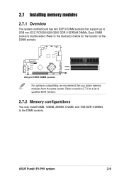
Refer to the DIMM sockets. Refer to section 2.7.3 for a list of qualified DDR vendors. 2.7.2 Memory configurations You may install 64MB, 128MB, 256MB, 512MB, and 1GB DDR II DIMMs to the illustration below for the location of the DIMM sockets. ® ... optimum compatibility, we recommend that support up to 2GB non-ECC PC5300/4200/3200 DDR II SDRAM DIMMs. Each DIMM socket is double-sided. 2.7 Installing memory modules 2.7.1 Overview The system motherboard has two DDR II DIMM sockets that you obtain memory modules from the same vendor. ASUS Pundit P1-PH1 system 2-9
Refer to the DIMM sockets. Refer to section 2.7.3 for a list of qualified DDR vendors. 2.7.2 Memory configurations You may install 64MB, 128MB, 256MB, 512MB, and 1GB DDR II DIMMs to the illustration below for the location of the DIMM sockets. ® ... optimum compatibility, we recommend that support up to 2GB non-ECC PC5300/4200/3200 DDR II SDRAM DIMMs. Each DIMM socket is double-sided. 2.7 Installing memory modules 2.7.1 Overview The system motherboard has two DDR II DIMM sockets that you obtain memory modules from the same vendor. ASUS Pundit P1-PH1 system 2-9

User Guide
Page 26
...pair of modules inserted into eithor the blue slots or the black slots as one module inserted in any slot as Single-channel memory configuration. Size Vendor Model CL 256MB SAMSUNG M378T3253FZ0-CE6 - 512MB SAMSUNG M378T6453FZ0-CE6 - 1024MB Kingston KVR667D2N5/1G - 512MB Hynix HYMP564U64AP8...3S V V HYB18T512800AF3S V V HYB18T512800AF3S V V E5108AE-GE-E VV - 2.7.3 Qualified Vendor List The following table lists the DDR II 667 memory modules that have been tested and qualified for the latest QVL. 2-10 Chapter 2: Basic installation B* : Supports one pair of Dual-channel...
...pair of modules inserted into eithor the blue slots or the black slots as one module inserted in any slot as Single-channel memory configuration. Size Vendor Model CL 256MB SAMSUNG M378T3253FZ0-CE6 - 512MB SAMSUNG M378T6453FZ0-CE6 - 1024MB Kingston KVR667D2N5/1G - 512MB Hynix HYMP564U64AP8...3S V V HYB18T512800AF3S V V HYB18T512800AF3S V V E5108AE-GE-E VV - 2.7.3 Qualified Vendor List The following table lists the DDR II 667 memory modules that have been tested and qualified for the latest QVL. 2-10 Chapter 2: Basic installation B* : Supports one pair of Dual-channel...
User Guide
Page 28
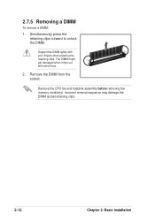
Remove the DIMM from the socket. The DIMM might get damaged when it flips out with your fingers when pressing the retaining clips. Simultaneously press the retaining clips outward to unlock the DIMM. Support the DIMM lightly with extra force. 2. Remove the CPU fan and heatsink assembly before removing the memory module(s). Incorrect removal sequence may damage the DIMM socket retaining clips. 2-12 Chapter 2: Basic installation 2.7.5 Removing a DIMM To remove a DIMM: 1.
Remove the DIMM from the socket. The DIMM might get damaged when it flips out with your fingers when pressing the retaining clips. Simultaneously press the retaining clips outward to unlock the DIMM. Support the DIMM lightly with extra force. 2. Remove the CPU fan and heatsink assembly before removing the memory module(s). Incorrect removal sequence may damage the DIMM socket retaining clips. 2-12 Chapter 2: Basic installation 2.7.5 Removing a DIMM To remove a DIMM: 1.
User Guide
Page 45
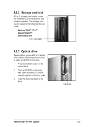
... CD/DVD is properly seated on the drive tray. Tray locks ASUS Pundit P1-PH1 system 3-3 Push the drive tray back to the drive. 1. Press the EJECT button of the optical drive. 2. The storage card reader supports the following storage cards: • Memory Stick® / Pro™ • Secure Digital™ • MultimediaCard 3-in... drive. Place a CD/DVD on the tray locks. 3. 3.3.2 Storage card slot A 3-in-1 storage card reader comes pre-installed in -1 card reader 3.3.3 Optical drive If your ASUS book size barebone system.
... CD/DVD is properly seated on the drive tray. Tray locks ASUS Pundit P1-PH1 system 3-3 Push the drive tray back to the drive. 1. Press the EJECT button of the optical drive. 2. The storage card reader supports the following storage cards: • Memory Stick® / Pro™ • Secure Digital™ • MultimediaCard 3-in... drive. Place a CD/DVD on the tray locks. 3. 3.3.2 Storage card slot A 3-in-1 storage card reader comes pre-installed in -1 card reader 3.3.3 Optical drive If your ASUS book size barebone system.
User Guide
Page 53
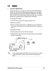
... position. Hold down the key during the boot process and enter BIOS setup to pins 1-2. 4. Removing the cap will cause system boot failure. ASUS Pundit P1-PH1 system 4-3 The RAM data in CMOS. Reinstall the battery. 5. Plug the power cord and turn ON the computer. 6. Move the jumper cap...system setup information such as system passwords, is powered by erasing the CMOS RTC RAM data. Remove the battery. 3. You can clear the CMOS memory of date, time, and system setup parameters by the onboard button cell battery. To erase the RTC RAM: 1. CLRTC 12 23 NORMAL CLEAR...
... position. Hold down the key during the boot process and enter BIOS setup to pins 1-2. 4. Removing the cap will cause system boot failure. ASUS Pundit P1-PH1 system 4-3 The RAM data in CMOS. Reinstall the battery. 5. Plug the power cord and turn ON the computer. 6. Move the jumper cap...system setup information such as system passwords, is powered by erasing the CMOS RTC RAM data. Remove the battery. 3. You can clear the CMOS memory of date, time, and system setup parameters by the onboard button cell battery. To erase the RTC RAM: 1. CLRTC 12 23 NORMAL CLEAR...
User Guide
Page 68
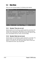
... 2084). System Time System Date 09:40:12 Wed., Nov 30 2005 Primary IDE Master [HDS7288080PLAT20] Primary IDE Slave [ASUS CD-S360] First SATA Master [None] HDD SMART Monitoring [Disabled] Installed Memory Usable Memory 512 MB 447 MB Select Menu Item Specific Help Change the internal clock. 5.3.1 System Time [xx:xx:xx] Sets...
... 2084). System Time System Date 09:40:12 Wed., Nov 30 2005 Primary IDE Master [HDS7288080PLAT20] Primary IDE Slave [ASUS CD-S360] First SATA Master [None] HDD SMART Monitoring [Disabled] Installed Memory Usable Memory 512 MB 447 MB Select Menu Item Specific Help Change the internal clock. 5.3.1 System Time [xx:xx:xx] Sets...
User Guide
Page 70
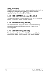
... by the system during the boot process. This item is not user-configurable. 5.3.6 Usable Memory [xxx MB] This field automatically displays the Usable Memory detected by the system during the boot process. Configuration options: [Disabled] [Auto] 5.3.4 HDD SMART Monitoring [Disabled] This option allows you to suppress Ultra DMA capability. ...
... by the system during the boot process. This item is not user-configurable. 5.3.6 Usable Memory [xxx MB] This field automatically displays the Usable Memory detected by the system during the boot process. Configuration options: [Disabled] [Auto] 5.3.4 HDD SMART Monitoring [Disabled] This option allows you to suppress Ultra DMA capability. ...
User Guide
Page 72
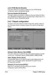
...BIOS forces the XD feature flag to always return to your location. Chipset Current MRC Version Current DRAM Frequency Onboard Video Memory Size Video Display Devices Onboard TV-out Format Memory Hole System BIOS Cacheable 6.4 533 MHz [64MB] [Auto] [NTSC] [Disabled] [Disabled] Select Menu Item Specific... MaxVal [Disable] This option allows you intend to use . Select an item then press to select the type of the onboard graphics controller memory use . Configuration options: [32MB] [64MB] [128MB] [256MB] Video Display Device [Auto] This parameter allows you to display a pop-up...
...BIOS forces the XD feature flag to always return to your location. Chipset Current MRC Version Current DRAM Frequency Onboard Video Memory Size Video Display Devices Onboard TV-out Format Memory Hole System BIOS Cacheable 6.4 533 MHz [64MB] [Auto] [NTSC] [Disabled] [Disabled] Select Menu Item Specific... MaxVal [Disable] This option allows you intend to use . Select an item then press to select the type of the onboard graphics controller memory use . Configuration options: [32MB] [64MB] [128MB] [256MB] Video Display Device [Auto] This parameter allows you to display a pop-up...
User Guide
Page 73
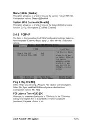
... you to enter the value in this menu show the PCIPnP configuration settings. ASUS Pundit P1-PH1 system 5-15 Configuration options: [Disabled] [Enabled] System BIOS Cacheable [Disable] This option allows you to enable or disable the Memory Hole at 15M-16M. Memory Hole [Disable] This option allows you to enable or disable the System BIOS...
... you to enter the value in this menu show the PCIPnP configuration settings. ASUS Pundit P1-PH1 system 5-15 Configuration options: [Disabled] [Enabled] System BIOS Cacheable [Disable] This option allows you to enable or disable the Memory Hole at 15M-16M. Memory Hole [Disable] This option allows you to enable or disable the System BIOS...