User Guide
Page 4
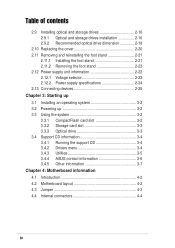
... operating system 3-2 3.2 Powering up 3-2 3.3 Using the system 3-2 3.3.1 CompactFlash card slot 3-2 3.3.2 Storage card slot 3-3 3.3.3 Optical drive 3-3 3.4 Support CD information 3-4 3.4.1 Running the support CD 3-4 3.4.2 Drivers menu 3-4 3.4.3 Utilities 3-5 3.4.4 ASUS contact information 3-6 3.4.5 Other information 3-7 Chapter 4: Motherboard information 4.1 Introduction 4-2 4.2 Motherboard layout 4-2 4.3 Jumper 4-3 4.4 Internal connectors 4-4 iv
... operating system 3-2 3.2 Powering up 3-2 3.3 Using the system 3-2 3.3.1 CompactFlash card slot 3-2 3.3.2 Storage card slot 3-3 3.3.3 Optical drive 3-3 3.4 Support CD information 3-4 3.4.1 Running the support CD 3-4 3.4.2 Drivers menu 3-4 3.4.3 Utilities 3-5 3.4.4 ASUS contact information 3-6 3.4.5 Other information 3-7 Chapter 4: Motherboard information 4.1 Introduction 4-2 4.2 Motherboard layout 4-2 4.3 Jumper 4-3 4.4 Internal connectors 4-4 iv
User Guide
Page 8
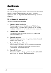
.... 4. Chapter 5: BIOS setup This chapter tells how to install components in the system. 3. Chapter 1: System introduction This chapter gives a general description of personal computers. Chapter 4: Motherboard information This chapter gives information about the ASUS Book size barebone system. How this guide Audience This guide provides general information and installation instructions about the...
.... 4. Chapter 5: BIOS setup This chapter tells how to install components in the system. 3. Chapter 1: System introduction This chapter gives a general description of personal computers. Chapter 4: Motherboard information This chapter gives information about the ASUS Book size barebone system. How this guide Audience This guide provides general information and installation instructions about the...
User Guide
Page 10
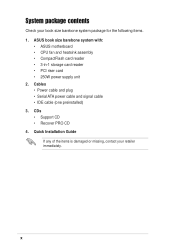
Quick Installation Guide If any of the items is damaged or missing, contact your book size barebone system package for the following items. 1. ASUS book size barebone system with: • ASUS motherboard • CPU fan and heatsink assembly • CompactFlash card reader • 3-in-1 storage card reader • PCI riser card • 250W power...
Quick Installation Guide If any of the items is damaged or missing, contact your book size barebone system package for the following items. 1. ASUS book size barebone system with: • ASUS motherboard • CPU fan and heatsink assembly • CompactFlash card reader • 3-in-1 storage card reader • PCI riser card • 250W power...
User Guide
Page 12
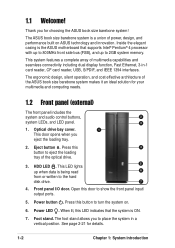
...you to show the front panel input/ output ports. 5. Thank you eject the loading tray. 2. Inside the elegant casing is the ASUS motherboard that the system is ON. 7. The ergonomic design, silent operation, and cost effective architecture of multimedia capabilities and seamless connectivity including dual... to the hard disk drive. 7 4. Power LED . This system features a complete array of the ASUS book size barebone system makes it an ideal solution for choosing the ASUS book size barebone system! Press this LED indicates that supports Intel® Pentium® 4 processor with ...
...you to show the front panel input/ output ports. 5. Thank you eject the loading tray. 2. Inside the elegant casing is the ASUS motherboard that the system is ON. 7. The ergonomic design, silent operation, and cost effective architecture of multimedia capabilities and seamless connectivity including dual... to the hard disk drive. 7 4. Power LED . This system features a complete array of the ASUS book size barebone system makes it an ideal solution for choosing the ASUS book size barebone system! Press this LED indicates that supports Intel® Pentium® 4 processor with ...
User Guide
Page 16
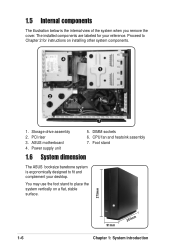
... and heatsink assembly 7. Storage drive assembly 2. You may use the foot stand to fit and complement your reference. PCI riser 3. ASUS motherboard 4. DIMM sockets 6. Power supply unit 5. Foot stand 1.6 System dimension The ASUS booksize barebone system is the internal view of the system when you remove the cover. 1.5 Internal components The illustration below...
... and heatsink assembly 7. Storage drive assembly 2. You may use the foot stand to fit and complement your reference. PCI riser 3. ASUS motherboard 4. DIMM sockets 6. Power supply unit 5. Foot stand 1.6 System dimension The ASUS booksize barebone system is the internal view of the system when you remove the cover. 1.5 Internal components The illustration below...
User Guide
Page 18
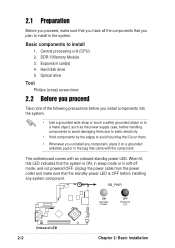
... avoid damaging them . • Whenever you uninstall any system component. Expansion card(s) 4. Basic components to install in soft-off mode, and not powered OFF. The motherboard comes with the component.
... avoid damaging them . • Whenever you uninstall any system component. Expansion card(s) 4. Basic components to install in soft-off mode, and not powered OFF. The motherboard comes with the component.
User Guide
Page 21
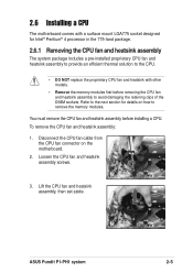
... CPU fan connector on how to avoid damaging the retaining clips of the DIMM sockets. Lift the CPU fan and heatsink assembly, then set aside. ASUS Pundit P1-PH1 system 2-5 Loosen the CPU fan and heatsink assembly screws. 3. Refer to the next section for Intel® Pentium® 4 processor in the ... to the CPU. • DO NOT replace the proprietary CPU fan and heatsink with a surface mount LGA775 socket designed for details on the motherboard. 2. You must remove the CPU fan and heatsink assembly before removing the CPU fan and heatsink assembly to remove the memory modules.
... CPU fan connector on how to avoid damaging the retaining clips of the DIMM sockets. Lift the CPU fan and heatsink assembly, then set aside. ASUS Pundit P1-PH1 system 2-5 Loosen the CPU fan and heatsink assembly screws. 3. Refer to the next section for Intel® Pentium® 4 processor in the ... to the CPU. • DO NOT replace the proprietary CPU fan and heatsink with a surface mount LGA775 socket designed for details on the motherboard. 2. You must remove the CPU fan and heatsink assembly before removing the CPU fan and heatsink assembly to remove the memory modules.
User Guide
Page 22
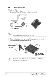
Press the load lever with your thumb (A) and move it is on your left (B) until it to the socket pins, do not remove the PnP cap unless you are installing a CPU. 2-6 Chapter 2: Basic installation Retention tab A Load lever PnP Cap B This side of the socket box should face you and the load lever is released from the retention tab. To prevent damage to the left . 2. 2.6.2 CPU installation To install the CPU: 1. Locate the 775-pin CPU socket on the motherboard. ® CPU Socket 775 Before installing the CPU, make sure that the socket box is facing towards you .
Press the load lever with your thumb (A) and move it is on your left (B) until it to the socket pins, do not remove the PnP cap unless you are installing a CPU. 2-6 Chapter 2: Basic installation Retention tab A Load lever PnP Cap B This side of the socket box should face you and the load lever is released from the retention tab. To prevent damage to the left . 2. 2.6.2 CPU installation To install the CPU: 1. Locate the 775-pin CPU socket on the motherboard. ® CPU Socket 775 Before installing the CPU, make sure that the socket box is facing towards you .
User Guide
Page 24
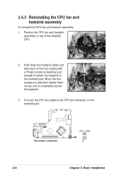
Connect the CPU fan cable to the motherboard. Hold down the heatsink lightly and twist each of the four screws with a Philips (cross) screwdriver just enough to attach the heatsink to the CPU ...: 1. When the four screws are attached, tighten them one by one to completely secure the heatsink. 3. Position the CPU fan and heatsink assembly on the motherboard. ® Fan power connector CPU_FAN Rotation +12V GND 2-8 Chapter 2: Basic installation
Connect the CPU fan cable to the motherboard. Hold down the heatsink lightly and twist each of the four screws with a Philips (cross) screwdriver just enough to attach the heatsink to the CPU ...: 1. When the four screws are attached, tighten them one by one to completely secure the heatsink. 3. Position the CPU fan and heatsink assembly on the motherboard. ® Fan power connector CPU_FAN Rotation +12V GND 2-8 Chapter 2: Basic installation
User Guide
Page 25
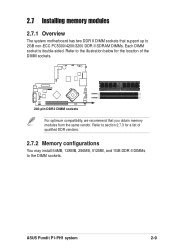
... a list of the DIMM sockets. ® DIMMA1 DIMMB1 240-pin DDR2 DIMM sockets For optimum compatibility, we recommend that support up to the DIMM sockets. ASUS Pundit P1-PH1 system 2-9 2.7 Installing memory modules 2.7.1 Overview The system motherboard has two DDR II DIMM sockets that you obtain memory modules from the same vendor.
... a list of the DIMM sockets. ® DIMMA1 DIMMB1 240-pin DDR2 DIMM sockets For optimum compatibility, we recommend that support up to the DIMM sockets. ASUS Pundit P1-PH1 system 2-9 2.7 Installing memory modules 2.7.1 Overview The system motherboard has two DDR II DIMM sockets that you obtain memory modules from the same vendor.

User Guide
Page 26
...blue slots or the black slots as one module inserted in any slot as Single-channel memory configuration. Obtain DDR II DIMMs only from ASUS qualified vendors. Size Vendor Model CL 256MB SAMSUNG M378T3253FZ0-CE6 - 512MB SAMSUNG M378T6453FZ0-CE6 - 1024MB Kingston KVR667D2N5/1G - 512MB Hynix HYMP564U64AP8...Infineon Infineon Infineon ELPIDA - VV E2508AB-GE-E VV A* : Supports one pair of Dual-channel memory configuration. Visit the ASUS website (www.asus.com) for use with this motherboard. ELPIDA SS/DS SS DS DS SS DS SS DS SS SS SS SS DS SS DS SS DIMM support Component ...
...blue slots or the black slots as one module inserted in any slot as Single-channel memory configuration. Obtain DDR II DIMMs only from ASUS qualified vendors. Size Vendor Model CL 256MB SAMSUNG M378T3253FZ0-CE6 - 512MB SAMSUNG M378T6453FZ0-CE6 - 1024MB Kingston KVR667D2N5/1G - 512MB Hynix HYMP564U64AP8...Infineon Infineon Infineon ELPIDA - VV E2508AB-GE-E VV A* : Supports one pair of Dual-channel memory configuration. Visit the ASUS website (www.asus.com) for use with this motherboard. ELPIDA SS/DS SS DS DS SS DS SS DS SS SS SS SS DS SS DS SS DIMM support Component ...
User Guide
Page 27
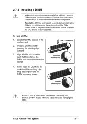
...Locked retaining clip A DDR II DIMM is properly seated. DO NOT force a DIMM into the socket until the retaining clips snap back in the motherboard. 2. Refer to the previous section for details on the socket such that it fits in only one direction. To install a DIMM: 1. Align...so may cause severe damage to both the motherboard and the components. • Reinstall the CPU fan and heatsink assembly before adding or removing DIMMs or other system components. Unlock a DIMM socket by pressing the retaining clips outward. 3. ASUS Pundit P1-PH1 system 2-11 Locate the DIMM sockets in...
...Locked retaining clip A DDR II DIMM is properly seated. DO NOT force a DIMM into the socket until the retaining clips snap back in the motherboard. 2. Refer to the previous section for details on the socket such that it fits in only one direction. To install a DIMM: 1. Align...so may cause severe damage to both the motherboard and the components. • Reinstall the CPU fan and heatsink assembly before adding or removing DIMMs or other system components. Unlock a DIMM socket by pressing the retaining clips outward. 3. ASUS Pundit P1-PH1 system 2-11 Locate the DIMM sockets in...
User Guide
Page 29
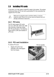
...you may need to install PCI cards to unplug the power cord before adding or removing expansion cards. PCI riser assembly ASUS Pundit P1-PH1 system 2-13 The system motherboard has one PCI slot with PCI specifications. Make sure to the system. 2.8 Installing PCI cards In the future, ...you physical injury and damage motherboard components. 2.8.1 PCI slots The PCI slots support PCI cards such as a LAN card, SCSI card, USB card,...
...you may need to install PCI cards to unplug the power cord before adding or removing expansion cards. PCI riser assembly ASUS Pundit P1-PH1 system 2-13 The system motherboard has one PCI slot with PCI specifications. Make sure to the system. 2.8 Installing PCI cards In the future, ...you physical injury and damage motherboard components. 2.8.1 PCI slots The PCI slots support PCI cards such as a LAN card, SCSI card, USB card,...
User Guide
Page 31
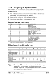
... will arise between the two PCI groups, making the system unstable and the card inoperable. ASUS Pundit P1-PH1 system 2-15 Turn on BIOS setup. 2. Assign an IRQ to the tables below. 3. Onboard 1394 controller -- -- -- -- -- See Chapter 5 for this motherboard A B C D E PCI slot 1 used -- -- -- Standard interrupt assignments IRQ Priority Standard Function 0 1 System Timer 1 2 Keyboard Controller...
... will arise between the two PCI groups, making the system unstable and the card inoperable. ASUS Pundit P1-PH1 system 2-15 Turn on BIOS setup. 2. Assign an IRQ to the tables below. 3. Onboard 1394 controller -- -- -- -- -- See Chapter 5 for this motherboard A B C D E PCI slot 1 used -- -- -- Standard interrupt assignments IRQ Priority Standard Function 0 1 System Timer 1 2 Keyboard Controller...
User Guide
Page 33
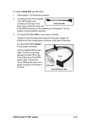
... power connector: Use the supplied SATA power cable. Connect a 4-pin plug (female) from the power supply unit (PSU) to the SATA connector on the motherboard. See page 4-7 for the location of the previous section. 2. Follow steps 1-3 of the Serial ATA connector. 3. Connect one end of the supplied 7-pin... (female) power plug from the PSU to the power connector at the back of the drive. 15-pin 4-pin (male) Serial ATA power cable ASUS Pundit P1-PH1 system 2-17 Connect the 15-pin SATA power plug to the 4-pin (male) plug of the drive. To install a Serial ATA hard disk drive...
... power connector: Use the supplied SATA power cable. Connect a 4-pin plug (female) from the power supply unit (PSU) to the SATA connector on the motherboard. See page 4-7 for the location of the previous section. 2. Follow steps 1-3 of the Serial ATA connector. 3. Connect one end of the supplied 7-pin... (female) power plug from the PSU to the power connector at the back of the drive. 15-pin 4-pin (male) Serial ATA power cable ASUS Pundit P1-PH1 system 2-17 Connect the 15-pin SATA power plug to the 4-pin (male) plug of the drive. To install a Serial ATA hard disk drive...
User Guide
Page 44
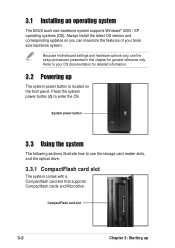
3.1 Installing an operating system The ASUS book size barebone system supports Windows® 2000 / XP operating systems (OS). Because motherboard settings and hardware options vary, use the storage card reader slots, and the optical drive. 3.3.1 CompactFlash card slot The system comes with a Compactflash card slot ...
3.1 Installing an operating system The ASUS book size barebone system supports Windows® 2000 / XP operating systems (OS). Because motherboard settings and hardware options vary, use the storage card reader slots, and the optical drive. 3.3.1 CompactFlash card slot The system comes with a Compactflash card slot ...
User Guide
Page 47
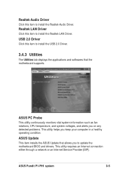
... alerts you on any detected problems. This utility helps you to update the motherboard BIOS and drivers. USB 2.0 Driver Click this item to install the Realtek Audio Driver. ASUS Update This item installs the ASUS Update that the motherboard supports. ASUS Pundit P1-PH1 system 3-5 Realtek Audio Driver Click this item to install the USB 2.0 Driver. 3.4.3 Utilities...
... alerts you on any detected problems. This utility helps you to update the motherboard BIOS and drivers. USB 2.0 Driver Click this item to install the Realtek Audio Driver. ASUS Update This item installs the ASUS Update that the motherboard supports. ASUS Pundit P1-PH1 system 3-5 Realtek Audio Driver Click this item to install the USB 2.0 Driver. 3.4.3 Utilities...

User Guide
Page 49
Motherboard info Displays the general specifications of the support CD. Browse this CD Displays the support CD contents in graphical format. ASUS Pundit P1-PH1 system 3-7 Click an icon to display the specified information. 3.4.5 Other information The icons on the top right side of the screen give additional information on the motherboard and the contents of the motherboard.
Motherboard info Displays the general specifications of the support CD. Browse this CD Displays the support CD contents in graphical format. ASUS Pundit P1-PH1 system 3-7 Click an icon to display the specified information. 3.4.5 Other information The icons on the top right side of the screen give additional information on the motherboard and the contents of the motherboard.

User Guide
Page 51
Motherboard info Chapter 4 This chapter gives information about the motherboard that comes with the system. This chapter includes the motherboard layout, jumper settings, and connector locations.
Motherboard info Chapter 4 This chapter gives information about the motherboard that comes with the system. This chapter includes the motherboard layout, jumper settings, and connector locations.

User Guide
Page 52
4.1 Introduction The ASUS motherboard comes already installed in the ASUS book size barebone system. This chapter provides technical information about the motherboard for future upgrades or system reconfiguration. 4.2 Motherboard layout PMC Flash CR2032 3V Lithium Cell CMOS Power CLRTC USB34 SB_PWR PANEL BUZZER RSTCON SMSC USB2227 CF_CON PRI_IDE VIA VT6307 SATA1 ATI SB450 3IN1_CON ... DDR2 DIMMA1 (64 bit,240-pin module) DDR2 DIMMB1 (64 bit,240-pin module) LGA775 ATX12V SPDIF_IN SPDIF_OUT IE1394_1 PWRSW IE1394_2 USB12 FP_AUDIO CPU_FAN 4-2 Chapter 4: Motherboard info
4.1 Introduction The ASUS motherboard comes already installed in the ASUS book size barebone system. This chapter provides technical information about the motherboard for future upgrades or system reconfiguration. 4.2 Motherboard layout PMC Flash CR2032 3V Lithium Cell CMOS Power CLRTC USB34 SB_PWR PANEL BUZZER RSTCON SMSC USB2227 CF_CON PRI_IDE VIA VT6307 SATA1 ATI SB450 3IN1_CON ... DDR2 DIMMA1 (64 bit,240-pin module) DDR2 DIMMB1 (64 bit,240-pin module) LGA775 ATX12V SPDIF_IN SPDIF_OUT IE1394_1 PWRSW IE1394_2 USB12 FP_AUDIO CPU_FAN 4-2 Chapter 4: Motherboard info