User Guide
Page 4
... 2-24 2.13 Connecting devices 2-25 Chapter 3: Starting up 3.1 Installing an operating system 3-2 3.2 Powering up 3-2 3.3 Using the system 3-2 3.3.1 CompactFlash card slot 3-2 3.3.2 Storage card slot 3-3 3.3.3 Optical drive 3-3 3.4 Support CD information 3-4 3.4.1 Running the support CD 3-4 3.4.2 Drivers menu 3-4 3.4.3 Utilities 3-5 3.4.4 ASUS contact information 3-6 3.4.5 Other information 3-7 Chapter 4: Motherboard information 4.1 Introduction 4-2 4.2 Motherboard layout 4-2 4.3 Jumper 4-3 4.4 Internal connectors 4-4 iv
... 2-24 2.13 Connecting devices 2-25 Chapter 3: Starting up 3.1 Installing an operating system 3-2 3.2 Powering up 3-2 3.3 Using the system 3-2 3.3.1 CompactFlash card slot 3-2 3.3.2 Storage card slot 3-3 3.3.3 Optical drive 3-3 3.4 Support CD information 3-4 3.4.1 Running the support CD 3-4 3.4.2 Drivers menu 3-4 3.4.3 Utilities 3-5 3.4.4 ASUS contact information 3-6 3.4.5 Other information 3-7 Chapter 4: Motherboard information 4.1 Introduction 4-2 4.2 Motherboard layout 4-2 4.3 Jumper 4-3 4.4 Internal connectors 4-4 iv
User Guide
Page 8
... this guide Audience This guide provides general information and installation instructions about the motherboard that comes with hardware knowledge of the ASUS Book size barebone system. Chapter 1: System introduction This chapter gives a general description of personal computers. This chapter includes...describes the BIOS parameters. Chapter 3: Starting up This chapter helps you power up the system and install drivers and utilities from the support CD. 4. Chapter 5: BIOS setup This chapter tells how to install components in the system. 3. viii This guide is organized ...
... this guide Audience This guide provides general information and installation instructions about the motherboard that comes with hardware knowledge of the ASUS Book size barebone system. Chapter 1: System introduction This chapter gives a general description of personal computers. This chapter includes...describes the BIOS parameters. Chapter 3: Starting up This chapter helps you power up the system and install drivers and utilities from the support CD. 4. Chapter 5: BIOS setup This chapter tells how to install components in the system. 3. viii This guide is organized ...
User Guide
Page 10
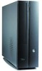
... barebone system with: • ASUS motherboard • CPU fan and heatsink assembly • CompactFlash card reader • 3-in-1 storage card reader • PCI riser card • 250W power supply unit 2. CDs • Support CD • Recover PRO CD 4. System package contents Check your retailer immediately. Cables • Power cable and plug •...
... barebone system with: • ASUS motherboard • CPU fan and heatsink assembly • CompactFlash card reader • 3-in-1 storage card reader • PCI riser card • 250W power supply unit 2. CDs • Support CD • Recover PRO CD 4. System package contents Check your retailer immediately. Cables • Power cable and plug •...
User Guide
Page 12
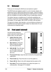
...dual display function, Fast Ethernet, 3-in a vertical position. Optical drive bay cover. 1 This door opens when you for choosing the ASUS book size barebone system! See page 2-21 for your multimedia and computing needs. 1.2 Front panel (external) The front panel includes ... on . 6. The ergonomic design, silent operation, and cost effective architecture of the optical drive. 5 3. Eject button . Press this LED indicates that supports Intel® Pentium® 4 processor with up to show the front panel input/ output ports. 5. When lit, this 4 button to the hard ...
...dual display function, Fast Ethernet, 3-in a vertical position. Optical drive bay cover. 1 This door opens when you for choosing the ASUS book size barebone system! See page 2-21 for your multimedia and computing needs. 1.2 Front panel (external) The front panel includes ... on . 6. The ergonomic design, silent operation, and cost effective architecture of the optical drive. 5 3. Eject button . Press this LED indicates that supports Intel® Pentium® 4 processor with up to show the front panel input/ output ports. 5. When lit, this 4 button to the hard ...
User Guide
Page 20
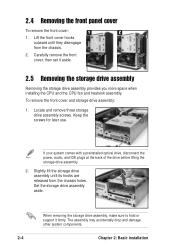
Locate and remove three storage drive assembly screws. When removing the storage drive assembly, make sure to hold or support it aside. 2.5 Removing the storage drive assembly Removing the storage drive assembly provides you more space when installing the CPU and the CPU fan and ...
Locate and remove three storage drive assembly screws. When removing the storage drive assembly, make sure to hold or support it aside. 2.5 Removing the storage drive assembly Removing the storage drive assembly provides you more space when installing the CPU and the CPU fan and ...
User Guide
Page 25
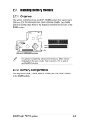
... motherboard has two DDR II DIMM sockets that support up to the illustration below for a list of the DIMM sockets. ® DIMMA1 DIMMB1 240-pin DDR2 DIMM sockets For optimum compatibility, we recommend that you obtain memory modules from the same vendor. ASUS Pundit P1-PH1 system 2-9 Refer to 2GB non-ECC PC5300/4200...
... motherboard has two DDR II DIMM sockets that support up to the illustration below for a list of the DIMM sockets. ® DIMMA1 DIMMB1 240-pin DDR2 DIMM sockets For optimum compatibility, we recommend that you obtain memory modules from the same vendor. ASUS Pundit P1-PH1 system 2-9 Refer to 2GB non-ECC PC5300/4200...

User Guide
Page 26
... pair of Dual-channel memory configuration. ELPIDA SS/DS SS DS DS SS DS SS DS SS SS SS SS DS SS DS SS DIMM support Component A* B* K4T56083QF-ZCE6 V V K4T56083QF-ZCE6 V V E5108AE-GE-E VV HY5PS12821AFP-Y5 V V HY5PS12821AFP-Y4 V V HY5PS12821AFP-Y4 V V 4VB41D9CZM VV 4SB42D9CZM VV...Brand SAMSUNG SAMSUNG Kingston Hynix Hynix Hynix MICRON MICRON MICRON Infineon Infineon Infineon ELPIDA - Obtain DDR II DIMMs only from ASUS qualified vendors. B* : Supports one pair of modules inserted into eithor the blue slots or the black slots as Single-channel memory configuration. 2.7.3...
... pair of Dual-channel memory configuration. ELPIDA SS/DS SS DS DS SS DS SS DS SS SS SS SS DS SS DS SS DIMM support Component A* B* K4T56083QF-ZCE6 V V K4T56083QF-ZCE6 V V E5108AE-GE-E VV HY5PS12821AFP-Y5 V V HY5PS12821AFP-Y4 V V HY5PS12821AFP-Y4 V V 4VB41D9CZM VV 4SB42D9CZM VV...Brand SAMSUNG SAMSUNG Kingston Hynix Hynix Hynix MICRON MICRON MICRON Infineon Infineon Infineon ELPIDA - Obtain DDR II DIMMs only from ASUS qualified vendors. B* : Supports one pair of modules inserted into eithor the blue slots or the black slots as Single-channel memory configuration. 2.7.3...
User Guide
Page 28
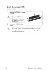
Support the DIMM lightly with extra force. 2. Incorrect removal sequence may damage the DIMM socket retaining clips. 2-12 Chapter 2: Basic installation Remove the DIMM from the socket. Remove the CPU fan and heatsink assembly before removing the memory module(s). 2.7.5 Removing a DIMM To remove a DIMM: 1. The DIMM might get damaged when it flips out with your fingers when pressing the retaining clips. Simultaneously press the retaining clips outward to unlock the DIMM.
Support the DIMM lightly with extra force. 2. Incorrect removal sequence may damage the DIMM socket retaining clips. 2-12 Chapter 2: Basic installation Remove the DIMM from the socket. Remove the CPU fan and heatsink assembly before removing the memory module(s). 2.7.5 Removing a DIMM To remove a DIMM: 1. The DIMM might get damaged when it flips out with your fingers when pressing the retaining clips. Simultaneously press the retaining clips outward to unlock the DIMM.
User Guide
Page 29
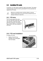
... following figure shows a LAN card installed on a PCI slot. 2.8.2 PCI card installation To install a PCI card: 1. PCI riser assembly ASUS Pundit P1-PH1 system 2-13 Make sure to the system. Failure to do so may need to install PCI cards to unplug the power cord before adding ... cause you physical injury and damage motherboard components. 2.8.1 PCI slots The PCI slots support PCI cards such as a LAN card, SCSI card, USB card, and other cards that comply with a preinstalled PCI riser assembly that supports two PCI cards. Slightly lift the PCI riser assembly until it disengages from the...
... following figure shows a LAN card installed on a PCI slot. 2.8.2 PCI card installation To install a PCI card: 1. PCI riser assembly ASUS Pundit P1-PH1 system 2-13 Make sure to the system. Failure to do so may need to install PCI cards to unplug the power cord before adding ... cause you physical injury and damage motherboard components. 2.8.1 PCI slots The PCI slots support PCI cards such as a LAN card, SCSI card, USB card, and other cards that comply with a preinstalled PCI riser assembly that supports two PCI cards. Slightly lift the PCI riser assembly until it disengages from the...
User Guide
Page 31
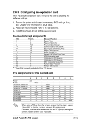
...installing the expansion card, configure the card by adjusting the software settings. 1. Turn on shared slots, ensure that the drivers support "Share IRQ" or that the cards do not need IRQ assignments. shared -- Onboard LAN -- -- -- -- shared -- ... slot 1 used -- -- -- shared -- -- -- shared -- Onboard USB 2.0 controller -- -- -- shared -- -- -- Onboard 1394 controller -- -- -- -- -- Onboard SATA1 -- -- -- -- -- F G H -- -- -- -- -- -- -- -- -- -- -- -- -- -- -- -- -- -- -- -- -- -- -- -- ASUS Pundit P1-PH1 system 2-15
...installing the expansion card, configure the card by adjusting the software settings. 1. Turn on shared slots, ensure that the drivers support "Share IRQ" or that the cards do not need IRQ assignments. shared -- Onboard LAN -- -- -- -- shared -- ... slot 1 used -- -- -- shared -- -- -- shared -- Onboard USB 2.0 controller -- -- -- shared -- -- -- Onboard 1394 controller -- -- -- -- -- Onboard SATA1 -- -- -- -- -- F G H -- -- -- -- -- -- -- -- -- -- -- -- -- -- -- -- -- -- -- -- -- -- -- -- ASUS Pundit P1-PH1 system 2-15
User Guide
Page 32
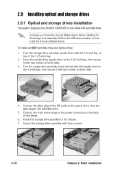
... device. Turn the storage drive assembly upside down to the hard disk drive. 5. 2.9 Installing optical and storage drives 2.9.1 Optical and storage drives installation The system supports one UltraATA 100/66 IDE or one Serial ATA hard disk drive. Turn the storage drive assembly, insert the hard disk drive upside down with...
... device. Turn the storage drive assembly upside down to the hard disk drive. 5. 2.9 Installing optical and storage drives 2.9.1 Optical and storage drives installation The system supports one UltraATA 100/66 IDE or one Serial ATA hard disk drive. Turn the storage drive assembly, insert the hard disk drive upside down with...
User Guide
Page 43
Chapter 3 This chapter helps you to install drivers and utilities from the support CD. This part also provides information on how to power up Starting up and use the system for the first time.
Chapter 3 This chapter helps you to install drivers and utilities from the support CD. This part also provides information on how to power up Starting up and use the system for the first time.
User Guide
Page 44
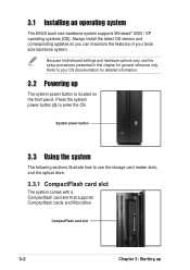
... reference only. CompactFlash card slot 3-2 Chapter 3: Starting up The system power button is located on the front panel. 3.1 Installing an operating system The ASUS book size barebone system supports Windows® 2000 / XP operating systems (OS). Because motherboard settings and hardware options vary, use the storage card reader slots, and the optical...
... reference only. CompactFlash card slot 3-2 Chapter 3: Starting up The system power button is located on the front panel. 3.1 Installing an operating system The ASUS book size barebone system supports Windows® 2000 / XP operating systems (OS). Because motherboard settings and hardware options vary, use the storage card reader slots, and the optical...
User Guide
Page 45
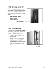
Push the drive tray back to the drive. 1. Tray locks ASUS Pundit P1-PH1 system 3-3 Place a CD/DVD on the tray locks. 3. Press the EJECT button of the optical drive. 2. The storage card reader supports the following storage cards: • Memory Stick® / Pro™ • Secure Digital™ • MultimediaCard 3-in your system comes.../DVD is properly seated on the drive tray. 3.3.2 Storage card slot A 3-in-1 storage card reader comes pre-installed in -1 card reader 3.3.3 Optical drive If your ASUS book size barebone system.
Push the drive tray back to the drive. 1. Tray locks ASUS Pundit P1-PH1 system 3-3 Place a CD/DVD on the tray locks. 3. Press the EJECT button of the optical drive. 2. The storage card reader supports the following storage cards: • Memory Stick® / Pro™ • Secure Digital™ • MultimediaCard 3-in your system comes.../DVD is properly seated on the drive tray. 3.3.2 Storage card slot A 3-in-1 storage card reader comes pre-installed in -1 card reader 3.3.3 Optical drive If your ASUS book size barebone system.

User Guide
Page 46
...to run the CD. 3.4.2 Drivers menu The drivers menu shows the available device drivers if the system detects installed devices. 3.4 Support CD information The support CD that came with the system contains useful software and several utility drivers that enhance the system features. • Screen display ...and driver options may not be the same for updates. 3.4.1 Running the support CD To begin using the support CD, place the CD in your computer. Visit the ASUS website for other information If Autorun is enabled in your optical drive.
...to run the CD. 3.4.2 Drivers menu The drivers menu shows the available device drivers if the system detects installed devices. 3.4 Support CD information The support CD that came with the system contains useful software and several utility drivers that enhance the system features. • Screen display ...and driver options may not be the same for updates. 3.4.1 Running the support CD To begin using the support CD, place the CD in your computer. Visit the ASUS website for other information If Autorun is enabled in your optical drive.
User Guide
Page 47
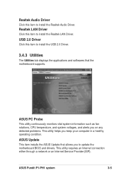
ASUS Pundit P1-PH1 system 3-5 Realtek Audio Driver Click this item to install the USB 2.0 Driver. 3.4.3 Utilities The Utilities tab displays the applications and softwares that allows you keep your computer in a healthy operating condition. ASUS PC Probe This utility continuously monitors vital system information such...Internet Service Provider (ISP). USB 2.0 Driver Click this item to update the motherboard BIOS and drivers. ASUS Update This item installs the ASUS Update that the motherboard supports. Realtek LAN Driver Click this item to install the Realtek Audio Driver.
ASUS Pundit P1-PH1 system 3-5 Realtek Audio Driver Click this item to install the USB 2.0 Driver. 3.4.3 Utilities The Utilities tab displays the applications and softwares that allows you keep your computer in a healthy operating condition. ASUS PC Probe This utility continuously monitors vital system information such...Internet Service Provider (ISP). USB 2.0 Driver Click this item to update the motherboard BIOS and drivers. ASUS Update This item installs the ASUS Update that the motherboard supports. Realtek LAN Driver Click this item to install the Realtek Audio Driver.

User Guide
Page 49
ASUS Pundit P1-PH1 system 3-7 Motherboard info Displays the general specifications of the support CD. Browse this CD Displays the support CD contents in graphical format. Click an icon to display the specified information. 3.4.5 Other information The icons on the top right side of the screen give additional information on the motherboard and the contents of the motherboard.
ASUS Pundit P1-PH1 system 3-7 Motherboard info Displays the general specifications of the support CD. Browse this CD Displays the support CD contents in graphical format. Click an icon to display the specified information. 3.4.5 Other information The icons on the top right side of the screen give additional information on the motherboard and the contents of the motherboard.

User Guide
Page 50
Technical support form Displays the ASUS Technical Support Request Form that you have to fill out when requesting technical support. Filelist Displays the contents of the support CD and a brief description of each in text format. 3-8 Chapter 3: Starting up
Technical support form Displays the ASUS Technical Support Request Form that you have to fill out when requesting technical support. Filelist Displays the contents of the support CD and a brief description of each in text format. 3-8 Chapter 3: Starting up

User Guide
Page 54
USB connector (10-1 pin USB34) If the rear panel USB 2.0 ports are inadequate, a USB header is connected to the ASUS proprietary daughtercard that supports the rear panel audio I/O, S-Video, and composite video ports. ® D33005 ® TVOUT_REARAUDIO connectors 4-4 Chapter 4: Motherboard info You may connect the cable of the rear ...
USB connector (10-1 pin USB34) If the rear panel USB 2.0 ports are inadequate, a USB header is connected to the ASUS proprietary daughtercard that supports the rear panel audio I/O, S-Video, and composite video ports. ® D33005 ® TVOUT_REARAUDIO connectors 4-4 Chapter 4: Motherboard info You may connect the cable of the rear ...
User Guide
Page 55
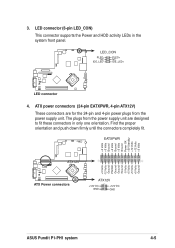
LED connector (6-pin LED_CON) This connector supports the Power and HDD activity LEDs in only one orientation. LED_CON PLEDNC IDE_LED- ATX power connectors (24-pin EATXPWR, 4-pin ATX12V) These connectors are for ... +3 Volts -12 Volts Ground PSON# Ground Ground Ground -5 Volts +5 Volts +5 Volts +5 Volts Ground ATX12V ® ATX Power connectors ATX12V +12V DC GND +12V DC GND ASUS Pundit P1-PH1 system 4-5 Find the proper orientation and push down firmly until the connectors completely fit. 3.
LED connector (6-pin LED_CON) This connector supports the Power and HDD activity LEDs in only one orientation. LED_CON PLEDNC IDE_LED- ATX power connectors (24-pin EATXPWR, 4-pin ATX12V) These connectors are for ... +3 Volts -12 Volts Ground PSON# Ground Ground Ground -5 Volts +5 Volts +5 Volts +5 Volts Ground ATX12V ® ATX Power connectors ATX12V +12V DC GND +12V DC GND ASUS Pundit P1-PH1 system 4-5 Find the proper orientation and push down firmly until the connectors completely fit. 3.