P1-AH1 User''s Manual for English Edition
Page 3
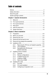
... 2-4 2.5 Removing the storage drive assembly 2-4 2.6 Installing a CPU 2-5 2.6.1 Removing the CPU fan and heatsink assembly ... 2-5 2.6.2 CPU installation 2-6 2.6.3 Reinstalling the CPU fan and heatsink assembly 2-8 2.7 Installing memory modules 2-9 2.7.1 Overview 2-9 2.7.2 Memory configurations 2-9 2.7.3 Qualified Vendors List 2-10 2.7.4 Installing a DIMM 2-13 2.7.5 Removing a DIMM 2-14 2.8 Installing PCI cards 2-15 2.8.1 PCI slots 2-15 2.8.2 PCI card installation 2-15 2.8.3 Configuring an...
... 2-4 2.5 Removing the storage drive assembly 2-4 2.6 Installing a CPU 2-5 2.6.1 Removing the CPU fan and heatsink assembly ... 2-5 2.6.2 CPU installation 2-6 2.6.3 Reinstalling the CPU fan and heatsink assembly 2-8 2.7 Installing memory modules 2-9 2.7.1 Overview 2-9 2.7.2 Memory configurations 2-9 2.7.3 Qualified Vendors List 2-10 2.7.4 Installing a DIMM 2-13 2.7.5 Removing a DIMM 2-14 2.8 Installing PCI cards 2-15 2.8.1 PCI slots 2-15 2.8.2 PCI card installation 2-15 2.8.3 Configuring an...
P1-AH1 User''s Manual for English Edition
Page 5
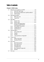
... Flash utility 5-2 5.1.2 Recovering the BIOS with CrashFree BIOS 2 ..... 5-3 5.1.3 ASUS Update 5-5 5.2 BIOS Setup program 5-7 5.2.1 BIOS menu bar 5-8 5.2.2 Legend bar 5-8 5.3 Main Menu 5-10 5.3.1 System Time 5-10 5.3.2 System Date 5-10 5.3.3 Primary IDE Master/Slave; First/Second SATA Master 5-11 5.3.4 HDD SMART Monitoring 5-12 5.3.5 Installed Memory 5-12 5.3.6 Usable Memory 5-12 5.4 Advanced Menu 5-13 5.4.1 CPU configuration 5-13 5.4.2 Chipset...
... Flash utility 5-2 5.1.2 Recovering the BIOS with CrashFree BIOS 2 ..... 5-3 5.1.3 ASUS Update 5-5 5.2 BIOS Setup program 5-7 5.2.1 BIOS menu bar 5-8 5.2.2 Legend bar 5-8 5.3 Main Menu 5-10 5.3.1 System Time 5-10 5.3.2 System Date 5-10 5.3.3 Primary IDE Master/Slave; First/Second SATA Master 5-11 5.3.4 HDD SMART Monitoring 5-12 5.3.5 Installed Memory 5-12 5.3.6 Usable Memory 5-12 5.4 Advanced Menu 5-13 5.4.1 CPU configuration 5-13 5.4.2 Chipset...
P1-AH1 User''s Manual for English Edition
Page 12
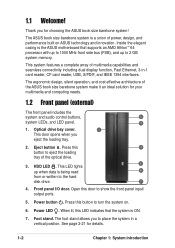
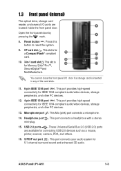
... is ON. 7. Eject button . HDD LED . Foot stand. Thank you eject the loading tray. 2. Open this button to 2 GB system memory. Power LED . The ASUS book size barebone system is being read 6 from or written to place the system in -1 card reader, CF card reader, USB, S/PDIF, ...cost effective architecture of power, design, and performance built on . 6. Optical drive bay cover. 1 This door opens when you for choosing the ASUS book size barebone system! Power button . Press this LED indicates that supports an AMD Athlon™ 64 processor with up to 1000 MHz front ...
... is ON. 7. Eject button . HDD LED . Foot stand. Thank you eject the loading tray. 2. Open this button to 2 GB system memory. Power LED . The ASUS book size barebone system is being read 6 from or written to place the system in -1 card reader, CF card reader, USB, S/PDIF, ...cost effective architecture of power, design, and performance built on . 6. Optical drive bay cover. 1 This door opens when you for choosing the ASUS book size barebone system! Power button . Press this LED indicates that supports an AMD Athlon™ 64 processor with up to 1000 MHz front ...
P1-AH1 User''s Manual for English Edition
Page 13
... audio/video devices, storage peripherals, and other PC devices. 13. This slot is 14 13 for 5.1-channel surround sound and enhanced 3D audio. Reset button . ASUS Pundit P1-AH1 1-3 This port connects a headphone with a stereo mini-plug. 15. 1.3 Front panel (internal) The optical drive, storage card reader, and several I /O door if a storage card...; compliant 16 11 card. 15 12 10. 3-in any of the card slots. 11. 6-pin IEEE 1394 port . This port connects your audio system for Memory Stick®/Pro™, SecureDigital™and MultiMediaCard. CF card slot .
... audio/video devices, storage peripherals, and other PC devices. 13. This slot is 14 13 for 5.1-channel surround sound and enhanced 3D audio. Reset button . ASUS Pundit P1-AH1 1-3 This port connects a headphone with a stereo mini-plug. 15. 1.3 Front panel (internal) The optical drive, storage card reader, and several I /O door if a storage card...; compliant 16 11 card. 15 12 10. 3-in any of the card slots. 11. 6-pin IEEE 1394 port . This port connects your audio system for Memory Stick®/Pro™, SecureDigital™and MultiMediaCard. CF card slot .
P1-AH1 User''s Manual for English Edition
Page 18
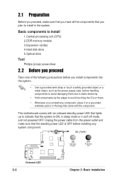
... in the system. SB_PWR1 ON OFF Standby Powered ® Power Off Onboard LED 2-2 Chapter 2: Basic installation Basic components to install 1.Central processing unit (CPU) 2.DDR memory module 3.Expansion card(s) 4.Hard disk drive 5.Optical drive Tool Phillips (cross) screw driver 2.2 Before you proceed Take note of the following precautions before you install...
... in the system. SB_PWR1 ON OFF Standby Powered ® Power Off Onboard LED 2-2 Chapter 2: Basic installation Basic components to install 1.Central processing unit (CPU) 2.DDR memory module 3.Expansion card(s) 4.Hard disk drive 5.Optical drive Tool Phillips (cross) screw driver 2.2 Before you proceed Take note of the following precautions before you install...
P1-AH1 User''s Manual for English Edition
Page 25
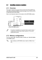
When installing one DDR DIMM module, install into DIMM_A1 slot only. ASUS Pundit P1-AH1 2-9 Refer to the DIMM sockets. 2.7 Installing memory modules 2.7.1 Overview The system motherboard comes with two Double Data Rate (DDR) Dual Inline Memory Modules (DIMM) sockets that support up to 2 GB non-ECC PC5300/4200/3200 DDR DIMMs. Refer to the illustration...
When installing one DDR DIMM module, install into DIMM_A1 slot only. ASUS Pundit P1-AH1 2-9 Refer to the DIMM sockets. 2.7 Installing memory modules 2.7.1 Overview The system motherboard comes with two Double Data Rate (DDR) Dual Inline Memory Modules (DIMM) sockets that support up to 2 GB non-ECC PC5300/4200/3200 DDR DIMMs. Refer to the illustration...
P1-AH1 User''s Manual for English Edition
Page 26
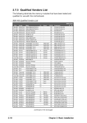
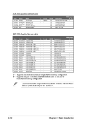
...; • M2G9I08A8ATT9F081CADT • • M2G9J16A8ATT9F081CADT • MDYVD6F4G2880B1E0H • (continued on the next page) 2-10 Chapter 2: Basic installation 2.7.3 Qualified Vendors List The following table lists the memory modules that have been tested and qualified for use with this motherboard. Brand SS/DS - SS - DS - SS - SS - DS SAMSUNG SS SAMSUNG DS SAMSUNG...
...; • M2G9I08A8ATT9F081CADT • • M2G9J16A8ATT9F081CADT • MDYVD6F4G2880B1E0H • (continued on the next page) 2-10 Chapter 2: Basic installation 2.7.3 Qualified Vendors List The following table lists the memory modules that have been tested and qualified for use with this motherboard. Brand SS/DS - SS - DS - SS - SS - DS SAMSUNG SS SAMSUNG DS SAMSUNG...
P1-AH1 User''s Manual for English Edition
Page 28
Aeneon DS -- B* : Supports one pair of Dual-channel memory configuration. SS -- DS DIMM support Component A* B* AED660UD00-500C88X • SVM-DDR3200/256 SVM-DDR3200/512 •• PDC1G3200+XBLK M512-400-16B DDR 333 Qualified ...-6K - 1024 MB NANYA NT5DS64M8CS-6K - 512 MB MOSEL V58C2256804SAT6 - 256 MB Aeneon AED83T600 - Brand - Visit the ASUS website (www.asus.com) for the latest QVL. 2-12 Chapter 2: Basic installation Obtain DDR DIMMs only from ASUS qualified vendors. DDR 400 Qualified Vendors List Size Vendor 512 MB Aeneon 256 MB SimpleTech 512 MB...
Aeneon DS -- B* : Supports one pair of Dual-channel memory configuration. SS -- DS DIMM support Component A* B* AED660UD00-500C88X • SVM-DDR3200/256 SVM-DDR3200/512 •• PDC1G3200+XBLK M512-400-16B DDR 333 Qualified ...-6K - 1024 MB NANYA NT5DS64M8CS-6K - 512 MB MOSEL V58C2256804SAT6 - 256 MB Aeneon AED83T600 - Brand - Visit the ASUS website (www.asus.com) for the latest QVL. 2-12 Chapter 2: Basic installation Obtain DDR DIMMs only from ASUS qualified vendors. DDR 400 Qualified Vendors List Size Vendor 512 MB Aeneon 256 MB SimpleTech 512 MB...

P1-AH1 User''s Manual for English Edition
Page 30
Support the DIMM lightly with extra force. 2. The DIMM might get damaged when it flips out with your fingers when pressing the retaining clips. Simultaneously press the retaining clips outward to unlock the DIMM. Remove the DIMM from the socket. 2.7.5 Removing a DIMM To remove a DIMM: 1. Unlocked retaining clip DDR DIMM notch Remove the CPU fan and heatsink assembly before removing the memory module(s). Incorrect removal sequence may damage the DIMM socket retaining clips. 2-14 Chapter 2: Basic installation
Support the DIMM lightly with extra force. 2. The DIMM might get damaged when it flips out with your fingers when pressing the retaining clips. Simultaneously press the retaining clips outward to unlock the DIMM. Remove the DIMM from the socket. 2.7.5 Removing a DIMM To remove a DIMM: 1. Unlocked retaining clip DDR DIMM notch Remove the CPU fan and heatsink assembly before removing the memory module(s). Incorrect removal sequence may damage the DIMM socket retaining clips. 2-14 Chapter 2: Basic installation
P1-AH1 User''s Manual for English Edition
Page 47
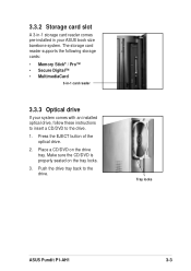
The storage card reader supports the following storage cards: • Memory Stick® / Pro™ • Secure Digital™ • MultimediaCard 3-in your system comes with an installed optical drive, follow these instructions to insert a CD/... properly seated on the drive tray. Press the EJECT button of the optical drive. 2. Tray locks ASUS Pundit P1-AH1 3-3 3.3.2 Storage card slot A 3-in-1 storage card reader comes pre-installed in -1 card reader 3.3.3 Optical drive If your ASUS book size barebone system. Push the drive tray back to the drive. 1. Place a CD/DVD on...
The storage card reader supports the following storage cards: • Memory Stick® / Pro™ • Secure Digital™ • MultimediaCard 3-in your system comes with an installed optical drive, follow these instructions to insert a CD/... properly seated on the drive tray. Press the EJECT button of the optical drive. 2. Tray locks ASUS Pundit P1-AH1 3-3 3.3.2 Storage card slot A 3-in-1 storage card reader comes pre-installed in -1 card reader 3.3.3 Optical drive If your ASUS book size barebone system. Push the drive tray back to the drive. 1. Place a CD/DVD on...
P1-AH1 User''s Manual for English Edition
Page 55
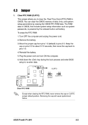
The RAM data in CMOS. Plug the power cord and turn ON the computer. 6. You can clear the CMOS memory of date, time, and system setup parameters by the onboard button cell battery. Turn OFF the computer and unplug the power cord. 2. Keep the cap ... information such as system passwords, is powered by erasing the CMOS RTC RAM data. Move the jumper cap from pins 1-2 (default) to re-enter data. ASUS Pundit P1-AH1 4-3 Clear RTC RAM (CLRTC) This jumper allows you to pins 1-2. 4. Remove the battery. 3. 4.3 Jumper 1. Removing the cap will cause system boot failure. Reinstall the...
The RAM data in CMOS. Plug the power cord and turn ON the computer. 6. You can clear the CMOS memory of date, time, and system setup parameters by the onboard button cell battery. Turn OFF the computer and unplug the power cord. 2. Keep the cap ... information such as system passwords, is powered by erasing the CMOS RTC RAM data. Move the jumper cap from pins 1-2 (default) to re-enter data. ASUS Pundit P1-AH1 4-3 Clear RTC RAM (CLRTC) This jumper allows you to pins 1-2. 4. Remove the battery. 3. 4.3 Jumper 1. Removing the cap will cause system boot failure. Reinstall the...
P1-AH1 User''s Manual for English Edition
Page 70
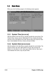
...:40:12 Fri, Dec 23 2005 Primary IDE Master Primary IDE Slave First SATA Master Second SATA Master HDD SMART Monitoring [HDS7288080PLAT20] [ASUS CD-S360] [None] [None] [Disabled] Installed Memory Usable Memory 512 MB 479 MB Select Menu Item Specific Help Change the internal clock. 5.3.1 System Time [xx:xx:xx] Sets the system...
...:40:12 Fri, Dec 23 2005 Primary IDE Master Primary IDE Slave First SATA Master Second SATA Master HDD SMART Monitoring [HDS7288080PLAT20] [ASUS CD-S360] [None] [None] [Disabled] Installed Memory Usable Memory 512 MB 479 MB Select Menu Item Specific Help Change the internal clock. 5.3.1 System Time [xx:xx:xx] Sets the system...
P1-AH1 User''s Manual for English Edition
Page 72
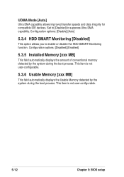
... MB] This field automatically displays the amount of conventional memory detected by the system during the boot process. Configuration options: [Disable] [Auto] 5.3.4 HDD SMART Monitoring [Disabled] This option allows you to suppress Ultra DMA ... DMA capability allows improved transfer speeds and data integrity for compatible IDE devices. This item is not user-configurable. 5.3.6 Usable Memory [xxx MB] This field automatically displays the Usable Memory detected by the system during the boot process. Set to [Disabled] to enable or disable the HDD SMART Monitoring function. This...
... MB] This field automatically displays the amount of conventional memory detected by the system during the boot process. Configuration options: [Disable] [Auto] 5.3.4 HDD SMART Monitoring [Disabled] This option allows you to suppress Ultra DMA ... DMA capability allows improved transfer speeds and data integrity for compatible IDE devices. This item is not user-configurable. 5.3.6 Usable Memory [xxx MB] This field automatically displays the Usable Memory detected by the system during the boot process. Set to [Disabled] to enable or disable the HDD SMART Monitoring function. This...
P1-AH1 User''s Manual for English Edition
Page 74
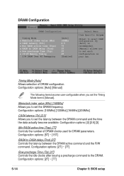
... Timing Mode x Memclock index value (Mhz) x CAS# latency (Tcl) x Min RAS# active time (Tras) x RAS# to CAS# delay (Trcd) x Row precharge Time (Trp) x 1T/2T Memory Timing S/W DRAM Over 4G Remapping [Auto] 166Mhz 2.5 7T 3T 3T 2T [Enabled] Select Menu Item Specific Help to set the latency between the DRAM active...
... Timing Mode x Memclock index value (Mhz) x CAS# latency (Tcl) x Min RAS# active time (Tras) x RAS# to CAS# delay (Trcd) x Row precharge Time (Trp) x 1T/2T Memory Timing S/W DRAM Over 4G Remapping [Auto] 166Mhz 2.5 7T 3T 3T 2T [Enabled] Select Menu Item Specific Help to set the latency between the DRAM active...
P1-AH1 User''s Manual for English Edition
Page 75
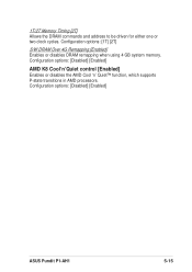
Configuration options: [Disabled] [Enabled] ASUS Pundit P1-AH1 5-15 Configuration options: [1T] [2T] S/W DRAM Over 4G Remapping [Enabled] Enables or disables DRAM remapping when using 4 GB system memory. Configuration options: [Disabled] [Enabled] AMD K8 Cool'n'Quiet control [Enabled] Enables or disables the AMD Cool 'n' Quiet™ function, which supports P-state transitions in AMD processors. 1T/2T Memory Timing [2T] Allows the DRAM commands and address to be driven for either one or two clock cycles.
Configuration options: [Disabled] [Enabled] ASUS Pundit P1-AH1 5-15 Configuration options: [1T] [2T] S/W DRAM Over 4G Remapping [Enabled] Enables or disables DRAM remapping when using 4 GB system memory. Configuration options: [Disabled] [Enabled] AMD K8 Cool'n'Quiet control [Enabled] Enables or disables the AMD Cool 'n' Quiet™ function, which supports P-state transitions in AMD processors. 1T/2T Memory Timing [2T] Allows the DRAM commands and address to be driven for either one or two clock cycles.
P1-AH1 User''s Manual for English Edition
Page 77
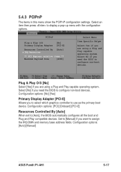
... system. Configuration options: [PCI] [Onboard] [PCI-E] Resources Controlled By [Auto] When set to configure non-boot devices. Configuration options: [Auto] [Manual] ASUS Pundit P1-AH1 5-17 Select [No] if you are using a Plug and Play capable operating system. Plug & Play O/S [No] Select [Yes] if you need the ...BIOS to assign the IRQ DMA and memory base address fields. Select No if you want to configure non-boot devices. Set to [...
... system. Configuration options: [PCI] [Onboard] [PCI-E] Resources Controlled By [Auto] When set to configure non-boot devices. Configuration options: [Auto] [Manual] ASUS Pundit P1-AH1 5-17 Select [No] if you are using a Plug and Play capable operating system. Plug & Play O/S [No] Select [Yes] if you need the ...BIOS to assign the IRQ DMA and memory base address fields. Select No if you want to configure non-boot devices. Set to [...

