User Manual
Page 5
... 5-24 5.2.7 Selecting the boot drive from a RAID set 5-25 5.2.8 Enabling the WriteCache 5-26 5.3 Global Array Manager 5-26 5.4 Adaptec SCSISelect(TM) Utility! (NCL-DE/SCSI model only 5-27 5.4.1 Configuring the SCSI controller 5-28 5.4.2 Enabling the HostRAID controller 5-28 5.4.3 Creating a RAID 0 set (Stripe 5-29 5.4.4 Creating a RAID 1 set (Mirror 5-33 5.4.5 Creating a RAID 10 set (Stripe+Mirror 5-36 5.4.6 Adding a spare...
... 5-24 5.2.7 Selecting the boot drive from a RAID set 5-25 5.2.8 Enabling the WriteCache 5-26 5.3 Global Array Manager 5-26 5.4 Adaptec SCSISelect(TM) Utility! (NCL-DE/SCSI model only 5-27 5.4.1 Configuring the SCSI controller 5-28 5.4.2 Enabling the HostRAID controller 5-28 5.4.3 Creating a RAID 0 set (Stripe 5-29 5.4.4 Creating a RAID 1 set (Mirror 5-33 5.4.5 Creating a RAID 10 set (Stripe+Mirror 5-36 5.4.6 Adding a spare...
User Manual
Page 6
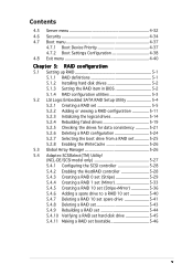
Contents Chapter 6: Driver installation 6.1 RAID driver installation 6-1 6.1.1 Creating a RAID driver disk 6-1 6.1.2 Installing the RAID controller driver 6-2 6.2 LAN driver installation 6-9 6.2.1 Windows® 2000/2003 Server 6-9 6.2.2 Red Hat® Enterprise ver. 3.0 6-11 6.3 VGA driver installation 6-13 6.3.1 Windows® 2000 ...15 6.4.1 Running the support CD 6-15 6.4.2 Drivers menu 6-15 6.4.3 Management Software menu 6-16 6.4.4 Utilities menu 6-16 6.4.5 Contact information 6-16 Appendix: Block diagrams A.1 NCL-DE/SCSI block diagram A-1 A.2 NCL-DE/1U block diagram A-2 vi
Contents Chapter 6: Driver installation 6.1 RAID driver installation 6-1 6.1.1 Creating a RAID driver disk 6-1 6.1.2 Installing the RAID controller driver 6-2 6.2 LAN driver installation 6-9 6.2.1 Windows® 2000/2003 Server 6-9 6.2.2 Red Hat® Enterprise ver. 3.0 6-11 6.3 VGA driver installation 6-13 6.3.1 Windows® 2000 ...15 6.4.1 Running the support CD 6-15 6.4.2 Drivers menu 6-15 6.4.3 Management Software menu 6-16 6.4.4 Utilities menu 6-16 6.4.5 Contact information 6-16 Appendix: Block diagrams A.1 NCL-DE/SCSI block diagram A-1 A.2 NCL-DE/1U block diagram A-2 vi
User Manual
Page 11
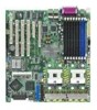
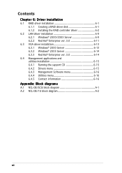
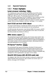
... link, PCI Express 1.0a) 1 x mini-PCI socket for ASUS® Server Management Board Intel® ICH5R Southbridge supports: - 4 x Ultra DMA 100/66/33 hard disk drives - 2 x SATA-150 with RAID 0, RAID 1 configuration (NCL-DE/SCSI model only) Adaptec® AIC-7902W PCI-X Dual U320 SCSI controller supports: - 2 x SCSI channels with PCI Express 1.0a specifications Intel® ICH5R...
... link, PCI Express 1.0a) 1 x mini-PCI socket for ASUS® Server Management Board Intel® ICH5R Southbridge supports: - 4 x Ultra DMA 100/66/33 hard disk drives - 2 x SATA-150 with RAID 0, RAID 1 configuration (NCL-DE/SCSI model only) Adaptec® AIC-7902W PCI-X Dual U320 SCSI controller supports: - 2 x SCSI channels with PCI Express 1.0a specifications Intel® ICH5R...
User Manual
Page 12
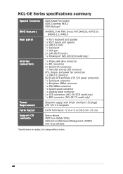
... Power Requirement Form Factor Support CD contents ASUS Smart Fan Control ASUS CrashFree BIOS 2 ASUS MyLogo2 AMI BIOS, 8 Mb FWH, Green, PnP, DMI2.0a, ACPI 2.0a SMBIOS 2.3, WfM2.0 1 x PS/2 keyboard port (purple) 1 x PS/2 mouse port (green) 2 x USB 2.0 ports 1 x Serial port 1 x VGA port 2 x LAN (RJ-45) ports 1 x Parallel port (NCL-DE/SCSI model only) 1 x Floppy disk drive connector...
... Power Requirement Form Factor Support CD contents ASUS Smart Fan Control ASUS CrashFree BIOS 2 ASUS MyLogo2 AMI BIOS, 8 Mb FWH, Green, PnP, DMI2.0a, ACPI 2.0a SMBIOS 2.3, WfM2.0 1 x PS/2 keyboard port (purple) 1 x PS/2 mouse port (green) 2 x USB 2.0 ports 1 x Serial port 1 x VGA port 2 x LAN (RJ-45) ports 1 x Parallel port (NCL-DE/SCSI model only) 1 x Floppy disk drive connector...
User Manual
Page 16
...bottlenecks with existing PCI or PCI-X specifications. See page 2-20 for details. Ultra320 SCSI feature (NCL-DE/SCSI model only) The Adaptec® AIC-7902 PCI-X SCSI controller is a new generation server class I/O controller hub that provides the interface for PCI 2.3. The ICH is onboard to support two ...68-pin Ultra320 SCSI connectors, each of which features data transfer rates of 400...
...bottlenecks with existing PCI or PCI-X specifications. See page 2-20 for details. Ultra320 SCSI feature (NCL-DE/SCSI model only) The Adaptec® AIC-7902 PCI-X SCSI controller is a new generation server class I/O controller hub that provides the interface for PCI 2.3. The ICH is onboard to support two ...68-pin Ultra320 SCSI connectors, each of which features data transfer rates of 400...
User Manual
Page 17
...controlled by the ASIC (integrated in the Winbond hardware monitor) to 150 MB/s data transfer rate. The ASIC monitors the voltage levels to Gigabit bandwidth. The ZCR capability provides a cost-effective high-performance and added reliability. The system fan rotations per minute (RPM) is monitored by the Intel® ICH5R. ASUS NCL-DE...cables with dual Gigabit LAN controllers and ports to a fast 480 Mbps on USB 1.1 to provide a total solution for critical components. See page 4-30 for details. Zero-Channel RAID (ZCR) solution (NCL-DE/SCSI model only) The motherboard ...
...controlled by the ASIC (integrated in the Winbond hardware monitor) to 150 MB/s data transfer rate. The ASIC monitors the voltage levels to Gigabit bandwidth. The ZCR capability provides a cost-effective high-performance and added reliability. The system fan rotations per minute (RPM) is monitored by the Intel® ICH5R. ASUS NCL-DE...cables with dual Gigabit LAN controllers and ports to a fast 480 Mbps on USB 1.1 to provide a total solution for critical components. See page 4-30 for details. Zero-Channel RAID (ZCR) solution (NCL-DE/SCSI model only) The motherboard ...
User Manual
Page 22
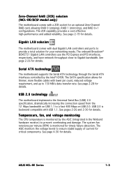
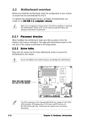
... chassis power cord before installing or removing the motherboard. These items are for NCL-DE/SCSI model only. NCL-DE Series ® Place this side towards the rear of the chassis The SCSI connectors, Zero Channel RAID (ZCR) slot, Adaptec® AIC-7902 SCSI controller, PCI Express slots, PCI-X slots, and PCI slot are grayed out in an...
... chassis power cord before installing or removing the motherboard. These items are for NCL-DE/SCSI model only. NCL-DE Series ® Place this side towards the rear of the chassis The SCSI connectors, Zero Channel RAID (ZCR) slot, Adaptec® AIC-7902 SCSI controller, PCI Express slots, PCI-X slots, and PCI slot are grayed out in an...
User Manual
Page 28
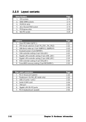
...Serial (COM1) port 5. Force BIOS recovery setting (3-pin RECOVERY1) Rear panel connectors 1. PS/2 mouse port (green) 2. Zero-Channel RAID socket 5. Gigabit LAN controller setting (3-pin LAN2_EN1) 8. SCSI controller setting (3-pin SCSI_EN1) 9. DDR2 DIMM sockets 3. Gigabit LAN (RJ-45) ports 7. PS/2 keyboard port (purple) Page 2-10 2-14 2-19 2-19 2-...23 2-24 2-24 2-25 2-25 Page 2-26 2-26 2-26 2-26 2-26 2-26 2-26 2-8 Chapter 2: Hardware information 2.2.5 Layout contents Slots/Sockets 1. VGA controller setting (3-pin VGA_EN1) 6. Parallel port (for NCL-DE model only) 3.
...Serial (COM1) port 5. Force BIOS recovery setting (3-pin RECOVERY1) Rear panel connectors 1. PS/2 mouse port (green) 2. Zero-Channel RAID socket 5. Gigabit LAN controller setting (3-pin LAN2_EN1) 8. SCSI controller setting (3-pin SCSI_EN1) 9. DDR2 DIMM sockets 3. Gigabit LAN (RJ-45) ports 7. PS/2 keyboard port (purple) Page 2-10 2-14 2-19 2-19 2-...23 2-24 2-24 2-25 2-25 Page 2-26 2-26 2-26 2-26 2-26 2-26 2-26 2-8 Chapter 2: Hardware information 2.2.5 Layout contents Slots/Sockets 1. VGA controller setting (3-pin VGA_EN1) 6. Parallel port (for NCL-DE model only) 3.
User Manual
Page 38
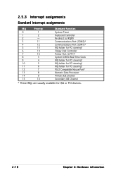
... 4 12 5 13 6 14 7 15 8 3 9 4 10 5 11 6 12 7 13 8 14 9 15 10 Standard Function System Timer Keyboard Controller Re-direct to IRQ#9 Communications Port (COM2)* Communications Port (COM1)* IRQ holder for PCI steering* Floppy Disk Controller Printer Port (LPT1)* System CMOS/Real Time Clock IRQ holder for PCI steering* IRQ holder for PCI...
... 4 12 5 13 6 14 7 15 8 3 9 4 10 5 11 6 12 7 13 8 14 9 15 10 Standard Function System Timer Keyboard Controller Re-direct to IRQ#9 Communications Port (COM2)* Communications Port (COM1)* IRQ holder for PCI steering* Floppy Disk Controller Printer Port (LPT1)* System CMOS/Real Time Clock IRQ holder for PCI steering* IRQ holder for PCI...
User Manual
Page 43
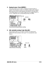
4. NCL-DE Series ® NCL-DE Series VGA setting VGA_EN1 1 2 Enable (Default) 2 3 Disable ASUS NCL-DE Series 2-23 Set this jumper to pins 2-3 (+5VSB) to enable or disable the onboard ATI® RAGE-XL PCI VGA controller. VGA controller setting (3-pin VGA_EN1) These jumpers allow you to wake up feature. Set to pins 1-2 to enable or disable the keyboard wake...
4. NCL-DE Series ® NCL-DE Series VGA setting VGA_EN1 1 2 Enable (Default) 2 3 Disable ASUS NCL-DE Series 2-23 Set this jumper to pins 2-3 (+5VSB) to enable or disable the onboard ATI® RAGE-XL PCI VGA controller. VGA controller setting (3-pin VGA_EN1) These jumpers allow you to wake up feature. Set to pins 1-2 to enable or disable the keyboard wake...
User Manual
Page 44
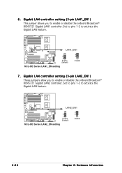
... enable or disable the onboard Broadcom® BCM5721 Gigabit LAN2 controller. Set to pins 1-2 to activate the Gigabit LAN feature. 6 . Set to pins 1-2 to activate the Gigabit LAN feature. NCL-DE Series ® LAN2_EN1 2 1 Enable (Default) 3 2 Disable NCL-DE Series LAN2_EN setting 2-24 Chapter 2: Hardware information NCL-DE Series ® LAN1_EN1 2 1 Enable (Default) NCL-DE Series LAN1_EN setting 3 2 Disable 7 .
... enable or disable the onboard Broadcom® BCM5721 Gigabit LAN2 controller. Set to pins 1-2 to activate the Gigabit LAN feature. 6 . Set to pins 1-2 to activate the Gigabit LAN feature. NCL-DE Series ® LAN2_EN1 2 1 Enable (Default) 3 2 Disable NCL-DE Series LAN2_EN setting 2-24 Chapter 2: Hardware information NCL-DE Series ® LAN1_EN1 2 1 Enable (Default) NCL-DE Series LAN1_EN setting 3 2 Disable 7 .

User Manual
Page 45
....ROM) and the AFUDOS.EXE utility. 2. Shut down the system. 5. NCL-DE Series ® RECOVERY1 12 23 Normal BIOS Recovery (Default) NCL-DE Series BIOS recovery setting ASUS NCL-DE Series 2-25 Set the jumper back to pins 2-3. 3. Force BIOS recovery ...disable the onboard Adaptec® AIC-7902W SCSI U320 controller. NCL-DE Series ® NCL-DE Series SCSI setting SCSI_EN1 12 23 Enable (Default) Disable 9 . SCSI controller setting (3-pin SCSI_EN1) (NCL-DE/SCSI model only) This jumper allows you to activate the SCSI feature, and support RAID configurations. To ...
....ROM) and the AFUDOS.EXE utility. 2. Shut down the system. 5. NCL-DE Series ® RECOVERY1 12 23 Normal BIOS Recovery (Default) NCL-DE Series BIOS recovery setting ASUS NCL-DE Series 2-25 Set the jumper back to pins 2-3. 3. Force BIOS recovery ...disable the onboard Adaptec® AIC-7902W SCSI U320 controller. NCL-DE Series ® NCL-DE Series SCSI setting SCSI_EN1 12 23 Enable (Default) Disable 9 . SCSI controller setting (3-pin SCSI_EN1) (NCL-DE/SCSI model only) This jumper allows you to activate the SCSI feature, and support RAID configurations. To ...
User Manual
Page 48
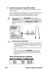
... ® GND RSATA_RXP2 RSATA_RXN2 GND RSATA_TXN2 RSATA_TXP2 GND GND RSATA_RXP1 RSATA_RXN1 GND RSATA_TXN1 RSATA_TXP1 GND SATA2 SATA1 NCL-DE Series SATA connectors Important notes on page 4-16 for Serial ATA hard disk drives. See section "4.3.5 IDE Configuration" on Serial ATA &#... If you can create a RAID 0 or RAID 1 configuration with the Adaptec® HostRAID™ Technology through the onboard Intel® ICH5R integrated RAID controller. 3 . The Serial ATA RAID feature (RAID 0/RAID 1) is available only if you can connect Serial ATA boot/data hard disk drives to these...
... ® GND RSATA_RXP2 RSATA_RXN2 GND RSATA_TXN2 RSATA_TXP2 GND GND RSATA_RXP1 RSATA_RXN1 GND RSATA_TXN1 RSATA_TXP1 GND SATA2 SATA1 NCL-DE Series SATA connectors Important notes on page 4-16 for Serial ATA hard disk drives. See section "4.3.5 IDE Configuration" on Serial ATA &#... If you can create a RAID 0 or RAID 1 configuration with the Adaptec® HostRAID™ Technology through the onboard Intel® ICH5R integrated RAID controller. 3 . The Serial ATA RAID feature (RAID 0/RAID 1) is available only if you can connect Serial ATA boot/data hard disk drives to these...
User Manual
Page 49
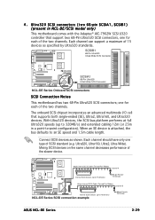
... device. With Ultra320 devices, the SCSI bus platform performs at full Ultra320 speeds (up to 15 devices) NCL-DE Series SCSI connection example 68-pin Female Terminator ASUS NCL-DE Series 2-29 Ultra320, Ultra160, Ultra2, Ultra-Wide). Mixing SCSI devices on the same channel decreases ...pin Female Terminator 68-pin Internal SCSI Cable (Twisted-Pair Ribbon) Channel B Internal SCSI Devices (up to 320MB/s) and extended cabling 12m (or 25m in NCL-DE/SCSI model only) This motherboard comes with the Adaptec® AIC-7902W SCSI U320 controller that supports both single-ended (...
... device. With Ultra320 devices, the SCSI bus platform performs at full Ultra320 speeds (up to 15 devices) NCL-DE Series SCSI connection example 68-pin Female Terminator ASUS NCL-DE Series 2-29 Ultra320, Ultra160, Ultra2, Ultra-Wide). Mixing SCSI devices on the same channel decreases ...pin Female Terminator 68-pin Internal SCSI Cable (Twisted-Pair Ribbon) Channel B Internal SCSI Devices (up to 320MB/s) and extended cabling 12m (or 25m in NCL-DE/SCSI model only) This motherboard comes with the Adaptec® AIC-7902W SCSI U320 controller that supports both single-ended (...
User Manual
Page 51
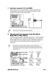
NCL-DE Series ® COM2 PIN 1 NCL-DE Series Serial port connectors The serial port module is for a serial (COM) port. Connect the fan cables to the fan connectors. Do not place jumper ... are not jumpers! CPU_FAN1 REAR_FAN2 CPU_FAN1 CPU_FAN2 NCL-DE Series ® GND FAN Power FAN Speed PWM Control PWM Control FAN Speed FAN Power GND REAR_FAN1 CPU_FAN2 FRNT_FAN1 FRNT_FAN2 NCL-DE Series Fan connectors REAR_FAN1 GND +12V Rotation FRNT_FAN1 GND +12V Rotation REAR_FAN2 Rotation +12V GND FRNT_FAN2 GND +12V Rotation ASUS NCL-DE Series 2-31 Serial port connector (10...
NCL-DE Series ® COM2 PIN 1 NCL-DE Series Serial port connectors The serial port module is for a serial (COM) port. Connect the fan cables to the fan connectors. Do not place jumper ... are not jumpers! CPU_FAN1 REAR_FAN2 CPU_FAN1 CPU_FAN2 NCL-DE Series ® GND FAN Power FAN Speed PWM Control PWM Control FAN Speed FAN Power GND REAR_FAN1 CPU_FAN2 FRNT_FAN1 FRNT_FAN2 NCL-DE Series Fan connectors REAR_FAN1 GND +12V Rotation FRNT_FAN1 GND +12V Rotation REAR_FAN2 Rotation +12V GND FRNT_FAN2 GND +12V Rotation ASUS NCL-DE Series 2-31 Serial port connector (10...
User Manual
Page 59
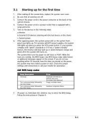
... press the ATX power button. After applying power, the system power LED on the screen. ASUS NCL-DE Series 3-1 While the tests are off. 3. Check the jumper settings and connections or call... continuous beeps followed by four short beeps Error Keyboard controller error Refresh Time error No master drive detected Floppy controller failure Hardware component failure 7. At power on self ...the power cord to the power connector at the back of the system chassis. 4. External SCSI devices (starting with the last device on . For systems withATX power supplies, the system ...
... press the ATX power button. After applying power, the system power LED on the screen. ASUS NCL-DE Series 3-1 While the tests are off. 3. Check the jumper settings and connections or call... continuous beeps followed by four short beeps Error Keyboard controller error Refresh Time error No master drive detected Floppy controller failure Hardware component failure 7. At power on self ...the power cord to the power connector at the back of the system chassis. 4. External SCSI devices (starting with the last device on . For systems withATX power supplies, the system ...
User Manual
Page 80
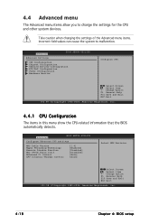
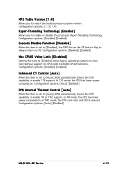
... devices. Advanced BIOS SETUP UTILITY Configure Advanced CPU settings MPS Table Version Hyper Threading Technology Execute Disable Function Max CPUID Value Limit Enhanced C1 Control CPU Internal Thermal Control [1.4] [Enabled] [Disabled] [Disabled] [Auto] [Auto] Select MPS Revision. Change Option F1 General Help F10 Save and Exit ESC Exit v02.58 (C)Copyright 1985...
... devices. Advanced BIOS SETUP UTILITY Configure Advanced CPU settings MPS Table Version Hyper Threading Technology Execute Disable Function Max CPUID Value Limit Enhanced C1 Control CPU Internal Thermal Control [1.4] [Enabled] [Disabled] [Disabled] [Auto] [Auto] Select MPS Revision. Change Option F1 General Help F10 Save and Exit ESC Exit v02.58 (C)Copyright 1985...
User Manual
Page 81
... always return to enable C1E support. In C1E mode, the CPU has lower power consumption. Configuration options: [Auto] [Disabled] ASUS NCL-DE Series 4-19 Configuration options: [Disabled] [Enabled] Execute Disable Function [Disabled] When this item to [Enabled] allows legacy operating ...mode, the CPU has lower power consumption. Configuration options: [Disabled] [Enabled] Enhanced C1 Control [Auto] When this item is reduced. Configuration options: [Auto] [Disabled] CPU Internal Thermal Control [Auto] When this item is set to [Auto], BIOS automatically checks the CPU capability ...
... always return to enable C1E support. In C1E mode, the CPU has lower power consumption. Configuration options: [Auto] [Disabled] ASUS NCL-DE Series 4-19 Configuration options: [Disabled] [Enabled] Execute Disable Function [Disabled] When this item to [Enabled] allows legacy operating ...mode, the CPU has lower power consumption. Configuration options: [Disabled] [Enabled] Enhanced C1 Control [Auto] When this item is reduced. Configuration options: [Auto] [Disabled] CPU Internal Thermal Control [Auto] When this item is set to [Auto], BIOS automatically checks the CPU capability ...
User Manual
Page 82
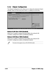
...2004, American Megatrends, Inc. Configuration options: [Disabled] [Enabled] The above item appears only on NCL-DE/SCSI model. 4-20 Chapter 4: BIOS setup Configuration options: [Disabled] [Enabled] Onboard SCSI Boot ROM [Enabled] Allows you to change the advanced chipset settings. Northbridge Configuration Onboard LAN Boot...enable or disable the option ROM in the onboard SCSI controller. Select an item then press to malfunction. Advanced Advanced Chipset Settings BIOS SETUP UTILITY WARNING: Setting wrong values in the onboard LAN controller. Onboard LAN Boot ROM [Enabled] Allows you to...
...2004, American Megatrends, Inc. Configuration options: [Disabled] [Enabled] The above item appears only on NCL-DE/SCSI model. 4-20 Chapter 4: BIOS setup Configuration options: [Disabled] [Enabled] Onboard SCSI Boot ROM [Enabled] Allows you to change the advanced chipset settings. Northbridge Configuration Onboard LAN Boot...enable or disable the option ROM in the onboard SCSI controller. Select an item then press to malfunction. Advanced Advanced Chipset Settings BIOS SETUP UTILITY WARNING: Setting wrong values in the onboard LAN controller. Onboard LAN Boot ROM [Enabled] Allows you to...
User Manual
Page 84
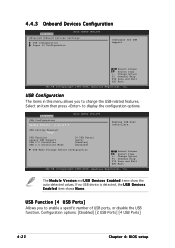
...U S B D e v i c e s E n a b l e d item shows N o n e. USB Devices Enabled: None USB Function Legacy USB Support USB 2.0 Controller USB 2.0 Controller Mode [4 USB Ports] [Auto] [Enabled] [HiSpeed] USB Mass Storage Device Configuration Select Screen Select Item +- Change Option F1 General Help F10 Save and Exit ESC.... Advanced USB Configuration Module Version - 2.23.2-5.3 BIOS SETUP UTILITY Enables USB host controllers. 4.4.3 Onboard Devices Configuration Advanced BIOS SETUP UTILITY Advanced Onboard Devices Settings USB Configuration Super IO Configuration Configure the USB...
...U S B D e v i c e s E n a b l e d item shows N o n e. USB Devices Enabled: None USB Function Legacy USB Support USB 2.0 Controller USB 2.0 Controller Mode [4 USB Ports] [Auto] [Enabled] [HiSpeed] USB Mass Storage Device Configuration Select Screen Select Item +- Change Option F1 General Help F10 Save and Exit ESC.... Advanced USB Configuration Module Version - 2.23.2-5.3 BIOS SETUP UTILITY Enables USB host controllers. 4.4.3 Onboard Devices Configuration Advanced BIOS SETUP UTILITY Advanced Onboard Devices Settings USB Configuration Super IO Configuration Configure the USB...