User Manual
Page 4
Contents 2.7 Connectors 2-26 2.7.1 Rear panel connectors 2-26 2.7.2 Internal connectors 2-27 Chapter 3: Powering up 3.1 Starting up for the first time 3-1 3.2 Turning off the computer 3-2 3.2.1 Using the OS shut down function 3-2 3.2.2 Using the dual function power switch 3-2 Chapter 4: BIOS setup 4.1 Managing and updating your BIOS 4-1 4.1.1 Creating a bootable floppy disk 4-1 4.1.2 AFUDOS utility 4-2 4.1.3 ASUS CrashFree BIOS 2 utility 4-5 4.1.4 ASUS Update utility...
Contents 2.7 Connectors 2-26 2.7.1 Rear panel connectors 2-26 2.7.2 Internal connectors 2-27 Chapter 3: Powering up 3.1 Starting up for the first time 3-1 3.2 Turning off the computer 3-2 3.2.1 Using the OS shut down function 3-2 3.2.2 Using the dual function power switch 3-2 Chapter 4: BIOS setup 4.1 Managing and updating your BIOS 4-1 4.1.1 Creating a bootable floppy disk 4-1 4.1.2 AFUDOS utility 4-2 4.1.3 ASUS CrashFree BIOS 2 utility 4-5 4.1.4 ASUS Update utility...
User Manual
Page 8
... power cables are connected. Contact a qualified service technician or your dealer immediately. • To avoid short circuits, keep paper clips, screws, and staples away from connectors, slots, sockets and circuitry. • Avoid dust, humidity, and temperature extremes.
... power cables are connected. Contact a qualified service technician or your dealer immediately. • To avoid short circuits, keep paper clips, screws, and staples away from connectors, slots, sockets and circuitry. • Avoid dust, humidity, and temperature extremes.
User Manual
Page 9
... the information you may have to perform when installing system components. It includes description of the switches, jumpers, and connectors on ASUS hardware and software products. Detailed descriptions of the BIOS parameters are not part of the standard package. ix Refer to... documentation Your product package may include optional documentation, such as warranty flyers, that may refer to when configuring the motherboard. ASUS websites The ASUS website provides updated information on the motherboard. • Chapter 3: Powering up This chapter describes the power up , creating,...
... the information you may have to perform when installing system components. It includes description of the switches, jumpers, and connectors on ASUS hardware and software products. Detailed descriptions of the BIOS parameters are not part of the standard package. ix Refer to... documentation Your product package may include optional documentation, such as warranty flyers, that may refer to when configuring the motherboard. ASUS websites The ASUS website provides updated information on the motherboard. • Chapter 3: Powering up This chapter describes the power up , creating,...
User Manual
Page 11
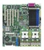
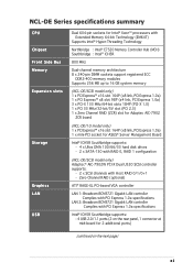
...rear panel, 1 connector at mid-board for ASUS® Server Management Board Intel® ICH5R Southbridge supports: - 4 x Ultra DMA 100/66/33 hard disk drives - 2 x SATA-150 with RAID 0, RAID 1 configuration (NCL-DE/SCSI model only) Adaptec® AIC-7902W PCI-X Dual U320 SCSI controller supports: - 2 x SCSI channels with Extended...-channel memory architecture 8 x 240-pin DIMM sockets support registered ECC DDR2-400 memory modules Supports 256 MB up to 16 GB system memory (NCL-DE/SCSI model only) 1 x PCI Express™ x16 slot 164P (x8 link, PCI Express 1.0a) 1 x PCI Express™ x8 slot ...
...rear panel, 1 connector at mid-board for ASUS® Server Management Board Intel® ICH5R Southbridge supports: - 4 x Ultra DMA 100/66/33 hard disk drives - 2 x SATA-150 with RAID 0, RAID 1 configuration (NCL-DE/SCSI model only) Adaptec® AIC-7902W PCI-X Dual U320 SCSI controller supports: - 2 x SCSI channels with Extended...-channel memory architecture 8 x 240-pin DIMM sockets support registered ECC DDR2-400 memory modules Supports 256 MB up to 16 GB system memory (NCL-DE/SCSI model only) 1 x PCI Express™ x16 slot 164P (x8 link, PCI Express 1.0a) 1 x PCI Express™ x8 slot ...
User Manual
Page 12
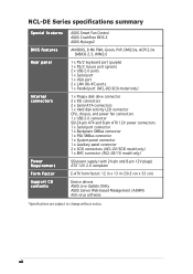
... ATX 12V power connectors 1 x Serial port connector 1 x Backplane SMBus connector 1 x PSU SMBus connector 1 x System panel connector 1 x Auxiliary panel connector 2 x SCSI connectors (NCL-DE/SCSI model only) 1 x BMC connector (NCL-DE/1U model only) SSI power supply (with 24-pin and 8-pin 12V plugs) ATX 12V 2.0 compliant E-ATX form factor: 12 in x 13 in (30.5 cm x 33 cm) Device drivers ASUS Live Update Utility ASUS Server Web...
... ATX 12V power connectors 1 x Serial port connector 1 x Backplane SMBus connector 1 x PSU SMBus connector 1 x System panel connector 1 x Auxiliary panel connector 2 x SCSI connectors (NCL-DE/SCSI model only) 1 x BMC connector (NCL-DE/1U model only) SSI power supply (with 24-pin and 8-pin 12V plugs) ATX 12V 2.0 compliant E-ATX form factor: 12 in x 13 in (30.5 cm x 33 cm) Device drivers ASUS Live Update Utility ASUS Server Web...
User Manual
Page 16
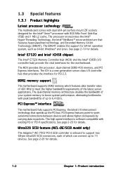
...; Xeon™ processor with existing PCI or PCI-X specifications. See page 2-20 for the motherboard. Ultra320 SCSI feature (NCL-DE/SCSI model only) The Adaptec® AIC-7902 PCI-X SCSI controller is onboard to support two 68-pin Ultra320 SCSI connectors, each of up to 15 devices. The processor incorporates the Intel® Hyper-Threading Technology, the...
...; Xeon™ processor with existing PCI or PCI-X specifications. See page 2-20 for the motherboard. Ultra320 SCSI feature (NCL-DE/SCSI model only) The Adaptec® AIC-7902 PCI-X SCSI controller is onboard to support two 68-pin Ultra320 SCSI connectors, each of up to 15 devices. The processor incorporates the Intel® Hyper-Threading Technology, the...
User Manual
Page 19
It includes description of the jumpers and connectors on the motherboard. 2 Hardware information This chapter lists the hardware setup procedures that you have to perform when installing system components.
It includes description of the jumpers and connectors on the motherboard. 2 Hardware information This chapter lists the hardware setup procedures that you have to perform when installing system components.
User Manual
Page 20
Chapter summary 2 2.1 Before you proceed 2-1 2.2 Motherboard overview 2-2 2.3 Central Processing Unit (CPU 2-10 2.4 System memory 2-14 2.5 Expansion slots 2-17 2.6 Jumpers 2-21 2.7 Connectors 2-26 ASUS NCL-DE Series
Chapter summary 2 2.1 Before you proceed 2-1 2.2 Motherboard overview 2-2 2.3 Central Processing Unit (CPU 2-10 2.4 System memory 2-14 2.5 Expansion slots 2-17 2.6 Jumpers 2-21 2.7 Connectors 2-26 ASUS NCL-DE Series
User Manual
Page 22
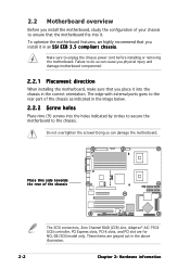
...Screw holes Place nine (9) screws into it in the above illustration. 2-2 Chapter 2: Hardware information These items are for NCL-DE/SCSI model only. The edge with external ports goes to do so can damage the motherboard. Doing so can cause you ... it . To optimize the motherboard features, we highly recommend that you install the motherboard, study the configuration of the chassis The SCSI connectors, Zero Channel RAID (ZCR) slot, Adaptec® AIC-7902 SCSI controller, PCI Express slots, PCI-X slots, and PCI slot are grayed out in an S S I E E B 3 . 5 c o m p l i a n t...
...Screw holes Place nine (9) screws into it in the above illustration. 2-2 Chapter 2: Hardware information These items are for NCL-DE/SCSI model only. The edge with external ports goes to do so can damage the motherboard. Doing so can cause you ... it . To optimize the motherboard features, we highly recommend that you install the motherboard, study the configuration of the chassis The SCSI connectors, Zero Channel RAID (ZCR) slot, Adaptec® AIC-7902 SCSI controller, PCI Express slots, PCI-X slots, and PCI slot are grayed out in an S S I E E B 3 . 5 c o m p l i a n t...
User Manual
Page 28
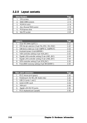
Clear RTC RAM (CLRTC1) 2. VGA controller setting (3-pin VGA_EN1) 6. Gigabit LAN controller setting (3-pin LAN1_EN1) 7. SCSI controller setting (3-pin SCSI_EN1) 9. 2.2.5 Layout contents Slots/Sockets 1. PCI/PCI-X slots 4. PCI Express slots 6. USB device wake-up...(3-pin RECOVERY1) Rear panel connectors 1. Gigabit LAN (RJ-45) ports 7. DDR2 DIMM sockets 3. Mini-PCI socket Jumpers 1. USB 2.0 ports 1 and 2 4. CPU sockets 2. Zero-Channel RAID socket 5. CPU fan pin selection (3-pin FM_CPU1, FM_CPU2) 3. PS/2 mouse port (green) 2. Parallel port (for NCL-DE model only) 3.
Clear RTC RAM (CLRTC1) 2. VGA controller setting (3-pin VGA_EN1) 6. Gigabit LAN controller setting (3-pin LAN1_EN1) 7. SCSI controller setting (3-pin SCSI_EN1) 9. 2.2.5 Layout contents Slots/Sockets 1. PCI/PCI-X slots 4. PCI Express slots 6. USB device wake-up...(3-pin RECOVERY1) Rear panel connectors 1. Gigabit LAN (RJ-45) ports 7. DDR2 DIMM sockets 3. Mini-PCI socket Jumpers 1. USB 2.0 ports 1 and 2 4. CPU sockets 2. Zero-Channel RAID socket 5. CPU fan pin selection (3-pin FM_CPU1, FM_CPU2) 3. PS/2 mouse port (green) 2. Parallel port (for NCL-DE model only) 3.
User Manual
Page 33
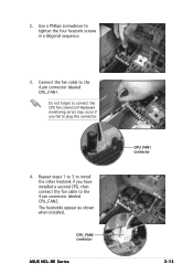
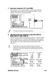
Hardware monitoring errors may occur if you have installed a second CPU, then connect the fan cable to plug this connector. 4. CPU_FAN2 connector ASUS NCL-DE Series CPU_FAN1 connector 2-13 Repeat steps 1 to 3 to install the other heatsink if you fail to the 4-pin connector labeled CPU_FAN2. 2. The heatsinks appear as shown when installed. Connect the fan cable to connect the CPU fan connector! Do not forget to the 4-pin connector labeled CPU_FAN1. Use a Phillips screwdriver to tighten the four heatsink screws in a diagonal sequence. 3.
Hardware monitoring errors may occur if you have installed a second CPU, then connect the fan cable to plug this connector. 4. CPU_FAN2 connector ASUS NCL-DE Series CPU_FAN1 connector 2-13 Repeat steps 1 to 3 to install the other heatsink if you fail to the 4-pin connector labeled CPU_FAN2. 2. The heatsinks appear as shown when installed. Connect the fan cable to connect the CPU fan connector! Do not forget to the 4-pin connector labeled CPU_FAN1. Use a Phillips screwdriver to tighten the four heatsink screws in a diagonal sequence. 3.
User Manual
Page 37
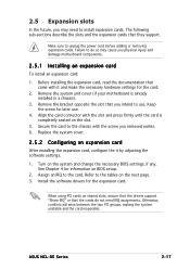
...firmly until the card is already installed in a chassis). 3. Keep the screw for the expansion card. See Chapter 4 for the card. 2. ASUS NCL-DE Series 2-17 Replace the system cover. 2.5.2 Configuring an expansion card After installing the expansion card, configure the it and make the necessary hardware settings...an expansion card: 1. Secure the card to install expansion cards. Assign an IRQ to the tables on BIOS setup. 2. Align the card connector with the screw you removed earlier. 6. When using PCI cards on the system and change the necessary BIOS settings, if any. The ...
...firmly until the card is already installed in a chassis). 3. Keep the screw for the expansion card. See Chapter 4 for the card. 2. ASUS NCL-DE Series 2-17 Replace the system cover. 2.5.2 Configuring an expansion card After installing the expansion card, configure the it and make the necessary hardware settings...an expansion card: 1. Secure the card to install expansion cards. Assign an IRQ to the tables on BIOS setup. 2. Align the card connector with the screw you removed earlier. 6. When using PCI cards on the system and change the necessary BIOS settings, if any. The ...
User Manual
Page 42
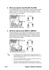
... plug. Set to +5VSB to wake up the system from S4 sleep mode (no power to the CPU fan connectors (CPU_FAN1, CPU_FAN2). USBPW12 2 1 +5V (Default) 3 2 +5VSB NCL-DE Series ® NCL-DE Series USB device wake up USBPW34 1 2 +5VSB 2 3 +5V (Default) • The USB device wake.... 2-22 Chapter 2: Hardware information 2 . CPU fan pin selection (3-pin FM_CPU1, FM_CPU2) These jumpers allow you are using the connected USB devices. NCL-DE Series ® NCL-DE Series FM_CPU setting FM_CPU1 2 1 DC mode (Default) 3 2 PWM FM_CPU2 2 1 DC mode (Default) 3 2 PWM 3 . otherwise, the...
... plug. Set to +5VSB to wake up the system from S4 sleep mode (no power to the CPU fan connectors (CPU_FAN1, CPU_FAN2). USBPW12 2 1 +5V (Default) 3 2 +5VSB NCL-DE Series ® NCL-DE Series USB device wake up USBPW34 1 2 +5VSB 2 3 +5V (Default) • The USB device wake.... 2-22 Chapter 2: Hardware information 2 . CPU fan pin selection (3-pin FM_CPU1, FM_CPU2) These jumpers allow you are using the connected USB devices. NCL-DE Series ® NCL-DE Series FM_CPU setting FM_CPU1 2 1 DC mode (Default) 3 2 PWM FM_CPU2 2 1 DC mode (Default) 3 2 PWM 3 . otherwise, the...
User Manual
Page 46
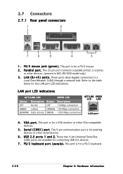
... indications. 2.7 Connectors 2.7.1 Rear panel connectors 1 2 7 6 5 4 3 1 . V G A p o r t . This 25-pin port connects a parallel printer, a scanner, or other serial devices. 6 . P S / 2 k e y b o a r d p o r t ( p u r p l e ) . Refer to a Local Area Network (LAN) through a network hub. These two 4-pin Universal Serial Bus (USB) ports are available for a PS/2 mouse. 2 . This port is for pointing devices or other devices. (present in NCL-DE/SCSI model only...
... indications. 2.7 Connectors 2.7.1 Rear panel connectors 1 2 7 6 5 4 3 1 . V G A p o r t . This 25-pin port connects a parallel printer, a scanner, or other serial devices. 6 . P S / 2 k e y b o a r d p o r t ( p u r p l e ) . Refer to a Local Area Network (LAN) through a network hub. These two 4-pin Universal Serial Bus (USB) ports are available for a PS/2 mouse. 2 . This port is for pointing devices or other devices. (present in NCL-DE/SCSI model only...
User Manual
Page 47
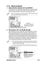
...to match the covered hole on the Ultra DMA cable connector. This prevents incorrect insertion when you must configure the second drive as a slave device by setting its jumper accordingly. NCL-DE Series ® NCL-DE Series IDE connectors ASUS NCL-DE Series SEC_IDE PIN 1 PRI_IDE PIN 1 NOTE: Orient ...the red markings (usually zigzag) on the floppy ribbon cable to PIN 1. NCL-DE Series ® FLOPPY1 PIN 1 NOTE: Orient the ...
...to match the covered hole on the Ultra DMA cable connector. This prevents incorrect insertion when you must configure the second drive as a slave device by setting its jumper accordingly. NCL-DE Series ® NCL-DE Series IDE connectors ASUS NCL-DE Series SEC_IDE PIN 1 PRI_IDE PIN 1 NOTE: Orient ...the red markings (usually zigzag) on the floppy ribbon cable to PIN 1. NCL-DE Series ® FLOPPY1 PIN 1 NOTE: Orient the ...
User Manual
Page 48
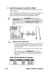
... Serial ATA hard disk drives. These connectors are for the Serial ATA signal cables for details. If you can connect Serial ATA boot/data hard disk drives to these connectors, set to the SATA1 or SATA2 connector. NCL-DE Series ® GND RSATA_RXP2 RSATA_RXN2 GND... RSATA_TXN2 RSATA_TXP2 GND GND RSATA_RXP1 RSATA_RXN1 GND RSATA_TXN1 RSATA_TXP1 GND SATA2 SATA1 NCL-DE Series SATA connectors Important notes on page 4-16 for Serial ATA...
... Serial ATA hard disk drives. These connectors are for the Serial ATA signal cables for details. If you can connect Serial ATA boot/data hard disk drives to these connectors, set to the SATA1 or SATA2 connector. NCL-DE Series ® GND RSATA_RXP2 RSATA_RXN2 GND... RSATA_TXN2 RSATA_TXP2 GND GND RSATA_RXP1 RSATA_RXN1 GND RSATA_TXN1 RSATA_TXP1 GND SATA2 SATA1 NCL-DE Series SATA connectors Important notes on page 4-16 for Serial ATA...
User Manual
Page 49
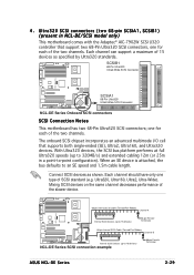
... a point-to 15 devices) NCL-DE Series SCSI connection example 68-pin Female Terminator ASUS NCL-DE Series 2-29 SCSIB1 68-Pin Ultra320/ 1 35 Ultra2-Wide SCSI Connector NCL-DE Series ® SCSIA1 68-Pin Ultra320/ Ultra2-Wide SCSI Connector 34 1 34 68 68 35 NCL-DE Series Onboard SCSI connectors SCSI Connection Notes This motherboard has two 68-Pin Ultra320 SCSI connectors; Connect SCSI devices as specified by Ultra320...
... a point-to 15 devices) NCL-DE Series SCSI connection example 68-pin Female Terminator ASUS NCL-DE Series 2-29 SCSIB1 68-Pin Ultra320/ 1 35 Ultra2-Wide SCSI Connector NCL-DE Series ® SCSIA1 68-Pin Ultra320/ Ultra2-Wide SCSI Connector 34 1 34 68 68 35 NCL-DE Series Onboard SCSI connectors SCSI Connection Notes This motherboard has two 68-Pin Ultra320 SCSI connectors; Connect SCSI devices as specified by Ultra320...
User Manual
Page 50
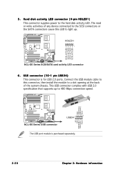
... NCL-DE Series USB connector 1 USB34 The USB port module is for USB 2.0 ports. Connect the USB module cable to this LED to a slot opening at the back of the system chassis. NCL-DE Series ® SCSI_ACTLED+ SCSI_ACTLEDSCSI_ACTLEDSCSI_ACTLED+ 5 . Hard disk activity LED connector (4-pin HDLED1) This connector supplies power to 480 Mbps connection speed. HDLED1 1 NCL-DE Series SCSI/SATA...
... NCL-DE Series USB connector 1 USB34 The USB port module is for USB 2.0 ports. Connect the USB module cable to this LED to a slot opening at the back of the system chassis. NCL-DE Series ® SCSI_ACTLED+ SCSI_ACTLEDSCSI_ACTLEDSCSI_ACTLED+ 5 . Hard disk activity LED connector (4-pin HDLED1) This connector supplies power to 480 Mbps connection speed. HDLED1 1 NCL-DE Series SCSI/SATA...
User Manual
Page 51
... Control FAN Speed FAN Power GND REAR_FAN1 CPU_FAN2 FRNT_FAN1 FRNT_FAN2 NCL-DE Series Fan connectors REAR_FAN1 GND +12V Rotation FRNT_FAN1 GND +12V Rotation REAR_FAN2 Rotation +12V GND FRNT_FAN2 GND +12V Rotation ASUS NCL-DE Series 2-31 CPU and system fan connectors (3-pin CPU_FAN1/2, REAR_FAN1/2, FRNT_FAN1/2) The fan connectors support cooling fans of 350 mA ~ 740 mA (8.88 W max...
... Control FAN Speed FAN Power GND REAR_FAN1 CPU_FAN2 FRNT_FAN1 FRNT_FAN2 NCL-DE Series Fan connectors REAR_FAN1 GND +12V Rotation FRNT_FAN1 GND +12V Rotation REAR_FAN2 Rotation +12V GND FRNT_FAN2 GND +12V Rotation ASUS NCL-DE Series 2-31 CPU and system fan connectors (3-pin CPU_FAN1/2, REAR_FAN1/2, FRNT_FAN1/2) The fan connectors support cooling fans of 350 mA ~ 740 mA (8.88 W max...

User Manual
Page 52
... Chapter 2: Hardware information Backplane SMBus connector (6-1 pin BPSMB1) This connector allows you to connect SMBus (System Management Bus) devices. BMCCONN1 NCL-DE Series BMC connector 10. Devices communicate with an SMBus host and/or other SMBus devices using the SMBus interface. BMC connector (16-pin BMCCONN1) This connector is for the ASUS server management card, if available. +5VSB...
... Chapter 2: Hardware information Backplane SMBus connector (6-1 pin BPSMB1) This connector allows you to connect SMBus (System Management Bus) devices. BMCCONN1 NCL-DE Series BMC connector 10. Devices communicate with an SMBus host and/or other SMBus devices using the SMBus interface. BMC connector (16-pin BMCCONN1) This connector is for the ASUS server management card, if available. +5VSB...
