User Guide
Page 2
... ARISING FROM ANY DEFECT OR ERROR IN THIS MANUAL OR PRODUCT. SPECIFICATIONS AND INFORMATION CONTAINED IN THIS MANUAL ARE FURNISHED FOR INFORMATIONAL USE ONLY, AND ARE SUBJECT TO CHANGE AT ANY TIME WITHOUT NOTICE, AND SHOULD NOT BE CONSTRUED AS A COMMITMENT BY ASUS. Offer to Provide Source Code of Certain Software This product contains copyrighted software that we would be...
... ARISING FROM ANY DEFECT OR ERROR IN THIS MANUAL OR PRODUCT. SPECIFICATIONS AND INFORMATION CONTAINED IN THIS MANUAL ARE FURNISHED FOR INFORMATIONAL USE ONLY, AND ARE SUBJECT TO CHANGE AT ANY TIME WITHOUT NOTICE, AND SHOULD NOT BE CONSTRUED AS A COMMITMENT BY ASUS. Offer to Provide Source Code of Certain Software This product contains copyrighted software that we would be...
User Guide
Page 6
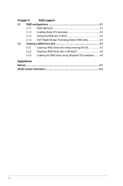
Chapter 5: RAID support 5.1 RAID configurations 5-1 5.1.1 RAID definitions 5-1 5.1.2 Installing Serial ATA hard disks 5-2 5.1.3 Setting the RAID item in BIOS 5-2 5.1.4 Intel® Rapid Storage Technology Option ROM utility 5-3 5.2 Creating a RAID driver disk 5-7 5.2.1 Creating a RAID driver disk without entering the OS 5-7 5.2.2 Creating a RAID driver disk in Windows 5-8 5.2.3 Installing the RAID driver during Windows® OS installation......... 5-8 Appendices Notices ...A-1 ASUS contact information A-4 vi
Chapter 5: RAID support 5.1 RAID configurations 5-1 5.1.1 RAID definitions 5-1 5.1.2 Installing Serial ATA hard disks 5-2 5.1.3 Setting the RAID item in BIOS 5-2 5.1.4 Intel® Rapid Storage Technology Option ROM utility 5-3 5.2 Creating a RAID driver disk 5-7 5.2.1 Creating a RAID driver disk without entering the OS 5-7 5.2.2 Creating a RAID driver disk in Windows 5-8 5.2.3 Installing the RAID driver during Windows® OS installation......... 5-8 Appendices Notices ...A-1 ASUS contact information A-4 vi
User Guide
Page 11
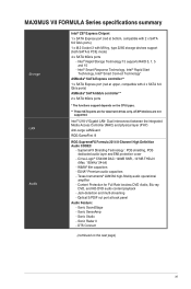
... Connect (continued on the CPU types. ** These SATA ports are not supported. Dual interconnect between the integrated Media Access Controller (MAC) and physical layer (PHY) Anti-surge LANGuard ROG GameFirst III ROG SupremeFX Formula 2014 8-Channel High Definition Audio CODEC - Sonic Studio - WIMA® film capacitors - Intel® Rapid Storage Technology 13 supports RAID 0, 1, 5 and 10 - ELNA® Premium audio capacitors - Sonic Radar II - MAXIMUS VII FORMULA Series specifications summary Storage LAN Audio Intel® Z97 Express Chipset 1 x SATA Express port...
... Connect (continued on the CPU types. ** These SATA ports are not supported. Dual interconnect between the integrated Media Access Controller (MAC) and physical layer (PHY) Anti-surge LANGuard ROG GameFirst III ROG SupremeFX Formula 2014 8-Channel High Definition Audio CODEC - Sonic Studio - WIMA® film capacitors - Intel® Rapid Storage Technology 13 supports RAID 0, 1, 5 and 10 - ELNA® Premium audio capacitors - Sonic Radar II - MAXIMUS VII FORMULA Series specifications summary Storage LAN Audio Intel® Z97 Express Chipset 1 x SATA Express port...
User Guide
Page 17
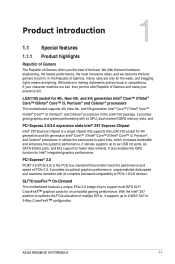
... offers you the best of multiple GPUs, it supports up to six USB 3.0 ports, six SATA 6 Gb/s ports, and M.2 support for an unrivalled gaming performance. It provides great graphics and system performance with its GPU, dual-channel DDR3 memory slots, and PCI Express 2.0/3.0 expansion slots.Intel® Z97 Express Chipset Intel® Z97 Express Chipset is the PCIe bus standard that supports the LGA1150 socket for 4th, New 4th, and 5th generation...
... offers you the best of multiple GPUs, it supports up to six USB 3.0 ports, six SATA 6 Gb/s ports, and M.2 support for an unrivalled gaming performance. It provides great graphics and system performance with its GPU, dual-channel DDR3 memory slots, and PCI Express 2.0/3.0 expansion slots.Intel® Z97 Express Chipset Intel® Z97 Express Chipset is the PCIe bus standard that supports the LGA1150 socket for 4th, New 4th, and 5th generation...
User Guide
Page 19
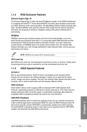
... overclock to, and the motherboard will do the rest. 1.1.4 ASUS Special Features AI Suite 3 With its user-friendly interface, ASUS AI Suite 3 consolidates all -in it the perfect motherboard for UEFI BIOS updates, and download the latest BIOS automatically. It automatically accelerates data speeds for compatible USB 3.0 peripherals without entering the existing BIOS or operating system. It also allows you get auto data backup and restore. Chapter 1 ASUS MAXIMUS VII FORMULA...
... overclock to, and the motherboard will do the rest. 1.1.4 ASUS Special Features AI Suite 3 With its user-friendly interface, ASUS AI Suite 3 consolidates all -in it the perfect motherboard for UEFI BIOS updates, and download the latest BIOS automatically. It automatically accelerates data speeds for compatible USB 3.0 peripherals without entering the existing BIOS or operating system. It also allows you get auto data backup and restore. Chapter 1 ASUS MAXIMUS VII FORMULA...
User Guide
Page 23
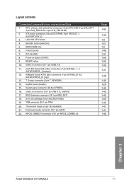
...45 1-47 1-41 1-46 Chapter 1 ASUS MAXIMUS VII FORMULA 1-7 Layout contents Connectors/Jumpers/Buttons and switches/Slots 1. USB 3.0 connector (20-1 pin USB3_12) 11. System panel connector (20-8 pin PANEL) 16. USB 2.0 connectors (10-1 pin USB1112; TPM connector (20-1 pin TPM) 20. RESET button 10. button (MemOK!) 5. Q-Code LEDs 8. CPU, chassis, and optional fan connectors (4-pin CPU_FAN; 4-pin CPU_OPT; 4-pin CHA_FAN1A-3A; 4-pin CHA_FAN1B-3B) 2. SATAEXPRESS_E1 [top]) 13. Thunderbolt header (5-pin TB_HEADER) 21. ProbeIT points 7. T_Sensor connector (2-pin T_SENSOR1) 14.
...45 1-47 1-41 1-46 Chapter 1 ASUS MAXIMUS VII FORMULA 1-7 Layout contents Connectors/Jumpers/Buttons and switches/Slots 1. USB 3.0 connector (20-1 pin USB3_12) 11. System panel connector (20-8 pin PANEL) 16. USB 2.0 connectors (10-1 pin USB1112; TPM connector (20-1 pin TPM) 20. RESET button 10. button (MemOK!) 5. Q-Code LEDs 8. CPU, chassis, and optional fan connectors (4-pin CPU_FAN; 4-pin CPU_OPT; 4-pin CHA_FAN1A-3A; 4-pin CHA_FAN1B-3B) 2. SATAEXPRESS_E1 [top]) 13. Thunderbolt header (5-pin TB_HEADER) 21. ProbeIT points 7. T_Sensor connector (2-pin T_SENSOR1) 14.

User Guide
Page 27
...socket support (Optional) 2 4 • • • • DDR3 3000 MHz capability Vendors Part No. AVEXIR A-DATA "AVD3UH31001204G4CI(XMP)" "AX3U3100W4G12DMV(XMP)" Size SS/ Chip Chip DS Brand NO. MAXIMUS VII FORMULA Motherboard Qualified Vendors Lists (QVL) DDR3 3300 MHz capability Vendors Part No. Size SS/ DS Chip Chip Brand NO. Size SS/ DS Chip Chip Brand NO. Timing Voltage... DIMM socket support (Optional) 2 4 • • • • • • • Chapter 1 ASUS MAXIMUS VII FORMULA 1-11 Size SS/ Chip Chip DS Brand NO.
...socket support (Optional) 2 4 • • • • DDR3 3000 MHz capability Vendors Part No. AVEXIR A-DATA "AVD3UH31001204G4CI(XMP)" "AX3U3100W4G12DMV(XMP)" Size SS/ Chip Chip DS Brand NO. MAXIMUS VII FORMULA Motherboard Qualified Vendors Lists (QVL) DDR3 3300 MHz capability Vendors Part No. Size SS/ DS Chip Chip Brand NO. Size SS/ DS Chip Chip Brand NO. Timing Voltage... DIMM socket support (Optional) 2 4 • • • • • • • Chapter 1 ASUS MAXIMUS VII FORMULA 1-11 Size SS/ Chip Chip DS Brand NO.
User Guide
Page 35
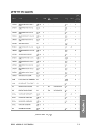
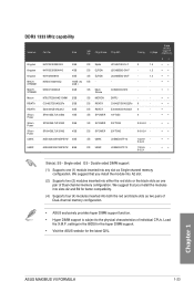
...DG - DDR3 1600 MHz capability Vendors Part No. CORSAIR CMX8GX3M2A1600C9 (Ver3.19) ...4GB ) 32GB ( 4x DS - 8GB ) 4GB ( 2x DS - 2GB ) Chip NO. - Size SS/DS Chip Brand CORSAIR CMD16GX3M2A1600C9 (Ver8.21) 16GB ( 2x DS - (XMP) 8GB ) CORSAIR...8GB ) CORSAIR CML8GX3M2A1600C9 (Ver7.12) 8GB ( 2x DS - (XMP) 4GB ) CORSAIR CMV8GX3M1A1600C11 8GB DS - Timing Voltage DIMM socket support (Optional) 2 4 9-9-9- 1.5 • 24 1600 1.5 8-8-8- 24 • • 9-9-9- 1.5 24 • •...; (continued on the next page) Chapter 1 ASUS MAXIMUS VII FORMULA 1-19
...DG - DDR3 1600 MHz capability Vendors Part No. CORSAIR CMX8GX3M2A1600C9 (Ver3.19) ...4GB ) 32GB ( 4x DS - 8GB ) 4GB ( 2x DS - 2GB ) Chip NO. - Size SS/DS Chip Brand CORSAIR CMD16GX3M2A1600C9 (Ver8.21) 16GB ( 2x DS - (XMP) 8GB ) CORSAIR...8GB ) CORSAIR CML8GX3M2A1600C9 (Ver7.12) 8GB ( 2x DS - (XMP) 4GB ) CORSAIR CMV8GX3M1A1600C11 8GB DS - Timing Voltage DIMM socket support (Optional) 2 4 9-9-9- 1.5 • 24 1600 1.5 8-8-8- 24 • • 9-9-9- 1.5 24 • •...; (continued on the next page) Chapter 1 ASUS MAXIMUS VII FORMULA 1-19
User Guide
Page 39
... red and black slots as Single-channel memory configuration. Load the X.M.P. J2108ECSE-DJ-F J2108BDBG-GN-F J4208BBBG-GN-F - Double-sided DIMM support: (1) Supports one pair of individual CPUs. Chapter 1 ASUS MAXIMUS VII FORMULA 1-23 Size KVR1333D3E9S/4G KVR1333D3N9H/4G KVR13N9S8H/4 MXD3U133316GQ MXD3V13332GS 4GB 4GB 4GB 16GB ( 4x 4GB ) 2GB MT8JTF25664AZ-1G4M1 2GB C304627CB1AG22Fe 2GB E304459CB1AG32Cf 4GB SP001GBLTU133S02 1GB SS/ DS Chip Brand Chip NO. SS...
... red and black slots as Single-channel memory configuration. Load the X.M.P. J2108ECSE-DJ-F J2108BDBG-GN-F J4208BBBG-GN-F - Double-sided DIMM support: (1) Supports one pair of individual CPUs. Chapter 1 ASUS MAXIMUS VII FORMULA 1-23 Size KVR1333D3E9S/4G KVR1333D3N9H/4G KVR13N9S8H/4 MXD3U133316GQ MXD3V13332GS 4GB 4GB 4GB 16GB ( 4x 4GB ) 2GB MT8JTF25664AZ-1G4M1 2GB C304627CB1AG22Fe 2GB E304459CB1AG32Cf 4GB SP001GBLTU133S02 1GB SS/ DS Chip Brand Chip NO. SS...
User Guide
Page 51
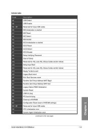
... Codes section below) Setup Input Wait Reserved for ASL (see ASL Status Codes section below) Ready To Boot event Legacy Boot event Exit Boot Services event Runtime Set Virtual Address MAP Begin Runtime Set Virtual Address MAP End Legacy Option ROM Initialization System Reset USB hot plug PCI bus hot plug Clean-up of NVRAM Configuration Reset (reset of NVRAM settings) Reserved for future AMI codes CPU initialization error System Agent initialization error (continued on the next page) Chapter 1 ASUS MAXIMUS VII FORMULA...
... Codes section below) Setup Input Wait Reserved for ASL (see ASL Status Codes section below) Ready To Boot event Legacy Boot event Exit Boot Services event Runtime Set Virtual Address MAP Begin Runtime Set Virtual Address MAP End Legacy Option ROM Initialization System Reset USB hot plug PCI bus hot plug Clean-up of NVRAM Configuration Reset (reset of NVRAM settings) Reserved for future AMI codes CPU initialization error System Agent initialization error (continued on the next page) Chapter 1 ASUS MAXIMUS VII FORMULA...

User Guide
Page 53
... These connectors connect to section SATA Configuration for details. Intel® Z97 Serial ATA 6 Gb/s connectors (7-pin SATA6G_1 - 4; If you installed Serial ATA hard disk drives, you intend to create a Serial ATA RAID set using NCQ, set the SATA Mode in the BIOS to [AHCI Mode] by default. Chapter 1 • These connectors are set the SATA Mode item in the motherboard support DVD. • When using these connectors, set to [AHCI Mode]. Refer to Serial ATA 6 Gb/s hard disk drives via Serial ATA 6 Gb/s signal cables. ASUS MAXIMUS VII FORMULA 1-37 1.2.8 Internal connectors...
... These connectors connect to section SATA Configuration for details. Intel® Z97 Serial ATA 6 Gb/s connectors (7-pin SATA6G_1 - 4; If you installed Serial ATA hard disk drives, you intend to create a Serial ATA RAID set using NCQ, set the SATA Mode in the BIOS to [AHCI Mode] by default. Chapter 1 • These connectors are set the SATA Mode item in the motherboard support DVD. • When using these connectors, set to [AHCI Mode]. Refer to Serial ATA 6 Gb/s hard disk drives via Serial ATA 6 Gb/s signal cables. ASUS MAXIMUS VII FORMULA 1-37 1.2.8 Internal connectors...
User Guide
Page 55
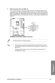
... fully use the USB 3.0 ports under Windows® 7, Windows® 8, and Windows® 8.1. • The plugged USB 3.0 device may run on xHCI or EHCI mode depending on xHCI specification. Chapter 1 ASUS MAXIMUS VII FORMULA 1-39 USB 3.0 connector (20-1 pin USB3_12) This connector allows you to install the related driver to connect a USB 3.0 module for USB-chargeable devices, optimized power efficiency, and backward compatibility with USB 2.0. The USB 3.0 module is purchased separately. • These connectors are based on the operating system's setting.
... fully use the USB 3.0 ports under Windows® 7, Windows® 8, and Windows® 8.1. • The plugged USB 3.0 device may run on xHCI or EHCI mode depending on xHCI specification. Chapter 1 ASUS MAXIMUS VII FORMULA 1-39 USB 3.0 connector (20-1 pin USB3_12) This connector allows you to install the related driver to connect a USB 3.0 module for USB-chargeable devices, optimized power efficiency, and backward compatibility with USB 2.0. The USB 3.0 module is purchased separately. • These connectors are based on the operating system's setting.

User Guide
Page 91
...the BIOS setup program can be changed. Refer to switch EZ System Tuning modes Selects the display language of the BIOS setup program Creates storage RAID and configures system overclocking Chapter 3 Displays the CPU Fan's speed. ASUS MAXIMUS VII FORMULA 3-3 Displays the CPU/motherboard temperature, CPU voltage output, CPU/chassis fan speed, and SATA information Displays the system properties of the selected mode. Click the button to manually tune the fans Enables or disables the Intel Rapid Storage Technology Loads optimized default settings Saves the changes and resets the...
...the BIOS setup program can be changed. Refer to switch EZ System Tuning modes Selects the display language of the BIOS setup program Creates storage RAID and configures system overclocking Chapter 3 Displays the CPU Fan's speed. ASUS MAXIMUS VII FORMULA 3-3 Displays the CPU/motherboard temperature, CPU voltage output, CPU/chassis fan speed, and SATA information Displays the system properties of the selected mode. Click the button to manually tune the fans Enables or disables the Intel Rapid Storage Technology Loads optimized default settings Saves the changes and resets the...
User Guide
Page 121
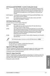
...assigned to [RAID]. When set to [Enabled], the hot plug function of commands. [RAID] Set to [RAID] when you set the SATA Mode Selection to M.2 for LPM (link power management) support with SATA Express(SATAEXPRESS_1) disabled. The connected device will then run at PCI-E mode first than SATA mode. Press to use the AHCI (Advanced Host Controller Interface). Configuration options: [On] [Off] Chapter 3 ASUS MAXIMUS VII FORMULA 3-33 Configuration options: [Disabled] [Enabled] Aggressive LPM Support [Disabled] This item is a monitoring system that SATA Express interface. The...
...assigned to [RAID]. When set to [Enabled], the hot plug function of commands. [RAID] Set to [RAID] when you set the SATA Mode Selection to M.2 for LPM (link power management) support with SATA Express(SATAEXPRESS_1) disabled. The connected device will then run at PCI-E mode first than SATA mode. Press to use the AHCI (Advanced Host Controller Interface). Configuration options: [On] [Off] Chapter 3 ASUS MAXIMUS VII FORMULA 3-33 Configuration options: [Disabled] [Enabled] Aggressive LPM Support [Disabled] This item is a monitoring system that SATA Express interface. The...
User Guide
Page 125
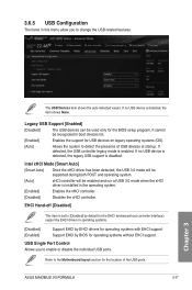
... systems with EHCI support. If no USB device is detected, the legacy USB support is installed in the operating system. [Enabled] Enables the xHCI controller. [Disabled] Disables the xHCI controller. ASUS MAXIMUS VII FORMULA 3-37 Chapter 3 If detected, the USB controller legacy mode is detected, the item shows None. Refer to [Disabled] by default for the EHCI (enhanced host controller interface) support by EHCI drivers in boot devices list. [Enabled] Enables the support for the BIOS setup program. Legacy USB Support [Enabled] [Disabled] The USB devices can be...
... systems with EHCI support. If no USB device is detected, the legacy USB support is installed in the operating system. [Enabled] Enables the xHCI controller. [Disabled] Disables the xHCI controller. ASUS MAXIMUS VII FORMULA 3-37 Chapter 3 If detected, the USB controller legacy mode is detected, the item shows None. Refer to [Disabled] by default for the EHCI (enhanced host controller interface) support by EHCI drivers in boot devices list. [Enabled] Enables the support for the BIOS setup program. Legacy USB Support [Enabled] [Disabled] The USB devices can be...
User Guide
Page 130
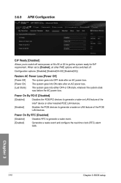
... you to switch off . When set to [Enabled], all other installed PCIE LAN devices. [Enabled] Enables the PCIE devices to generate a wake-on-LAN feature of the Intel® device or other PME options will be switched off some power at S4+S5 or S5 to get the system ready for ErP requirement. Power On By PCI-E [Disabled] [Disabled] Disables the PCIE/PCI devices to generate a wake event. [Enabled] Generates a wake event and configure the real-time clock (RTC) alarm...
... you to switch off . When set to [Enabled], all other installed PCIE LAN devices. [Enabled] Enables the PCIE devices to generate a wake-on-LAN feature of the Intel® device or other PME options will be switched off some power at S4+S5 or S5 to get the system ready for ErP requirement. Power On By PCI-E [Disabled] [Disabled] Disables the PCIE/PCI devices to generate a wake event. [Enabled] Generates a wake event and configure the real-time clock (RTC) alarm...
User Guide
Page 136
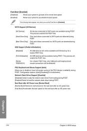
... boot after an AC power loss. SATA Support [All Devices] [All Devices] [Hard Drive Only] [Boot Drive Only] All devices connected to SATA ports are detected during POST. Only hard drives connected to SATA ports are available during POST. Only boot drives connected to [Enabled]. PS/2 Keyboard and Mouse Support [Auto] Allows you set the Fast Boot to a SATA ports are detected during POST. Chapter 3 3-48 Chapter 3: BIOS setup The following items appear only when you to load the network stack driver during POST. This process extends the POST time. USB Support...
... boot after an AC power loss. SATA Support [All Devices] [All Devices] [Hard Drive Only] [Boot Drive Only] All devices connected to SATA ports are detected during POST. Only hard drives connected to SATA ports are available during POST. Only boot drives connected to [Enabled]. PS/2 Keyboard and Mouse Support [Auto] Allows you set the Fast Boot to a SATA ports are detected during POST. Chapter 3 3-48 Chapter 3: BIOS setup The following items appear only when you to load the network stack driver during POST. This process extends the POST time. USB Support...
User Guide
Page 147
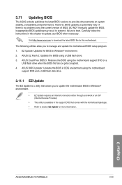
... latest BIOS file for more information. However, BIOS updating is no problem using the motherboard support DVD and a USB flash disk drive. 3.11.1 EZ Update The EZ Update is a utility that comes with the motherboard package. • Refer to manage and update the motherboard BIOS setup program. 1. ASUS CrashFree BIOS 3: Restores the BIOS using a USB flash drive. 3. Visit http://www.asus.com to update your BIOS when necessary. Chapter 3 ASUS MAXIMUS VII FORMULA 3-59 3.11 Updating BIOS The ASUS website publishes the latest BIOS versions to boot. Inappropriate BIOS updating may...
... latest BIOS file for more information. However, BIOS updating is no problem using the motherboard support DVD and a USB flash disk drive. 3.11.1 EZ Update The EZ Update is a utility that comes with the motherboard package. • Refer to manage and update the motherboard BIOS setup program. 1. ASUS CrashFree BIOS 3: Restores the BIOS using a USB flash drive. 3. Visit http://www.asus.com to update your BIOS when necessary. Chapter 3 ASUS MAXIMUS VII FORMULA 3-59 3.11 Updating BIOS The ASUS website publishes the latest BIOS versions to boot. Inappropriate BIOS updating may...
User Guide
Page 217
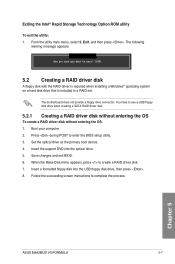
...® Rapid Storage Technology Option ROM utility To exit the utility: 1. Set the optical drive as the primary boot device. 4. The motherboard does not provide a floppy drive connector. Follow the succeeding screen instructions to exit? (Y/N): 5.2 Creating a RAID driver disk A floppy disk with the RAID driver is required when installing a Windows® operating system on a hard disk drive that is included in a RAID set. From the utility main menu, select 5. Press during POST to enter the BIOS setup utility. 3. Insert the support DVD into the USB floppy disk drive, then...
...® Rapid Storage Technology Option ROM utility To exit the utility: 1. Set the optical drive as the primary boot device. 4. The motherboard does not provide a floppy drive connector. Follow the succeeding screen instructions to exit? (Y/N): 5.2 Creating a RAID driver disk A floppy disk with the RAID driver is required when installing a Windows® operating system on a hard disk drive that is included in a RAID set. From the utility main menu, select 5. Press during POST to enter the BIOS setup utility. 3. Insert the support DVD into the USB floppy disk drive, then...
User Guide
Page 218
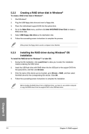
...a RAID driver disk in Windows®: 1. Place the motherboard support DVD into the optical drive, and then click Browse. 3. Select USB floppy disk drive as the destination disk. 6. Insert the USB flash drive with RAID driver into the USB port or the support DVD into the optical drive. 4. Follow the succeeding screen instructions to create a RAID driver disk. 5. Chapter 5 5-8 Chapter 5: RAID support Go to the Make Disk menu, and then click Intel AHCI/RAID Driver Disk to complete the installation. Follow the succeeding screen instructions to the USB flash drive. Plug the USB floppy...
...a RAID driver disk in Windows®: 1. Place the motherboard support DVD into the optical drive, and then click Browse. 3. Select USB floppy disk drive as the destination disk. 6. Insert the USB flash drive with RAID driver into the USB port or the support DVD into the optical drive. 4. Follow the succeeding screen instructions to create a RAID driver disk. 5. Chapter 5 5-8 Chapter 5: RAID support Go to the Make Disk menu, and then click Intel AHCI/RAID Driver Disk to complete the installation. Follow the succeeding screen instructions to the USB flash drive. Plug the USB floppy...


