
MAXIMUS V FORMULA User's Manual
Page 12
... - Fan Xpert2 - ASUS Q-Connector - ASUS CrashFree BIOS 3 - ASUS Q-LED (CPU, DRAM, VGA, Boot Device LED) - ASUS Q-DIMM (continued on the next page) xii Profile ASUS EPU Engine ASUS Wi-Fi GO! ASUS EZ Flash 2 - GPU TweakIt ROG Extreme Engine Digi+ II - 8-phase CPU power - 4-phase iGPU power - 2-phase DRAM power UEFI BIOS features - Slow Mode - MAXIMUS V FORMULA Series specifications...
... - Fan Xpert2 - ASUS Q-Connector - ASUS CrashFree BIOS 3 - ASUS Q-LED (CPU, DRAM, VGA, Boot Device LED) - ASUS Q-DIMM (continued on the next page) xii Profile ASUS EPU Engine ASUS Wi-Fi GO! ASUS EZ Flash 2 - GPU TweakIt ROG Extreme Engine Digi+ II - 8-phase CPU power - 4-phase iGPU power - 2-phase DRAM power UEFI BIOS features - Slow Mode - MAXIMUS V FORMULA Series specifications...
MAXIMUS V FORMULA User's Manual
Page 21
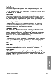
...Japan-made from a combination of 100% copper water cooling channel with adjustable CPU and memory power management frequencies. GPU.DIMM Post GPU.DIMM Post enables you to , and the motherboard will do the rest. With both water-cooling and air-cooling features, Fusion Thermo... the status of your motherboard at a hardware level. With GPU. DIMM Post, quickly and easily check your main system to a notebook through a USB cable, allowing you to achieve the best O.C. Chapter 1 ASUS MAXIMUS V FORMULA Series 1-3 USB BIOS FlashBack USB BIOS Flashback offers a hassle-free updating ...
...Japan-made from a combination of 100% copper water cooling channel with adjustable CPU and memory power management frequencies. GPU.DIMM Post GPU.DIMM Post enables you to , and the motherboard will do the rest. With both water-cooling and air-cooling features, Fusion Thermo... the status of your motherboard at a hardware level. With GPU. DIMM Post, quickly and easily check your main system to a notebook through a USB cable, allowing you to achieve the best O.C. Chapter 1 ASUS MAXIMUS V FORMULA Series 1-3 USB BIOS FlashBack USB BIOS Flashback offers a hassle-free updating ...
MAXIMUS V FORMULA User's Manual
Page 43
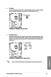
3. Slow Mode switch Slow Mode switch allows your system to provide better overclocking margins when using the Slow Mode Switch. Ensure to set the LN2 Mode jumper to [Enable] before POST to quickly load the preset profile (GO_Button file) for temporary overclocking when in OS. 4. When enabled, the Slow Mode switch prevents the system from crashing, slows down the CPU, and the system's tuner will make the adjustments. GO button Press the GO button before using the -10oC cooling system. or press it to enable MemOK! ASUS MAXIMUS V FORMULA Series 1-25 Chapter 1
3. Slow Mode switch Slow Mode switch allows your system to provide better overclocking margins when using the Slow Mode Switch. Ensure to set the LN2 Mode jumper to [Enable] before POST to quickly load the preset profile (GO_Button file) for temporary overclocking when in OS. 4. When enabled, the Slow Mode switch prevents the system from crashing, slows down the CPU, and the system's tuner will make the adjustments. GO button Press the GO button before using the -10oC cooling system. or press it to enable MemOK! ASUS MAXIMUS V FORMULA Series 1-25 Chapter 1

MAXIMUS V FORMULA User's Manual
Page 44
It allows the processor to eliminate the cold bugs in the processor during POST. 1.2.7 Jumpers 1. Chapter 1 1-26 Chapter 1: Product introduction LN2 Mode Jumper (3-pin LN2) When enabled, the LN2 Mode jumper allows your system to run at an extremely low temperature and helps the system boot fast.
It allows the processor to eliminate the cold bugs in the processor during POST. 1.2.7 Jumpers 1. Chapter 1 1-26 Chapter 1: Product introduction LN2 Mode Jumper (3-pin LN2) When enabled, the LN2 Mode jumper allows your system to run at an extremely low temperature and helps the system boot fast.
MAXIMUS V FORMULA User's Manual
Page 45
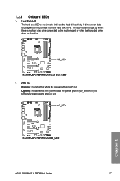
GO LED Blinking: Indicates that the system loads the preset profile (GO_Button file) for temporary overclocking when in OS. Lighting: Indicates that MemOK! 1.2.8 Onboard LEDs 1. Hard Disk LED The hard disk LED is enabled before POST. is designed to the motherboard or when the hard disk drive does not function. 2. It blinks when data is no hard disk drive connected to indicate the hard disk activity. Chapter 1 ASUS MAXIMUS V FORMULA Series 1-27 The LED does not light up when there is being written into or read from the hard disk drive.
GO LED Blinking: Indicates that the system loads the preset profile (GO_Button file) for temporary overclocking when in OS. Lighting: Indicates that MemOK! 1.2.8 Onboard LEDs 1. Hard Disk LED The hard disk LED is enabled before POST. is designed to the motherboard or when the hard disk drive does not function. 2. It blinks when data is no hard disk drive connected to indicate the hard disk activity. Chapter 1 ASUS MAXIMUS V FORMULA Series 1-27 The LED does not light up when there is being written into or read from the hard disk drive.
MAXIMUS V FORMULA User's Manual
Page 48
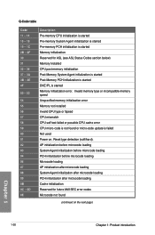
... microcode loading PCH initialization after microcode loading Cache initialization Reserved for ASL (see ASL Status Codes section below) Memory Installed CPU post-memory initialization Post-Memory System Agent initialization is started Post-Memory PCH initialization is started DXE IPL is not found (continued on . Invalid memory type or incompatible memory speed Unspecified memory...
... microcode loading PCH initialization after microcode loading Cache initialization Reserved for ASL (see ASL Status Codes section below) Memory Installed CPU post-memory initialization Post-Memory System Agent initialization is started Post-Memory PCH initialization is started DXE IPL is not found (continued on . Invalid memory type or incompatible memory speed Unspecified memory...
MAXIMUS V FORMULA User's Manual
Page 49
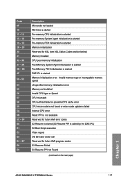
... Reserved for future AMI progress codes S3 Resume Failed S3 Resume PPI not Found (continued on the next page) Chapter 1 ASUS MAXIMUS V FORMULA Series 1-31 Invalid memory type or incompatible memory speed Unspecified memory initialization error Memory not installed Invalid CPU type or Speed CPU... repost OS S3 wake vector call Reserved for ASL (see ASL Status Codes section below) Memory Installed CPU post-memory initialization Post-Memory System Agent initialization is started Post-Memory PCH initialization is started DXE IPL is started Memory initialization error. Code 0F 10 11 - 14 15...
... Reserved for future AMI progress codes S3 Resume Failed S3 Resume PPI not Found (continued on the next page) Chapter 1 ASUS MAXIMUS V FORMULA Series 1-31 Invalid memory type or incompatible memory speed Unspecified memory initialization error Memory not installed Invalid CPU type or Speed CPU... repost OS S3 wake vector call Reserved for ASL (see ASL Status Codes section below) Memory Installed CPU post-memory initialization Post-Memory System Agent initialization is started Post-Memory PCH initialization is started DXE IPL is started Memory initialization error. Code 0F 10 11 - 14 15...
MAXIMUS V FORMULA User's Manual
Page 91
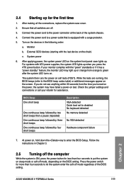
... detected Quick boot set to the BIOS beep codes table) or additional messages appear on self tests (POST). Connect the power cord to enter the BIOS Setup. If your retailer for the first time 1. Chapter 2 ASUS MAXIMUS V FORMULA Series 2-25 System power 6. After making all switches are running, the BIOS beeps (refer to disabled...
... detected Quick boot set to the BIOS beep codes table) or additional messages appear on self tests (POST). Connect the power cord to enter the BIOS Setup. If your retailer for the first time 1. Chapter 2 ASUS MAXIMUS V FORMULA Series 2-25 System power 6. After making all switches are running, the BIOS beeps (refer to disabled...
MAXIMUS V FORMULA User's Manual
Page 94
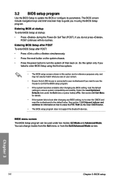
... • The BIOS setup program does not support the bluetooth devices. Entering BIOS Setup after POST To enter BIOS Setup after changing any BIOS setting, try to clear the CMOS and reset ...the motherboard to your motherboard if you do not press , POST continues with its parameters. Select the Load Optimized Defaults item under two modes: EZ Mode and ... want to use the mouse to control the BIOS setup program. • If the system becomes unstable after POST: • Press ++ simultaneously. • Press the reset button on the system chassis. • Press ...
... • The BIOS setup program does not support the bluetooth devices. Entering BIOS Setup after POST To enter BIOS Setup after changing any BIOS setting, try to clear the CMOS and reset ...the motherboard to your motherboard if you do not press , POST continues with its parameters. Select the Load Optimized Defaults item under two modes: EZ Mode and ... want to use the mouse to control the BIOS setup program. • If the system becomes unstable after POST: • Press ++ simultaneously. • Press the reset button on the system chassis. • Press ...

MAXIMUS V FORMULA User's Manual
Page 104
... ratio's long duration power. Long Duration Maintained [Auto] Allows you to maintain the turbo ratio's long duration power. Chapter 3 3-12 Chapter 3: BIOS setup GPU.DIMM Post The sub-items in this function. [Enabled] The operating system dynamically adjusts the processor voltage and core frequency which may result in a specific condition. The...
... ratio's long duration power. Long Duration Maintained [Auto] Allows you to maintain the turbo ratio's long duration power. Chapter 3 3-12 Chapter 3: BIOS setup GPU.DIMM Post The sub-items in this function. [Enabled] The operating system dynamically adjusts the processor voltage and core frequency which may result in a specific condition. The...
MAXIMUS V FORMULA User's Manual
Page 119
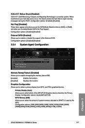
...64M] [96M] [128M] [160M] [192M] [224M] [256M] [288M][320M] [352M] [384M] [416M] [448M] [480M] [512M] [1024M] ASUS MAXIMUS V FORMULA Series 3-27 Chapter 3 Configuration options: [Enabled] [Disabled] Hot Plug [Disabled] These items appear only when you set the SATA Mode Selection item to [AHCI] or...options: [Disabled] [Enabled] 3.5.4 System Agent Configuration Memory Remap Feature [Enabled] Allows you to report warning messages during the POST. Graphics Configuration Allows you to select a primary display from iGPU, and PCIe graphical devices. Primary Display [Auto] Allows you ...
...64M] [96M] [128M] [160M] [192M] [224M] [256M] [288M][320M] [352M] [384M] [416M] [448M] [480M] [512M] [1024M] ASUS MAXIMUS V FORMULA Series 3-27 Chapter 3 Configuration options: [Enabled] [Disabled] Hot Plug [Disabled] These items appear only when you set the SATA Mode Selection item to [AHCI] or...options: [Disabled] [Enabled] 3.5.4 System Agent Configuration Memory Remap Feature [Enabled] Allows you to report warning messages during the POST. Graphics Configuration Allows you to select a primary display from iGPU, and PCIe graphical devices. Primary Display [Auto] Allows you ...

MAXIMUS V FORMULA User's Manual
Page 129
Full Screen Logo [Enabled] [Enabled] Enables the full screen logo display feature. [Disabled] Disables the full screen logo display feature. ASUS MAXIMUS V FORMULA Series 3-37 Chapter 3 3.7 Boot menu The Boot menu items allow you to [Off]. Scroll down to display the other BIOS items. Bootup ...power-on state of the NumLock to change the system boot options. The values range from 1 to [Disabled]. Post Report [5 sec] This item appears only when you to use the ASUS MyLogo 2™ feature. Set this function. [Enabled] The system waits for the key to be pressed when ...
Full Screen Logo [Enabled] [Enabled] Enables the full screen logo display feature. [Disabled] Disables the full screen logo display feature. ASUS MAXIMUS V FORMULA Series 3-37 Chapter 3 3.7 Boot menu The Boot menu items allow you to [Off]. Scroll down to display the other BIOS items. Bootup ...power-on state of the NumLock to change the system boot options. The values range from 1 to [Disabled]. Post Report [5 sec] This item appears only when you to use the ASUS MyLogo 2™ feature. Set this function. [Enabled] The system waits for the key to be pressed when ...

MAXIMUS V FORMULA User's Manual
Page 130
... items displays the available devices. Click an item to do any of the following: • Press when ASUS Logo appears. • Press after POST. • To select the boot device during system startup, press when ASUS Logo appears. UEFI/Legacy Boot [Enable both UEFI and Legacy] [Enable both UEFI and Legacy]Enables both...
... items displays the available devices. Click an item to do any of the following: • Press when ASUS Logo appears. • Press after POST. • To select the boot device during system startup, press when ASUS Logo appears. UEFI/Legacy Boot [Enable both UEFI and Legacy] [Enable both UEFI and Legacy]Enables both...
MAXIMUS V FORMULA User's Manual
Page 166
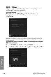
... BIOS file field, click Browse to the motherboard 1. Launching MyLogo2 To launch MyLogo2, click Update > MyLogo on the screen during the Power On Self Tests (POST).
... BIOS file field, click Browse to the motherboard 1. Launching MyLogo2 To launch MyLogo2, click Update > MyLogo on the screen during the Power On Self Tests (POST).

MAXIMUS V FORMULA User's Manual
Page 171
Click Function to operate your local system status. RC Poster RC Poster shows the status of the local system during the POST. RC Remote RC Remote allows you to monitor and record your local system through the ROG Connect cable. RC Diagram RC Diagram allows you to display more options. 2. You can switch the display mode between String and Code. Chapter 4 ASUS MAXIMUS V FORMULA Series 4-29
Click Function to operate your local system status. RC Poster RC Poster shows the status of the local system during the POST. RC Remote RC Remote allows you to monitor and record your local system through the ROG Connect cable. RC Diagram RC Diagram allows you to display more options. 2. You can switch the display mode between String and Code. Chapter 4 ASUS MAXIMUS V FORMULA Series 4-29

MAXIMUS V FORMULA User's Manual
Page 174
... to an unstable system. A wrong configuration of your system if needed. 4. Click the dropdown lists of the DRAM timings may result to save , validate and post your configuration on the ROG website depending on the desktop. 2. Your DRAM Efficiency Score will be shown in General section. Click About tab and click...
... to an unstable system. A wrong configuration of your system if needed. 4. Click the dropdown lists of the DRAM timings may result to save , validate and post your configuration on the ROG website depending on the desktop. 2. Your DRAM Efficiency Score will be shown in General section. Click About tab and click...
MAXIMUS V FORMULA User's Manual
Page 178
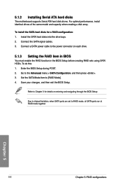
... in the BIOS Setup before creating RAID sets using SATA HDDs. Install the SATA hard disks into the drive bays. 2. Enter the BIOS Setup during POST. 2. Set the SATA Mode item to the power connector on entering and navigating through the BIOS Setup Due to chipset limitation, when SATA ports are...
... in the BIOS Setup before creating RAID sets using SATA HDDs. Install the SATA hard disks into the drive bays. 2. Enter the BIOS Setup during POST. 2. Set the SATA Mode item to the power connector on entering and navigating through the BIOS Setup Due to chipset limitation, when SATA ports are...

MAXIMUS V FORMULA User's Manual
Page 179
...at the bottom of the screen allow you to Non-RAID 6. All Rights Reserved. [ MAIN MENU ] 1. Create RAID Volume 4. Delete RAID Volume 5. Chapter 5 ASUS MAXIMUS V FORMULA Series 5-3 5.1.4 Intel® Rapid Storage Technology Option ROM utility To enter the Intel® Rapid Storage Technology Option ROM utility: 1. The utility supports maximum four... hard disk drives for reference only and may not exactly match the items on the system. 2. During POST, press + to display the utility main menu. Acceleration Options 3. Turn on your screen.
...at the bottom of the screen allow you to Non-RAID 6. All Rights Reserved. [ MAIN MENU ] 1. Create RAID Volume 4. Delete RAID Volume 5. Chapter 5 ASUS MAXIMUS V FORMULA Series 5-3 5.1.4 Intel® Rapid Storage Technology Option ROM utility To enter the Intel® Rapid Storage Technology Option ROM utility: 1. The utility supports maximum four... hard disk drives for reference only and may not exactly match the items on the system. 2. During POST, press + to display the utility main menu. Acceleration Options 3. Turn on your screen.
MAXIMUS V FORMULA User's Manual
Page 184
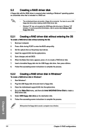
... disk with the RAID driver is required when installing a Windows® operating system on a hard disk drive that is included in Windows®: 1. Press during POST to create a RAID driver disk. 7. When the Make Disk menu appears, press to enter the BIOS setup utility. 3. Select USB floppy disk drive as the...
... disk with the RAID driver is required when installing a Windows® operating system on a hard disk drive that is included in Windows®: 1. Press during POST to create a RAID driver disk. 7. When the Make Disk menu appears, press to enter the BIOS setup utility. 3. Select USB floppy disk drive as the...


