
User Manual
Page 4
... 2-42 2.10.1 Using the OS shut down function 2-42 2.10.2 Using the dual function power switch 2-42 Chapter 3: BIOS setup 3.1 Managing and updating your BIOS 3-1 3.1.1 ASUS Update utility 3-1 3.1.2 ASUS EZ Flash 2 utility 3-4 3.1.3 ASUS CrashFree BIOS 3 utility 3-5 3.1.4 ASUS BIOS Updater 3-6 3.2 BIOS setup program 3-9 3.2.1 BIOS menu screen 3-10 3.2.2 Menu bar 3-10 3.2.3 Navigation keys 3-10 3.2.4 Menu items 3-11 3.2.5 Submenu items 3-11 3.2.6 Configuration fields...
... 2-42 2.10.1 Using the OS shut down function 2-42 2.10.2 Using the dual function power switch 2-42 Chapter 3: BIOS setup 3.1 Managing and updating your BIOS 3-1 3.1.1 ASUS Update utility 3-1 3.1.2 ASUS EZ Flash 2 utility 3-4 3.1.3 ASUS CrashFree BIOS 3 utility 3-5 3.1.4 ASUS BIOS Updater 3-6 3.2 BIOS setup program 3-9 3.2.1 BIOS menu screen 3-10 3.2.2 Menu bar 3-10 3.2.3 Navigation keys 3-10 3.2.4 Menu items 3-11 3.2.5 Submenu items 3-11 3.2.6 Configuration fields...
User Manual
Page 7
Contents 4.3.4 ASUS Fan Xpert 4-20 4.3.5 ASUS EPU-6 Engine 4-21 4.3.6 TurboV EVO 4-22 4.4 RAID configurations 4-26 4.4.1 RAID definitions 4-26 4.4.2 Installing Serial ATA hard disks 4-27 4.4.3 Setting the RAID item in BIOS 4-27 4.4.4 Intel® Matrix Storage Manager option ROM utility......... 4-27 4.5 Creating a RAID driver disk 4-31 4.5.1 Creating a RAID driver disk without entering the OS.... 4-31...
Contents 4.3.4 ASUS Fan Xpert 4-20 4.3.5 ASUS EPU-6 Engine 4-21 4.3.6 TurboV EVO 4-22 4.4 RAID configurations 4-26 4.4.1 RAID definitions 4-26 4.4.2 Installing Serial ATA hard disks 4-27 4.4.3 Setting the RAID item in BIOS 4-27 4.4.4 Intel® Matrix Storage Manager option ROM utility......... 4-27 4.5 Creating a RAID driver disk 4-31 4.5.1 Creating a RAID driver disk without entering the OS.... 4-31...

User Manual
Page 10
...: Debug code table The Appendix lists the debug code table for product and software updates. 1. ASUS websites The ASUS website provides updated information on the motherboard. • Chapter 3: BIOS setup This chapter tells how to change system settings through the BIOS Setup menus. Refer to the following parts: • Chapter 1: Product introduction This chapter describes...
...: Debug code table The Appendix lists the debug code table for product and software updates. 1. ASUS websites The ASUS website provides updated information on the motherboard. • Chapter 3: BIOS setup This chapter tells how to change system settings through the BIOS Setup menus. Refer to the following parts: • Chapter 1: Product introduction This chapter describes...
User Manual
Page 13
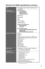
Maximus III GENE specifications summary USB ROG Exclusive Overclocking Features Other Special Features BIOS Features Manageability Back Panel I/O Ports max. 14 USB 2.0 ports (5 ports at mid-board, 9 ports at rear) ASUS Q-LED (CPU, DRAM, VGA, Boot Device LED) ASUS Q-Connector ASUS Q-Slot ASUS Q-DIMM ASUS EPU ASUS MyLogo 3 ASUS Fan Xpert ASUS EZ Flash 2 ASUS CrashFree BIOS 3 16Mb AMI BIOS, PnP, DMI2.0, WfM2.0, SM BIOS 2.4, ACPI2.0a...
Maximus III GENE specifications summary USB ROG Exclusive Overclocking Features Other Special Features BIOS Features Manageability Back Panel I/O Ports max. 14 USB 2.0 ports (5 ports at mid-board, 9 ports at rear) ASUS Q-LED (CPU, DRAM, VGA, Boot Device LED) ASUS Q-Connector ASUS Q-Slot ASUS Q-DIMM ASUS EPU ASUS MyLogo 3 ASUS Fan Xpert ASUS EZ Flash 2 ASUS CrashFree BIOS 3 16Mb AMI BIOS, PnP, DMI2.0, WfM2.0, SM BIOS 2.4, ACPI2.0a...
User Manual
Page 22
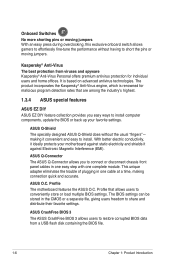
... on advanced antivirus technologies. ASUS Q-Connector The ASUS Q-Connector allows you easy ways to install computer components, update the BIOS or back up your motherboard against static electricity and shields it convenient and easy to restore corrupted BIOS data from viruses and spyware... an easy press during overclocking, this exclusive onboard switch allows gamers to effortlessly fine-tune the performance without the usual "fingers"- making connection quick and accurate. ASUS CrashFree BIOS 3 The ASUS CrashFree BIOS 3 allows users to install. It is renowned for individual ...
... on advanced antivirus technologies. ASUS Q-Connector The ASUS Q-Connector allows you easy ways to install computer components, update the BIOS or back up your motherboard against static electricity and shields it convenient and easy to restore corrupted BIOS data from viruses and spyware... an easy press during overclocking, this exclusive onboard switch allows gamers to effortlessly fine-tune the performance without the usual "fingers"- making connection quick and accurate. ASUS CrashFree BIOS 3 The ASUS CrashFree BIOS 3 allows users to install. It is renowned for individual ...
User Manual
Page 23
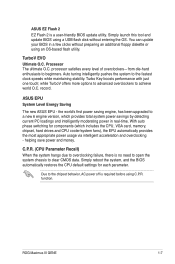
... cooler/system fans), the EPU automatically provides the most appropriate power usage via intelligent acceleration and overclocking - You can update your BIOS in real-time. With auto phase switching for each parameter. Turbo Key boosts performance with just one touch; the world's first.... Simply launch this tool and update BIOS using an OS-based flash utility. ASUS EPU System Level Energy Saving The new ASUS EPU - TurboV EVO Ultimate O.C. ROG Maximus III GENE 1-7 while TurboV offers more options to advanced overclockers to clear CMOS data. ASUS EZ Flash 2 EZ Flash 2 is...
... cooler/system fans), the EPU automatically provides the most appropriate power usage via intelligent acceleration and overclocking - You can update your BIOS in real-time. With auto phase switching for each parameter. Turbo Key boosts performance with just one touch; the world's first.... Simply launch this tool and update BIOS using an OS-based flash utility. ASUS EPU System Level Energy Saving The new ASUS EPU - TurboV EVO Ultimate O.C. ROG Maximus III GENE 1-7 while TurboV offers more options to advanced overclockers to clear CMOS data. ASUS EZ Flash 2 EZ Flash 2 is...
User Manual
Page 28
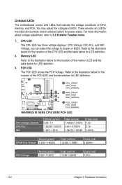
... Normal (green) 1.007-1.15275 High (yellow) 1.166-1.20575 Crazy (red) 1.219- 2-2 Chapter 2: Hardware information You may adjust the voltages in BIOS. Refer to the illustration below for the location of the CPU LED and the table below for LED definition. 2. you can select the voltage to...PCH. For more information about voltage adjustment, refer to display in BIOS. Memory LED Refer to the illustration below for the location of the PCH LED and the table below for power status. Onboard LEDs The motherboard comes with LEDs that indicate the voltage conditions of the memory ...
... Normal (green) 1.007-1.15275 High (yellow) 1.166-1.20575 Crazy (red) 1.219- 2-2 Chapter 2: Hardware information You may adjust the voltages in BIOS. Refer to the illustration below for the location of the CPU LED and the table below for LED definition. 2. you can select the voltage to...PCH. For more information about voltage adjustment, refer to display in BIOS. Memory LED Refer to the illustration below for the location of the PCH LED and the table below for power status. Onboard LEDs The motherboard comes with LEDs that indicate the voltage conditions of the memory ...

User Manual
Page 41
Size SS/ DS Chip Brand Chip NO. Timing Lable(Bios) Voltage DIMM socket support A* B* C* CORSAIR CM3X1024-1066C7 1GB DS N/A Heat-Sink Package 7 1.1 ••• Crucial CT12864BA1067.8FF 1GB SS MICRON D9KPT 7(1066-7-7-7-20) N/A •&#...; Elixir M2Y2G64CB8HA9N-BE 2GB DS N/A Heat-Sink Package (1066-7-7-7-20) N/A ••• WINTEC 3DU3191A-10 1GB DS Qimonda IDSH51-03A1F1C-10F 7 N/A •• ROG Maximus III GENE 2-15 Maximus III GENE Motherboard Qualified Vendors Lists (QVL) DDR3-1067MHz capability Vendor Part No.
Size SS/ DS Chip Brand Chip NO. Timing Lable(Bios) Voltage DIMM socket support A* B* C* CORSAIR CM3X1024-1066C7 1GB DS N/A Heat-Sink Package 7 1.1 ••• Crucial CT12864BA1067.8FF 1GB SS MICRON D9KPT 7(1066-7-7-7-20) N/A •&#...; Elixir M2Y2G64CB8HA9N-BE 2GB DS N/A Heat-Sink Package (1066-7-7-7-20) N/A ••• WINTEC 3DU3191A-10 1GB DS Qimonda IDSH51-03A1F1C-10F 7 N/A •• ROG Maximus III GENE 2-15 Maximus III GENE Motherboard Qualified Vendors Lists (QVL) DDR3-1067MHz capability Vendor Part No.

User Manual
Page 42
Maximus III GENE Motherboard Qualified Vendors Lists (QVL) DDR3-1333MHz capability Vendor Part No. A-DATA A-DATA N/A ELPIDA Apacer ELPIDA ELPIDA Apacer ELPIDA N/A N/A N/A N/A N/A MICRON MICRON MICRON MICRON MICRON MICRON NA... Package Heat-Sink Package Heat-Sink Package D9KPT MT8JF12864AY-1G4D1 D9KPT(ECC) D9KPT D9JNM D9KPT(ECC) Heat-Sink Package J1108BABG-DJ-E J1108BABG-DJ-E Timing Lable(Bios) (1333-9-9-9-24) (1333-9-9-9-24) 7-7-7-20 (1333-9-9-9-24) (1333-9-9-9-24) 9(1333-9-9-9-24) (1333-9-9-9-24) (1333-9-9-9-24) 9(1333-9-9-9-24) (1333-9-9-9-24) 9-9-9-24 (1333-9-9-9-24) (1333-9-9-9-24) ...
Maximus III GENE Motherboard Qualified Vendors Lists (QVL) DDR3-1333MHz capability Vendor Part No. A-DATA A-DATA N/A ELPIDA Apacer ELPIDA ELPIDA Apacer ELPIDA N/A N/A N/A N/A N/A MICRON MICRON MICRON MICRON MICRON MICRON NA... Package Heat-Sink Package Heat-Sink Package D9KPT MT8JF12864AY-1G4D1 D9KPT(ECC) D9KPT D9JNM D9KPT(ECC) Heat-Sink Package J1108BABG-DJ-E J1108BABG-DJ-E Timing Lable(Bios) (1333-9-9-9-24) (1333-9-9-9-24) 7-7-7-20 (1333-9-9-9-24) (1333-9-9-9-24) 9(1333-9-9-9-24) (1333-9-9-9-24) (1333-9-9-9-24) 9(1333-9-9-9-24) (1333-9-9-9-24) 9-9-9-24 (1333-9-9-9-24) (1333-9-9-9-24) ...

User Manual
Page 43
Maximus III GENE Motherboard Qualified Vendors Lists (QVL) DDR3-1333MHz... TS128MLK64V3U Transcend TS256MLK64V3U Asint SLY3128M8-EDJ Asint SLY3128M8-EDJE Asint SLZ3128M8-EDJ Asint SLZ3128M8-EDJE ASUS N/A BUFFALO FSX1333D3G-1G BUFFALO FSH1333D3G-T3G(XMP) BUFFALO Elixir Patriot FSX1333D3G-2G M2Y2G64CB8HA9N-CG... Heat-Sink Package N/A Heat-Sink Package N/A Heat-Sink Package N/A Heat-Sink Package S-POWER I0YT3E0 2GB DS S-POWER I0YT3E0 Timing Lable(Bios) 9(1066-8-8-8-20) 9(1333-9-9-9-24) (1066-6-5-5-20) 9-9-9(1066-77-7-20) 7-7-7(1066-77-7-16) 7-7-7-20(1333-99-9-24) Voltage N/A...
Maximus III GENE Motherboard Qualified Vendors Lists (QVL) DDR3-1333MHz... TS128MLK64V3U Transcend TS256MLK64V3U Asint SLY3128M8-EDJ Asint SLY3128M8-EDJE Asint SLZ3128M8-EDJ Asint SLZ3128M8-EDJE ASUS N/A BUFFALO FSX1333D3G-1G BUFFALO FSH1333D3G-T3G(XMP) BUFFALO Elixir Patriot FSX1333D3G-2G M2Y2G64CB8HA9N-CG... Heat-Sink Package N/A Heat-Sink Package N/A Heat-Sink Package N/A Heat-Sink Package S-POWER I0YT3E0 2GB DS S-POWER I0YT3E0 Timing Lable(Bios) 9(1066-8-8-8-20) 9(1333-9-9-9-24) (1066-6-5-5-20) 9-9-9(1066-77-7-20) 7-7-7(1066-77-7-16) 7-7-7-20(1333-99-9-24) Voltage N/A...

User Manual
Page 44
...Patriot PVT36G1600ELK 6GB (Kit of 3) DS Patriot PVT36G1600ELK 6GB (Kit of 3) DS PQI MFADR401PA0102(XMP) 2GB DS Chip Brand Chip NO. Timing Lable(Bios) N/A Heat-Sink Package 8-8-8-24(1333-9-9-9-24) N/A Heat-Sink Package 7-7-7-20(1333-9-9-9-24) N/A Heat-Sink Package 8-8-8-24(1601-8-8-8-24) N/A Heat-...; 1.8 •• 1.9 •• 1.65 • •• 1.65 • •• N/A • •• 2-18 Chapter 2: Hardware information Maximus III GENE Motherboard Qualified Vendors Lists (QVL) DDR3-1600MHz capability Vendor Part No.
...Patriot PVT36G1600ELK 6GB (Kit of 3) DS Patriot PVT36G1600ELK 6GB (Kit of 3) DS PQI MFADR401PA0102(XMP) 2GB DS Chip Brand Chip NO. Timing Lable(Bios) N/A Heat-Sink Package 8-8-8-24(1333-9-9-9-24) N/A Heat-Sink Package 7-7-7-20(1333-9-9-9-24) N/A Heat-Sink Package 8-8-8-24(1601-8-8-8-24) N/A Heat-...; 1.8 •• 1.9 •• 1.65 • •• 1.65 • •• N/A • •• 2-18 Chapter 2: Hardware information Maximus III GENE Motherboard Qualified Vendors Lists (QVL) DDR3-1600MHz capability Vendor Part No.

User Manual
Page 45
...-Sink Package 1800-9-9-9-27 8 8 Voltage 1.8 1.80 1.9 1.9 1.65 1.9 N/A DIMM socket support A* B* C* •• •• Maximus III GENE Motherboard Qualified Vendors Lists (QVL) DDR3-1866MHz capability Vendor CORSAIR CORSAIR KINGSTON OCZ OCZ OCZ Super Talent Patriot Patriot Part No. Timing Lable(Bios) Voltage support A* B* C* KINGSTON KHX13000D3LLK2/2GN(EPP) 2GB (Kit of 2) SS N/A Heat-Sink Package 1.9 •...
...-Sink Package 1800-9-9-9-27 8 8 Voltage 1.8 1.80 1.9 1.9 1.65 1.9 N/A DIMM socket support A* B* C* •• •• Maximus III GENE Motherboard Qualified Vendors Lists (QVL) DDR3-1866MHz capability Vendor CORSAIR CORSAIR KINGSTON OCZ OCZ OCZ Super Talent Patriot Patriot Part No. Timing Lable(Bios) Voltage support A* B* C* KINGSTON KHX13000D3LLK2/2GN(EPP) 2GB (Kit of 2) SS N/A Heat-Sink Package 1.9 •...
User Manual
Page 46
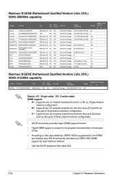
... into the blue slots (A1 and B1) as two pairs of Dual-channel memory configuration. • ASUS exclusively provides hyper DIMM support function. • Hyper DIMM support is supported for the latest QVL. 2-20...Bios) 9-9-9-27(1066-8-8-8-20) 9-9-9-28(1333-9-9-9-24) 7-8-7-20(1066-8-8-8-20) 9-9-9-24(1066-8-8-8-20) 9(1333-9-9-9-24) Voltage N/A 2 1.65 1.65 2.0 1.65 DIMM socket support A* B* C 8(1066-8-8-8-20) 1.65 ••• 9(1066-8-8-8-20) 1.65 8 1.9 9 1.9 9-8-8(1066-8-7-7-20) 1.8 7-8-7(1066-9-9-9-24) 1.65 9-9-9-24 N/A Maximus III GENE Motherboard...
... into the blue slots (A1 and B1) as two pairs of Dual-channel memory configuration. • ASUS exclusively provides hyper DIMM support function. • Hyper DIMM support is supported for the latest QVL. 2-20...Bios) 9-9-9-27(1066-8-8-8-20) 9-9-9-28(1333-9-9-9-24) 7-8-7-20(1066-8-8-8-20) 9-9-9-24(1066-8-8-8-20) 9(1333-9-9-9-24) Voltage N/A 2 1.65 1.65 2.0 1.65 DIMM socket support A* B* C 8(1066-8-8-8-20) 1.65 ••• 9(1066-8-8-8-20) 1.65 8 1.9 9 1.9 9-8-8(1066-8-7-7-20) 1.8 7-8-7(1066-9-9-9-24) 1.65 9-9-9-24 N/A Maximus III GENE Motherboard...

User Manual
Page 48
...on shared slots, ensure that the drivers support "Share IRQ" or that you physical injury and damage motherboard components. 2.5.1 Installing an expansion card To install an expansion card: 1. When using PCI cards on the...card inoperable. Failure to do not need to the tables on the system and change the necessary BIOS settings, if any. The following sub‑sections describe the slots and the expansion cards that... to the card. Remove the system unit cover (if your motherboard is completely seated on BIOS setup. 2. See Chapter 3 for information on the slot. 5.
...on shared slots, ensure that the drivers support "Share IRQ" or that you physical injury and damage motherboard components. 2.5.1 Installing an expansion card To install an expansion card: 1. When using PCI cards on the...card inoperable. Failure to do not need to the tables on the system and change the necessary BIOS settings, if any. The following sub‑sections describe the slots and the expansion cards that... to the card. Remove the system unit cover (if your motherboard is completely seated on BIOS setup. 2. See Chapter 3 for information on the slot. 5.
User Manual
Page 52
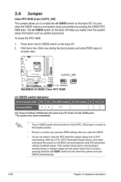
...down the clr CMOS switch will not function if the CLRTC_SW jumper is moved to the Disable position. • Ensure to re-enter your previous BIOS settings after you clear the CMOS. • You do not need to clear the RTC when the system hangs due to CPU overclocking. You ...can automatically reset CPU parameter settings to default values. With the C.P.R. (CPU Parameter Recall) feature, shut down the key during the boot process and enter BIOS setup to re-enter data. 2.6 Jumper Clear RTC RAM (3-pin CLRTC_SW) This jumper allows you to enable the clr CMOS switch on the back I/O. 2....
...down the clr CMOS switch will not function if the CLRTC_SW jumper is moved to the Disable position. • Ensure to re-enter your previous BIOS settings after you clear the CMOS. • You do not need to clear the RTC when the system hangs due to CPU overclocking. You ...can automatically reset CPU parameter settings to default values. With the C.P.R. (CPU Parameter Recall) feature, shut down the key during the boot process and enter BIOS setup to re-enter data. 2.6 Jumper Clear RTC RAM (3-pin CLRTC_SW) This jumper allows you to enable the clr CMOS switch on the back I/O. 2....
User Manual
Page 54
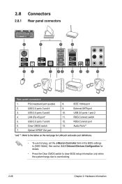
... (purple) 8. 2. See section 3.5.3 Onboard Devices Configuration for LAN port and audio port definitions. • To use hot-plug, set the J-Micron Controller item in the BIOS settings to overclocking. 2-28 Chapter 2: Hardware information Optical S/PDIF Out port IEEE 1394a port External SATA port USB 2.0 ports 1 and 2 ROG Connect switch ROG Connect... port Audio Ports** *and **: Refer to the tables on the next page for details. • Press the Clear CMOS switch to clear BIOS setup information only when the system hangs due to [AHCI Mode].
... (purple) 8. 2. See section 3.5.3 Onboard Devices Configuration for LAN port and audio port definitions. • To use hot-plug, set the J-Micron Controller item in the BIOS settings to overclocking. 2-28 Chapter 2: Hardware information Optical S/PDIF Out port IEEE 1394a port External SATA port USB 2.0 ports 1 and 2 ROG Connect switch ROG Connect... port Audio Ports** *and **: Refer to the tables on the next page for details. • Press the Clear CMOS switch to clear BIOS setup information only when the system hangs due to [AHCI Mode].

User Manual
Page 56
...through the onboard Intel® P55 chipset. • These connectors are set , refer to these connectors, set the Configure SATA as item in the BIOS to Standard IDE mode by default. In Standard IDE mode, you intend to create a Serial ATA RAID set using these connectors. See section 3.4.5 ...feature is available only if you can connect Serial ATA boot/data hard disk drives to section 4.5 RAID configurations or the manual bundled in the motherboard support DVD. • You must install Windows® XP Service Pack 2 or later versions before using hot-plug and NCQ, set the ...
...through the onboard Intel® P55 chipset. • These connectors are set , refer to these connectors, set the Configure SATA as item in the BIOS to Standard IDE mode by default. In Standard IDE mode, you intend to create a Serial ATA RAID set using these connectors. See section 3.4.5 ...feature is available only if you can connect Serial ATA boot/data hard disk drives to section 4.5 RAID configurations or the manual bundled in the motherboard support DVD. • You must install Windows® XP Service Pack 2 or later versions before using hot-plug and NCQ, set the ...
User Manual
Page 57
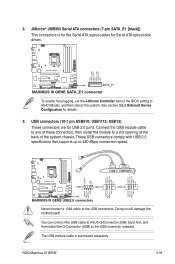
... pin USB910; Never connect a 1394 cable to the USB connector onboard. You can connect the USB cable to ASUS Q-Connector (USB, blue) first, and then install the Q-Connector (USB) to the USB connectors. USB13) ...(7-pin SATA_E1 [black]) This connectors is purchased separately. To enable hot-plugging, set the J-Micron Controller item in the BIOS setting to a slot opening at the back of these connectors, then install the module to [AHCI Mode], and then ... that supports up to 480 Mbps connection speed. Doing so will damage the motherboard! ROG Maximus III GENE 2-31 USB1112; 2.
... pin USB910; Never connect a 1394 cable to the USB connector onboard. You can connect the USB cable to ASUS Q-Connector (USB, blue) first, and then install the Q-Connector (USB) to the USB connectors. USB13) ...(7-pin SATA_E1 [black]) This connectors is purchased separately. To enable hot-plugging, set the J-Micron Controller item in the BIOS setting to a slot opening at the back of these connectors, then install the module to [AHCI Mode], and then ... that supports up to 480 Mbps connection speed. Doing so will damage the motherboard! ROG Maximus III GENE 2-31 USB1112; 2.

User Manual
Page 59
...motherboard! Connect the thermal sensor cables to monitor temperature. The thermal sensor cable is purchased separately. The optional fan1/2 can work with the temperature sensors for temperature monitoring. 6. Never connect a USB cable to a slot opening at the back of the system chassis. ROG Maximus III GENE ...2-33 Connect the IEEE 1394a module cable to this connector, then install the module to the IEEE 1394a connector. Enable OPT FAN1/2 overheat protection in BIOS if you connect thermal sensor cables to these connectors...
...motherboard! Connect the thermal sensor cables to monitor temperature. The thermal sensor cable is purchased separately. The optional fan1/2 can work with the temperature sensors for temperature monitoring. 6. Never connect a USB cable to a slot opening at the back of the system chassis. ROG Maximus III GENE ...2-33 Connect the IEEE 1394a module cable to this connector, then install the module to the IEEE 1394a connector. Enable OPT FAN1/2 overheat protection in BIOS if you connect thermal sensor cables to these connectors...

User Manual
Page 61
...the module to a slot opening at the back of the motherboard's high-definition audio capability. • If you want to connect an AC'97 front panel audio module to this connector, set the Front Panel Type item in the BIOS setup to [HD Audio]; if you connect a high-definition...module to this connector to [AC97]. By default, this connector. • We recommend that supports either HD Audio or legacy AC`97 audio standard. ROG Maximus III GENE 2-35 Front panel audio connector (10-1 pin AAFP) This connector is for a chassis-mounted front panel audio I /O module cable to [HD Audio]. ...
...the module to a slot opening at the back of the motherboard's high-definition audio capability. • If you want to connect an AC'97 front panel audio module to this connector, set the Front Panel Type item in the BIOS setup to [HD Audio]; if you connect a high-definition...module to this connector to [AC97]. By default, this connector. • We recommend that supports either HD Audio or legacy AC`97 audio standard. ROG Maximus III GENE 2-35 Front panel audio connector (10-1 pin AAFP) This connector is for a chassis-mounted front panel audio I /O module cable to [HD Audio]. ...


