
User Manual
Page 4
Profile 3-26 3.9 Exit menu 3-27 3.10 Updating BIOS 3-28 3.10.1 ASUS Update utility 3-28 3.10.2 ASUS EZ Flash 2 utility 3-31 3.10.3 ASUS BIOS Updater 3-32 Chapter 4: Software support 4.1 Installing an operating system 4-1 4.2 Support DVD information 4-1 4.2.1 Running the support DVD 4-1 4.2.2 Obtaining the software manuals 4-2 4.3 Software information 4-3 4.3.1 AI Suite II 4-3 4.3.2 ...
Profile 3-26 3.9 Exit menu 3-27 3.10 Updating BIOS 3-28 3.10.1 ASUS Update utility 3-28 3.10.2 ASUS EZ Flash 2 utility 3-31 3.10.3 ASUS BIOS Updater 3-32 Chapter 4: Software support 4.1 Installing an operating system 4-1 4.2 Support DVD information 4-1 4.2.1 Running the support DVD 4-1 4.2.2 Obtaining the software manuals 4-2 4.3 Software information 4-3 4.3.1 AI Suite II 4-3 4.3.2 ...

User Manual
Page 5
Contents 4.4 RAID configurations 4-13 4.4.1 RAID definitions 4-13 4.4.2 Installing Serial ATA hard disks 4-14 4.4.3 Setting the RAID item in BIOS 4-14 4.4.4 AMD® Option ROM Utility 4-15 4.5 Creating a RAID driver disk 4-18 4.5.1 Creating a RAID driver disk without entering the OS 4-18 4.5.2 Creating a RAID driver disk ...
Contents 4.4 RAID configurations 4-13 4.4.1 RAID definitions 4-13 4.4.2 Installing Serial ATA hard disks 4-14 4.4.3 Setting the RAID item in BIOS 4-14 4.4.4 AMD® Option ROM Utility 4-15 4.5 Creating a RAID driver disk 4-18 4.5.1 Creating a RAID driver disk without entering the OS 4-18 4.5.2 Creating a RAID driver disk ...
User Manual
Page 8
... chapter lists the hardware setup procedures that you need when installing and configuring the motherboard. ASUS websites The ASUS website provides updated information on the motherboard. • Chapter 3: BIOS setup This chapter tells how to the following parts: • Chapter 1: Product introduction This...information Refer to change system settings through the BIOS Setup menus. These documents are also provided. • Chapter 4: Software support This chapter describes the contents of the switches, jumpers, and connectors on ASUS hardware and software products. How this guide ...
... chapter lists the hardware setup procedures that you need when installing and configuring the motherboard. ASUS websites The ASUS website provides updated information on the motherboard. • Chapter 3: BIOS setup This chapter tells how to the following parts: • Chapter 1: Product introduction This...information Refer to change system settings through the BIOS Setup menus. These documents are also provided. • Chapter 4: Software support This chapter describes the contents of the switches, jumpers, and connectors on ASUS hardware and software products. How this guide ...

User Manual
Page 11
... Ai Charger+ ASUS Quiet Thermal Solution - Profile - Precision Tweaker 2 - vSB: Adjustable SB voltage at 0.00625V increment - M5A97 specifications summary ASUS unique features ASUS exclusive overclocking features Back panel I /O ports (continued on the next page) xi ASUS O.C. ASUS Q-Slot Precision Tweaker... Adjustable HT voltage at 0.00625V increment - Auto Tuning, TurboV ASUS Power Design - 4 + 2 Phase Power Design ASUS Exclusive Features - ASUS Fanless Design: Heat sink solution - Multi-language BIOS ASUS Q-Design - PCI Express frequency tuning from 100MHz up to 600MHz ...
... Ai Charger+ ASUS Quiet Thermal Solution - Profile - Precision Tweaker 2 - vSB: Adjustable SB voltage at 0.00625V increment - M5A97 specifications summary ASUS unique features ASUS exclusive overclocking features Back panel I /O ports (continued on the next page) xi ASUS O.C. ASUS Q-Slot Precision Tweaker... Adjustable HT voltage at 0.00625V increment - Auto Tuning, TurboV ASUS Power Design - 4 + 2 Phase Power Design ASUS Exclusive Features - ASUS Fanless Design: Heat sink solution - Multi-language BIOS ASUS Q-Design - PCI Express frequency tuning from 100MHz up to 600MHz ...

User Manual
Page 12
... PME, PXE Drivers ASUS utilities ASUS Update Anti-virus software (OEM version) 2 x Serial ATA 6.0 Gb/s cables 1 x I /O connectors BIOS features Manageability Support DVD contents Accessories Form factor 3 x USB 2.0/1.1 connectors support additional 6 USB ports 1 x COM connector 6 x SATA 6.0 Gb/s connectors 1 x CPU fan connector (4-pin) 2 x Chassis fan connectors (2 x 4-pin) 1 x S/PDIF Out header 1 x MemOK! xii M5A97 specifications summary Internal...
... PME, PXE Drivers ASUS utilities ASUS Update Anti-virus software (OEM version) 2 x Serial ATA 6.0 Gb/s cables 1 x I /O connectors BIOS features Manageability Support DVD contents Accessories Form factor 3 x USB 2.0/1.1 connectors support additional 6 USB ports 1 x COM connector 6 x SATA 6.0 Gb/s connectors 1 x CPU fan connector (4-pin) 2 x Chassis fan connectors (2 x 4-pin) 1 x S/PDIF Out header 1 x MemOK! xii M5A97 specifications summary Internal...

User Manual
Page 16
...0.00625V steps and DRAM voltage in the CMOS or a separate file, giving you to update the BIOS without using a bootable floppy disk or an OS-based utility. ASUS EZ DIY ASUS EZ DIY feature collection provides you to convert your favorite photo into a 256-color boot logo for...favorite settings. Users can be stored in 0.00625V steps to install computer components, update the BIOS or back up your screen. ASUS O.C. The BIOS settings can easily navigate the new UEFI BIOS with easy ways to achieve the most precise setting for experienced performance enthusiasts that allows you...
...0.00625V steps and DRAM voltage in the CMOS or a separate file, giving you to update the BIOS without using a bootable floppy disk or an OS-based utility. ASUS EZ DIY ASUS EZ DIY feature collection provides you to convert your favorite photo into a 256-color boot logo for...favorite settings. Users can be stored in 0.00625V steps to install computer components, update the BIOS or back up your screen. ASUS O.C. The BIOS settings can easily navigate the new UEFI BIOS with easy ways to achieve the most precise setting for experienced performance enthusiasts that allows you...

User Manual
Page 18
... AMD® 970 CHA_FAN1 RTL 8111E PCIEX16_1 2 EATXPWR Super I/O TPU PCIEX1_1 PCIEX1_2 ICS 9LPRS477 Lithium Cell CMOS Power M5A97 PCIEX16_2 SATA6G_6 AMD® SATA6G_5 7 SB950 ALC 887 SPDIF_OUT AAFP PCI1 8 SB_PWR 32Mb BIOS SATA6G_2 SATA6G_4 PCI2 COM1 USB1112 USB910 USB78 CLRTC SATA6G_1 SATA6G_3 PANEL 7 14 13 12 11 10 9 Refer to 2.2.8 Connectors...
... AMD® 970 CHA_FAN1 RTL 8111E PCIEX16_1 2 EATXPWR Super I/O TPU PCIEX1_1 PCIEX1_2 ICS 9LPRS477 Lithium Cell CMOS Power M5A97 PCIEX16_2 SATA6G_6 AMD® SATA6G_5 7 SB950 ALC 887 SPDIF_OUT AAFP PCI1 8 SB_PWR 32Mb BIOS SATA6G_2 SATA6G_4 PCI2 COM1 USB1112 USB910 USB78 CLRTC SATA6G_1 SATA6G_3 PANEL 7 14 13 12 11 10 9 Refer to 2.2.8 Connectors...
User Manual
Page 29
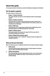
...pins 1-2. 3. For system failure due to clear the Real Time Clock (RTC) RAM in CMOS, which include system setup information such as system passwords. ASUS M5A97 2-13 Plug the power cord and turn ON the computer. 4. After clearing the CMOS, reinstall the battery. • You do not help, remove... not need to clear the RTC when the system hangs due to re-enter data. Shut down the key during the boot process and enter BIOS setup to overclocking. Chapter 2 2.2.5 Jumper Clear RTC RAM (3-pin CLRTC) This jumper allows you to overclocking, use the C.P.R. (CPU Parameter Recall) ...
...pins 1-2. 3. For system failure due to clear the Real Time Clock (RTC) RAM in CMOS, which include system setup information such as system passwords. ASUS M5A97 2-13 Plug the power cord and turn ON the computer. 4. After clearing the CMOS, reinstall the battery. • You do not help, remove... not need to clear the RTC when the system hangs due to re-enter data. Shut down the key during the boot process and enter BIOS setup to overclocking. Chapter 2 2.2.5 Jumper Clear RTC RAM (3-pin CLRTC) This jumper allows you to overclocking, use the C.P.R. (CPU Parameter Recall) ...
User Manual
Page 30
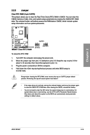
...is tested. switch Installing DIMMs that you download and update to boot and load BIOS default settings. Replace the DIMMs with the motherboard may cause system boot failure, and the DRAM_LED near the MemOK! M5A97 M5A97 MemOK! switch does not function under Windows® OS environment. • ...you turn off the system and reinstall the DIMM before using the MemOK! switch to the latest BIOS version from the ASUS website at www.asus.com. • If you that the BIOS has been restored to its default settings. • We recommend that are incompatible with ones recommended...
...is tested. switch Installing DIMMs that you download and update to boot and load BIOS default settings. Replace the DIMMs with the motherboard may cause system boot failure, and the DRAM_LED near the MemOK! M5A97 M5A97 MemOK! switch does not function under Windows® OS environment. • ...you turn off the system and reinstall the DIMM before using the MemOK! switch to the latest BIOS version from the ASUS website at www.asus.com. • If you that the BIOS has been restored to its default settings. • We recommend that are incompatible with ones recommended...

User Manual
Page 32
...Serial port connector (10-1 pin COM1) This connector is purchased separately. 2-16 Chapter 2: Hardware information Refer to [AHCI Mode]. COM1 PIN 1 M5A97 M5A97 Serial port (COM1) connector The COM module is for details. • You must install Windows® XP Service Pack 3 or later versions.... Connect the serial port module cable to this connector, then install the module to section 4.4 RAID configurations or the manual bundled in the BIOS to section 3.5.3 SATA Configuration for a serial (COM) port. AMD® SB950 Serial ATA Serial ATA 6.0 Gb/s connectors (7-pin SATA6G_1~6)...
...Serial port connector (10-1 pin COM1) This connector is purchased separately. 2-16 Chapter 2: Hardware information Refer to [AHCI Mode]. COM1 PIN 1 M5A97 M5A97 Serial port (COM1) connector The COM module is for details. • You must install Windows® XP Service Pack 3 or later versions.... Connect the serial port module cable to this connector, then install the module to section 4.4 RAID configurations or the manual bundled in the BIOS to section 3.5.3 SATA Configuration for a serial (COM) port. AMD® SB950 Serial ATA Serial ATA 6.0 Gb/s connectors (7-pin SATA6G_1~6)...

User Manual
Page 33
...USB+5V USB_P14USB_P14+ GND NC USB+5V USB_P12USB_P12+ GND NC USB+5V USB_P10USB_P10+ GND NC M5A97 PIN 1 PIN 1 PIN 1 USB+5V USB_P13USB_P13+ GND USB+5V USB_P11USB_P11+ GND USB+5V USB_P9USB_P9+ GND M5A97 USB2.0 connectors Never connect a 1394 cable to [HD Audio]; Doing so will damage the ... that you connect a high-definition front panel audio module to this connector, set the Front Panel Select item in the BIOS setup to the USB connectors. ASUS M5A97 2-17 USB1112) These connectors are for details. Front panel audio connector (10-1 pin AAFP) This connector is purchased separately...
...USB+5V USB_P14USB_P14+ GND NC USB+5V USB_P12USB_P12+ GND NC USB+5V USB_P10USB_P10+ GND NC M5A97 PIN 1 PIN 1 PIN 1 USB+5V USB_P13USB_P13+ GND USB+5V USB_P11USB_P11+ GND USB+5V USB_P9USB_P9+ GND M5A97 USB2.0 connectors Never connect a 1394 cable to [HD Audio]; Doing so will damage the ... that you connect a high-definition front panel audio module to this connector, set the Front Panel Select item in the BIOS setup to the USB connectors. ASUS M5A97 2-17 USB1112) These connectors are for details. Front panel audio connector (10-1 pin AAFP) This connector is purchased separately...

User Manual
Page 52
... detected Hardware component failure 7. Follow the instructions in the following order: a. System power 6. The system then runs the power-on the BIOS setting. Check the jumper settings and connections or call your monitor complies with ATX power supplies, the system LED lights up for assistance....power, the system power LED on test. External SCSI devices (starting with a surge protector. 5. After making all switches are running, the BIOS beeps (see anything within 30 seconds from orange to green after the system LED turns on the chain) c. If your retailer for the ...
... detected Hardware component failure 7. Follow the instructions in the following order: a. System power 6. The system then runs the power-on the BIOS setting. Check the jumper settings and connections or call your monitor complies with ATX power supplies, the system LED lights up for assistance....power, the system power LED on test. External SCSI devices (starting with a surge protector. 5. After making all switches are running, the BIOS beeps (see anything within 30 seconds from orange to green after the system LED turns on the chain) c. If your retailer for the ...

User Manual
Page 53
...• If the system fails to boot after POST, press + + , or press the reset button on to enter the Setup utility. ASUS M5A97 3-1 BIOS (Basic Input and Output System) stores system hardware settings such as storage device configuration, overclocking settings, advanced power management, and boot device configuration... the computer, the system provides you with the help of the BIOS may not exactly match what you see on how to ensure optimum performance. Chapter 3: Chapter 3 BIOS setup 3.1 Knowing BIOS The new ASUS UEFI BIOS is designed to make it as easy to use the mouse to...
...• If the system fails to boot after POST, press + + , or press the reset button on to enter the Setup utility. ASUS M5A97 3-1 BIOS (Basic Input and Output System) stores system hardware settings such as storage device configuration, overclocking settings, advanced power management, and boot device configuration... the computer, the system provides you with the help of the BIOS may not exactly match what you see on how to ensure optimum performance. Chapter 3: Chapter 3 BIOS setup 3.1 Knowing BIOS The new ASUS UEFI BIOS is designed to make it as easy to use the mouse to...
User Manual
Page 54
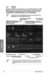
... (F8) button is available only when the boot device is installed to the system. The default screen for details. EZ Mode Tuesday [01/01/2008] M5A97 BIOS Version : 0140 CPU Type : AMD Phenom(TM) II x 4 945 Processor Total Memory : 1024 MB (DDR3 1333MHz) Exit/Advanced Mode Build Date : 05/09/...Mode, click Exit/Advanced Mode, then select Advanced Mode. Selects the display language of the selected mode on the right hand side Normal mode ASUS Optimal mode Selects the boot device priority • The boot device options vary depending on the devices you to display all fan speeds if ...
... (F8) button is available only when the boot device is installed to the system. The default screen for details. EZ Mode Tuesday [01/01/2008] M5A97 BIOS Version : 0140 CPU Type : AMD Phenom(TM) II x 4 945 Processor Total Memory : 1024 MB (DDR3 1333MHz) Exit/Advanced Mode Build Date : 05/09/...Mode, click Exit/Advanced Mode, then select Advanced Mode. Selects the display language of the selected mode on the right hand side Normal mode ASUS Optimal mode Selects the boot device priority • The boot device options vary depending on the devices you to display all fan speeds if ...
User Manual
Page 55
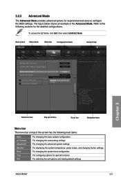
...bar Navigation keys Menu bar The menu bar on top of the Advanced Mode. Back button Menu items Menu bar Configuration fields UEFI BIOS Utility - Copyright (C) 2011 American Megatrends, Inc. 3.2.2 Advanced Mode The Advanced Mode provides advanced options for experienced end-users to the....1201. To access the EZ Mode, click Exit, then select ASUS EZ Mode. The figure below shows an example of the screen has the following sections for special functions For selecting the exit options and loading default settings Chapter 3 ASUS M5A97 3-3 Refer to configure the BIOS settings.
...bar Navigation keys Menu bar The menu bar on top of the Advanced Mode. Back button Menu items Menu bar Configuration fields UEFI BIOS Utility - Copyright (C) 2011 American Megatrends, Inc. 3.2.2 Advanced Mode The Advanced Mode provides advanced options for experienced end-users to the....1201. To access the EZ Mode, click Exit, then select ASUS EZ Mode. The figure below shows an example of the screen has the following sections for special functions For selecting the exit options and loading default settings Chapter 3 ASUS M5A97 3-3 Refer to configure the BIOS settings.
User Manual
Page 56
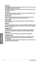
... items. The other items on the screen. Navigation keys At the bottom right corner of a menu screen when there are the navigation keys for the BIOS setup program. Configuration fields These fields show the values for the menu items. If an item is not user-configurable. Chapter 3 3-4 Chapter... 3: BIOS setup Use the navigation keys to display a pop-up window Select a menu item and press to select items in the menu and change the value ...
... items. The other items on the screen. Navigation keys At the bottom right corner of a menu screen when there are the navigation keys for the BIOS setup program. Configuration fields These fields show the values for the menu items. If an item is not user-configurable. Chapter 3 3-4 Chapter... 3: BIOS setup Use the navigation keys to display a pop-up window Select a menu item and press to select items in the menu and change the value ...

User Manual
Page 57
... CMOS Real Time Clock (RTC) RAM to change the system security settings. UEFI BIOS Utility - After you to clear the BIOS password. Advanced Mode Exit Main Ai Tweaker Advanced Monitor BIOS Information BIOS Version Build Date 0140 x64 05/09/2011 CPU Information AMD Phenom(TM) II ... Change Opt. F1: General Help Security The Security menu items allow you set , then this is a power on top of the BIOS Setup program. Chapter 3 ASUS M5A97 3-5 See section 2.2.5 Jumpers for when entering Setup If ONLY the User's password is set a password, these items show the default Not...
... CMOS Real Time Clock (RTC) RAM to change the system security settings. UEFI BIOS Utility - After you to clear the BIOS password. Advanced Mode Exit Main Ai Tweaker Advanced Monitor BIOS Information BIOS Version Build Date 0140 x64 05/09/2011 CPU Information AMD Phenom(TM) II ... Change Opt. F1: General Help Security The Security menu items allow you set , then this is a power on top of the BIOS Setup program. Chapter 3 ASUS M5A97 3-5 See section 2.2.5 Jumpers for when entering Setup If ONLY the User's password is set a password, these items show the default Not...

User Manual
Page 58
... Password item and press . 2. To clear the administrator password, follow the same steps as in the BIOS setup program. The User Password item on top of the screen shows the default Not Installed. Chapter 3 3-6 Chapter 3: BIOS setup To change a user password: 1. To set a password, this item shows Installed. Administrator Password If you...
... Password item and press . 2. To clear the administrator password, follow the same steps as in the BIOS setup program. The User Password item on top of the screen shows the default Not Installed. Chapter 3 3-6 Chapter 3: BIOS setup To change a user password: 1. To set a password, this item shows Installed. Administrator Password If you...

User Manual
Page 59
Copyright (C) 2011 American Megatrends, Inc. ASUS M5A97 3-7 Advanced Mode Exit Main Ai Tweaker Advanced Monitor Current CPU Speed : xxxxMHz Target CPU Speed : xxxxMHz Current Memory Frequency : xxxxMHz Current NB Fruquency : xxxxMHz Current ..., Inc. Scroll down to malfunction. F1: General Help F2: Previous Values F5: Optimized Defaults F10: Save ESC: Exit F12: Print Screen Version 2.00.1201. UEFI BIOS Utility - 3.4 Ai Tweaker menu The Ai Tweaker menu items allow you installed on the CPU and DIMM model you to configure overclocking-related items. Be...
Copyright (C) 2011 American Megatrends, Inc. ASUS M5A97 3-7 Advanced Mode Exit Main Ai Tweaker Advanced Monitor Current CPU Speed : xxxxMHz Target CPU Speed : xxxxMHz Current Memory Frequency : xxxxMHz Current NB Fruquency : xxxxMHz Current ..., Inc. Scroll down to malfunction. F1: General Help F2: Previous Values F5: Optimized Defaults F10: Save ESC: Exit F12: Print Screen Version 2.00.1201. UEFI BIOS Utility - 3.4 Ai Tweaker menu The Ai Tweaker menu items allow you installed on the CPU and DIMM model you to configure overclocking-related items. Be...

User Manual
Page 60
... and voltage of these preset overclocking configuration options: [Auto] Loads the optimal settings for the following sub-items vary depending on the motherboard. Chapter 3 3-8 Chapter 3: BIOS setup Ai Overclock Tuner [Auto] Allows you to adjust PCIE frequency to achieve the desired CPU internal frequency. You can also key in the desired...
... and voltage of these preset overclocking configuration options: [Auto] Loads the optimal settings for the following sub-items vary depending on the motherboard. Chapter 3 3-8 Chapter 3: BIOS setup Ai Overclock Tuner [Auto] Allows you to adjust PCIE frequency to achieve the desired CPU internal frequency. You can also key in the desired...


