User Manual
Page 3
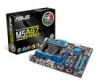
Contents Notices ...vi Safety information...vii About this guide...viii M5A97 PRO specifications summary x Chapter 1: Product introduction 1.1 Welcome!...1-1 1.2 Package contents 1-1 1.3 Special features 1-2 1.3.1 Product highlights 1-2 1.3.2 Dual Intelligent Processors 2 with DIGI+ VRM 1-2 1.3.3 ASUS Exclusive Features 1-3 1.3.4 ASUS Quiet Thermal Solution 1-4 1.3.5 ASUS EZ DIY 1-4 1.3.6 Other special features 1-5 Chapter 2: Hardware information 2.1 Before you proceed 2-1 2.2 Motherboard overview 2-2 2.2.1 Motherboard layout 2-2 2.2.2 Central Processing Unit...
Contents Notices ...vi Safety information...vii About this guide...viii M5A97 PRO specifications summary x Chapter 1: Product introduction 1.1 Welcome!...1-1 1.2 Package contents 1-1 1.3 Special features 1-2 1.3.1 Product highlights 1-2 1.3.2 Dual Intelligent Processors 2 with DIGI+ VRM 1-2 1.3.3 ASUS Exclusive Features 1-3 1.3.4 ASUS Quiet Thermal Solution 1-4 1.3.5 ASUS EZ DIY 1-4 1.3.6 Other special features 1-5 Chapter 2: Hardware information 2.1 Before you proceed 2-1 2.2 Motherboard overview 2-2 2.2.1 Motherboard layout 2-2 2.2.2 Central Processing Unit...

User Manual
Page 11
.../NB voltage at 0.00625V increment - Industry leading Digital 6+2 Phase Power Design - AI Suite II - PCI Express frequency tuning from 100MHz up to 600MHz at 1MHz increment Overclocking Protection: - ASUS Q-Connector ASUS EZ DIY: - M5A97 PRO specifications summary ASUS unique features ASUS exclusive overclocking features ASUS Dual Intelligent Processors 2 with DIGI+ VRM: ASUS DIGI+ VRM - AI Charger+ ASUS Quiet Thermal Solution...
.../NB voltage at 0.00625V increment - Industry leading Digital 6+2 Phase Power Design - AI Suite II - PCI Express frequency tuning from 100MHz up to 600MHz at 1MHz increment Overclocking Protection: - ASUS Q-Connector ASUS EZ DIY: - M5A97 PRO specifications summary ASUS unique features ASUS exclusive overclocking features ASUS Dual Intelligent Processors 2 with DIGI+ VRM: ASUS DIGI+ VRM - AI Charger+ ASUS Quiet Thermal Solution...

User Manual
Page 16
... controls of the chipset and power phase area through high efficient heat-exchange. This unique module eliminates the trouble of Q-LED, Q-Slot and Q-DIMM design speed up and simplify the DIY process! Supports Hard Drives over 2.2TB ASUS UEFI BIOS natively supports hard drives...update the BIOS without using a bootable floppy disk or an OS-based utility. 1-4 Chapter 1: Product Introduction ASUS Q-Design ASUS Q-Design enhances your PC's loading. ASUS EZ-Flash 2 ASUS EZ Flash 2 is an Unified Extensible Firmware Interface, offering a userfriendly interface that allows you to enable more...
... controls of the chipset and power phase area through high efficient heat-exchange. This unique module eliminates the trouble of Q-LED, Q-Slot and Q-DIMM design speed up and simplify the DIY process! Supports Hard Drives over 2.2TB ASUS UEFI BIOS natively supports hard drives...update the BIOS without using a bootable floppy disk or an OS-based utility. 1-4 Chapter 1: Product Introduction ASUS Q-Design ASUS Q-Design enhances your PC's loading. ASUS EZ-Flash 2 ASUS EZ Flash 2 is an Unified Extensible Firmware Interface, offering a userfriendly interface that allows you to enable more...
User Manual
Page 21
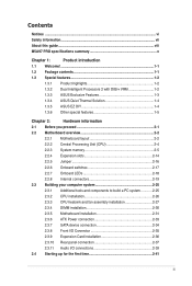
..., USB1112, USB1314) 11. Digital audio connector (4-1 pin SPDIF_OUT) Page 2-23 2-4 2-22 2-5 2-17 2-19 2-16 2-24 2-21 2-20 2-18 2-21 2-20 Chapter 2 ASUS M5A97 PRO 2-3 CPU socket AM3+ 3. MemOK! Standby power LED (SB_PWR) 12. ATX power connectors (24-pin EATXPWR, 8-pin EATX12V) 2. Front panel audio connector (10-1 pin AAFP) 13. Clear RTC RAM (CLRTC) 8. Serial port connector...
..., USB1112, USB1314) 11. Digital audio connector (4-1 pin SPDIF_OUT) Page 2-23 2-4 2-22 2-5 2-17 2-19 2-16 2-24 2-21 2-20 2-18 2-21 2-20 Chapter 2 ASUS M5A97 PRO 2-3 CPU socket AM3+ 3. MemOK! Standby power LED (SB_PWR) 12. ATX power connectors (24-pin EATXPWR, 8-pin EATX12V) 2. Front panel audio connector (10-1 pin AAFP) 13. Clear RTC RAM (CLRTC) 8. Serial port connector...
User Manual
Page 35
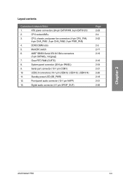
...to boot due to BIOS overclocking, press the MemOK! The blinking speed of failsafe settings. ASUS M5A97 PRO 2-17 switch until the DRAM_LED starts blinking to begin automatic memory compatibility tuning for the ... to the latest BIOS version from the ASUS website at www.asus.com. • If you turn off the computer and unplug the power cord for overclockers and gamers who continually...fine-tune performance when working on the computer. Chapter 2 • Refer to section 2.2.7 Onboard LEDs for the exact location of failsafe settings. If the test fails, the system reboots and test ...
...to boot due to BIOS overclocking, press the MemOK! The blinking speed of failsafe settings. ASUS M5A97 PRO 2-17 switch until the DRAM_LED starts blinking to begin automatic memory compatibility tuning for the ... to the latest BIOS version from the ASUS website at www.asus.com. • If you turn off the computer and unplug the power cord for overclockers and gamers who continually...fine-tune performance when working on the computer. Chapter 2 • Refer to section 2.2.7 Onboard LEDs for the exact location of failsafe settings. If the test fails, the system reboots and test ...

User Manual
Page 36
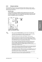
Standby Power LED The motherboard comes with a standby power LED. The illustration below shows the location of CPU, DRAM, VGA card, and HDD indicate key components status during POST (Power-on Self Test). POST State LEDs The POST State LEDs of the onboard LED. If an error is found , the LED next ... This user-friendly design provides an intuitional way to indicate that you should shut down the system and unplug the power cable before removing or plugging in soft‑off mode. 2.2.7 Onboard LEDs 1. The green LED lights up to locate the root problem within a second. 2.
Standby Power LED The motherboard comes with a standby power LED. The illustration below shows the location of CPU, DRAM, VGA card, and HDD indicate key components status during POST (Power-on Self Test). POST State LEDs The POST State LEDs of the onboard LED. If an error is found , the LED next ... This user-friendly design provides an intuitional way to indicate that you should shut down the system and unplug the power cable before removing or plugging in soft‑off mode. 2.2.7 Onboard LEDs 1. The green LED lights up to locate the root problem within a second. 2.
User Manual
Page 42
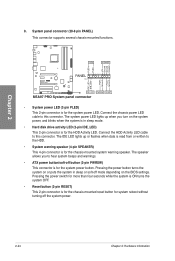
... IDE_LED) This 2-pin connector is for the system power LED. Connect the HDD Activity LED cable to hear system beeps and warnings. • ATX power button/soft-off the system power. 2-24 Chapter 2: Hardware information The IDE LED lights up when you to this connector. Connect the chassis power LED cable to the HDD. • System warning speaker...
... IDE_LED) This 2-pin connector is for the system power LED. Connect the HDD Activity LED cable to hear system beeps and warnings. • ATX power button/soft-off the system power. 2-24 Chapter 2: Hardware information The IDE LED lights up when you to this connector. Connect the chassis power LED cable to the HDD. • System warning speaker...

User Manual
Page 59
... retailer for less than four seconds lets the system enter the soft-off mode regardless of the system chassis. 4. After applying power, the system power LED on the system front panel case lights up or change from the time you turned on the devices in Chapter 3. 2.5 Turning... with a surge protector. 5. Turn on the power, the system may light up . While the tests are off mode, depending on , hold down the key to disabled No keyboard detected No memory detected No VGA detected Hardware component failure 7. ASUS M5A97 PRO 2-41 Monitor b. BIOS Beep One short beep ...
... retailer for less than four seconds lets the system enter the soft-off mode regardless of the system chassis. 4. After applying power, the system power LED on the system front panel case lights up or change from the time you turned on the devices in Chapter 3. 2.5 Turning... with a surge protector. 5. Turn on the power, the system may light up . While the tests are off mode, depending on , hold down the key to disabled No keyboard detected No memory detected No VGA detected Hardware component failure 7. ASUS M5A97 PRO 2-41 Monitor b. BIOS Beep One short beep ...
User Manual
Page 81
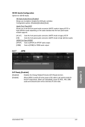
... Related Products (ErP) Ready function. [Enabled] Allows BIOS to switch off some power at S5 to get the system ready for WOL, WO_USB, audio and onboard LEDs will be switched off . Chapter 3 ASUS M5A97 PRO 3-21 Advanced Mode Exit Main Back Ai Tweaker Advanced\ APM > ErP Ready Advanced... Monitor Enabled Boot Tool Allow BIOS to switch off some power at S5 state. When set to Enabled,...
... Related Products (ErP) Ready function. [Enabled] Allows BIOS to switch off some power at S5 to get the system ready for WOL, WO_USB, audio and onboard LEDs will be switched off . Chapter 3 ASUS M5A97 PRO 3-21 Advanced Mode Exit Main Back Ai Tweaker Advanced\ APM > ErP Ready Advanced... Monitor Enabled Boot Tool Allow BIOS to switch off some power at S5 state. When set to Enabled,...


