User Manual
Page 3
...this guide...viii M5A97 PRO specifications summary x Chapter 1: Product introduction 1.1 Welcome!...1-1 1.2 Package contents 1-1 1.3 Special features 1-2 1.3.1 Product highlights 1-2 1.3.2 Dual Intelligent Processors 2 with DIGI+ VRM 1-2 1.3.3 ASUS Exclusive Features 1-3 1.3.4 ASUS Quiet Thermal Solution 1-4 1.3.5 ASUS EZ DIY 1-4...heatsink and fan assembly installation 2-27 2.3.4 DIMM installation 2-30 2.3.5 Motherboard installation 2-31 2.3.6 ATX Power connection 2-33 2.3.7 SATA device connection 2-34 2.3.8 Front I/O Connector 2-35 2.3.9 Expension Card installation...
...this guide...viii M5A97 PRO specifications summary x Chapter 1: Product introduction 1.1 Welcome!...1-1 1.2 Package contents 1-1 1.3 Special features 1-2 1.3.1 Product highlights 1-2 1.3.2 Dual Intelligent Processors 2 with DIGI+ VRM 1-2 1.3.3 ASUS Exclusive Features 1-3 1.3.4 ASUS Quiet Thermal Solution 1-4 1.3.5 ASUS EZ DIY 1-4...heatsink and fan assembly installation 2-27 2.3.4 DIMM installation 2-30 2.3.5 Motherboard installation 2-31 2.3.6 ATX Power connection 2-33 2.3.7 SATA device connection 2-34 2.3.8 Front I/O Connector 2-35 2.3.9 Expension Card installation...
User Manual
Page 7
.... • Avoid dust, humidity, and temperature extremes. Safety information Electrical safety • To prevent electrical shock hazard, disconnect the power cable from the electrical outlet before relocating the system. • When adding or removing devices to fix it by yourself. These devices... could interrupt the grounding circuit. • Ensure that all power cables from the existing system before you are unplugged. • Seek professional assistance before using , contact your dealer immediately. •...
.... • Avoid dust, humidity, and temperature extremes. Safety information Electrical safety • To prevent electrical shock hazard, disconnect the power cable from the electrical outlet before relocating the system. • When adding or removing devices to fix it by yourself. These devices... could interrupt the grounding circuit. • Ensure that all power cables from the existing system before you are unplugged. • Seek professional assistance before using , contact your dealer immediately. •...

User Manual
Page 11
... ASUS C.P.R.(CPU Parameter Recall) (continued on the next page) xi M5A97 PRO specifications summary ASUS unique features ASUS exclusive overclocking features ASUS Dual Intelligent Processors 2 with DIGI+ VRM: ASUS DIGI+ VRM - ASUS Fanless Design: Heat sink solution - EPU ASUS TPU - AI Suite II - ASUS O.C. ASUS ...00500V increment SFS (Stepless Frequency Selection): - Industry leading Digital 6+2 Phase Power Design - ASUS UEFI BIOS EZ Mode featuring friendly graphics user interface - MemOK! - ASUS Q-DIMM - ASUS Q-LED (CPU, DRAM, VGA, Boot Device LED) - vCore: Adjustable...
... ASUS C.P.R.(CPU Parameter Recall) (continued on the next page) xi M5A97 PRO specifications summary ASUS unique features ASUS exclusive overclocking features ASUS Dual Intelligent Processors 2 with DIGI+ VRM: ASUS DIGI+ VRM - ASUS Fanless Design: Heat sink solution - EPU ASUS TPU - AI Suite II - ASUS O.C. ASUS ...00500V increment SFS (Stepless Frequency Selection): - Industry leading Digital 6+2 Phase Power Design - ASUS UEFI BIOS EZ Mode featuring friendly graphics user interface - MemOK! - ASUS Q-DIMM - ASUS Q-LED (CPU, DRAM, VGA, Boot Device LED) - vCore: Adjustable...

User Manual
Page 12
M5A97 PRO specifications summary Back panel I/O ports Internal I/O connectors BIOS features Manageability Support DVD contents Form factor 1 x PS/2 keyboard/mouse combo port 1 x Optical S/PDIF Out port 1 x LAN (... panel audio connector 1 x S/PDIF Out header 1 x Clear CMOS jumper 24-pin EATX Power connector 8-pin EATX 12V Power connector System Panel (Q-Connector) 1 x MemOK! button 32 Mb Flash ROM, UEFI BIOS, PnP, DMI 2.0, WfM 2.0, SM BIOS 2.6, ACPI 2.0a, Multi-language BIOS, ASUS EZ Flash 2 WfM 2.0, DMI 2.0, WOL by PME, WOR by PME, PXE Drivers...
M5A97 PRO specifications summary Back panel I/O ports Internal I/O connectors BIOS features Manageability Support DVD contents Form factor 1 x PS/2 keyboard/mouse combo port 1 x Optical S/PDIF Out port 1 x LAN (... panel audio connector 1 x S/PDIF Out header 1 x Clear CMOS jumper 24-pin EATX Power connector 8-pin EATX 12V Power connector System Panel (Q-Connector) 1 x MemOK! button 32 Mb Flash ROM, UEFI BIOS, PnP, DMI 2.0, WfM 2.0, SM BIOS 2.6, ACPI 2.0a, Multi-language BIOS, ASUS EZ Flash 2 WfM 2.0, DMI 2.0, WOL by PME, WOR by PME, PXE Drivers...

User Manual
Page 14
.... 1.3.2 Dual Intelligent Processors 2 with rendering speed, eliminating the need to scale down screen resolution to ensure optimized performance, extreme system stability and greater power efficiency. 1-2 Chapter 1: Product Introduction Chapter 1 1.3 Special features 1.3.1 Product highlights AMD® Socket AM3+; It features dual-channel DDR3 memory support ...8482; Support ATI's CrossFireX™ boosts image quality along with DIGI+ VRM The world's first Dual Intelligent Processors from ASUS pioneered the use of the latest 3D graphics, multimedia, and Internet applications.
.... 1.3.2 Dual Intelligent Processors 2 with rendering speed, eliminating the need to scale down screen resolution to ensure optimized performance, extreme system stability and greater power efficiency. 1-2 Chapter 1: Product Introduction Chapter 1 1.3 Special features 1.3.1 Product highlights AMD® Socket AM3+; It features dual-channel DDR3 memory support ...8482; Support ATI's CrossFireX™ boosts image quality along with DIGI+ VRM The world's first Dual Intelligent Processors from ASUS pioneered the use of the latest 3D graphics, multimedia, and Internet applications.

User Manual
Page 15
...ASUS M5A97 PRO 1-3 This also reduces fan noise and extends component longevity. 1.3.3 ASUS Exclusive Features MemOK! determines failsafe settings and dramatically improves your performance with no need to enhance system stability through enabling VRM spread spectrum. This all the exclusive ASUS features into the world's first real-time PC power...to ensure optimized performance, extreme system stability, and greater power efficiency. 2X Precise Power Control ASUS DIGI+ VRM delivers twice the precision power, intelligently adjusting PWM voltage and frequency modulation to supervise ...
...ASUS M5A97 PRO 1-3 This also reduces fan noise and extends component longevity. 1.3.3 ASUS Exclusive Features MemOK! determines failsafe settings and dramatically improves your performance with no need to enhance system stability through enabling VRM spread spectrum. This all the exclusive ASUS features into the world's first real-time PC power...to ensure optimized performance, extreme system stability, and greater power efficiency. 2X Precise Power Control ASUS DIGI+ VRM delivers twice the precision power, intelligently adjusting PWM voltage and frequency modulation to supervise ...

User Manual
Page 16
... cables to achieve a quiet and cool environment. 1.3.5 ASUS EZ DIY ASUS UEFI BIOS (EZ Mode) The new ASUS UEFI BIOS is for motherboard users, but also the heatsink design lowers the temperature of the chipset and power phase area through high efficient heat-exchange. All of ...connecting the system panel cables one at a time and avoiding wrong cable connections. Chapter 1 1.3.4 ASUS Quiet Thermal Solution ASUS Fanless Design-Heat-sink solution The stylish heatsink ...
... cables to achieve a quiet and cool environment. 1.3.5 ASUS EZ DIY ASUS UEFI BIOS (EZ Mode) The new ASUS UEFI BIOS is for motherboard users, but also the heatsink design lowers the temperature of the chipset and power phase area through high efficient heat-exchange. All of ...connecting the system panel cables one at a time and avoiding wrong cable connections. Chapter 1 1.3.4 ASUS Quiet Thermal Solution ASUS Fanless Design-Heat-sink solution The stylish heatsink ...

User Manual
Page 19
...2.1 Before you proceed Take note of the following precautions before you install motherboard components or change any motherboard settings. • Unplug the power cord from the wall socket before touching any component. • Before handling components, use a grounded wrist strap or touch a safely grounded...power supply is switched off or the power cord is detached from the power supply. Failure to do so may cause severe damage to avoid touching the ICs on them due to static electricity. • Hold components by the edges to the motherboard, peripherals, or components. ASUS M5A97 PRO...
...2.1 Before you proceed Take note of the following precautions before you install motherboard components or change any motherboard settings. • Unplug the power cord from the wall socket before touching any component. • Before handling components, use a grounded wrist strap or touch a safely grounded...power supply is switched off or the power cord is detached from the power supply. Failure to do so may cause severe damage to avoid touching the ICs on them due to static electricity. • Hold components by the edges to the motherboard, peripherals, or components. ASUS M5A97 PRO...
User Manual
Page 21
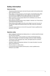
.... CPU socket AM3+ 3. Clear RTC RAM (CLRTC) 8. Digital audio connector (4-1 pin SPDIF_OUT) Page 2-23 2-4 2-22 2-5 2-17 2-19 2-16 2-24 2-21 2-20 2-18 2-21 2-20 Chapter 2 ASUS M5A97 PRO 2-3 ATX power connectors (24-pin EATXPWR, 8-pin EATX12V) 2. Front panel audio connector (10-1 pin AAFP) 13. System panel connector (20-8 pin PANEL) 9.
.... CPU socket AM3+ 3. Clear RTC RAM (CLRTC) 8. Digital audio connector (4-1 pin SPDIF_OUT) Page 2-23 2-4 2-22 2-5 2-17 2-19 2-16 2-24 2-21 2-20 2-18 2-21 2-20 Chapter 2 ASUS M5A97 PRO 2-3 ATX power connectors (24-pin EATXPWR, 8-pin EATX12V) 2. Front panel audio connector (10-1 pin AAFP) 13. System panel connector (20-8 pin PANEL) 9.

User Manual
Page 22
Chapter 2 2-4 Chapter 2: Hardware information Ensure that all power cables are unplugged before installing the CPU. 2.2.2 Central Processing Unit (CPU) The motherboard comes with an AM3+ socket designed for AMD® FX / Phenom™ II / Athlon ™ II / Sempron™ 100 Series Processors.
Chapter 2 2-4 Chapter 2: Hardware information Ensure that all power cables are unplugged before installing the CPU. 2.2.2 Central Processing Unit (CPU) The motherboard comes with an AM3+ socket designed for AMD® FX / Phenom™ II / Athlon ™ II / Sempron™ 100 Series Processors.

User Manual
Page 25
...4 DIMM - - 6-8-6-24 1.65 • • • - - 9-9-9-24 1.6 • • - - - 1.65 • • • ASUS M5A97 PRO 2-7 Size SS/ DS A-DATA AX3U2000GB2G9B(XMP) 2GB DS CORSAIR CMT6GX3M3A2000C8(XMP) 6GB ( 3x 2GB ) DS Crucial BL12864BE2009.8SFB3(EPP) 1GB SS KINGSTON KHX2000C9AD3T1K3/6GX(XMP...) 6GB ( 3x 2GB ) DS AEXEA AXA3ES4GK2000LG28V(XMP) 4GB ( 2x 2GB ) DS Silicon Power SP002GBLYU200S02(XMP) 2GB DS Team TXD32048M2000C9-L(XMP) 2GB DS Chip Brand Team Chip NO. Size SS/DS G.SKILL F3-14400CL6D-...
...4 DIMM - - 6-8-6-24 1.65 • • • - - 9-9-9-24 1.6 • • - - - 1.65 • • • ASUS M5A97 PRO 2-7 Size SS/ DS A-DATA AX3U2000GB2G9B(XMP) 2GB DS CORSAIR CMT6GX3M3A2000C8(XMP) 6GB ( 3x 2GB ) DS Crucial BL12864BE2009.8SFB3(EPP) 1GB SS KINGSTON KHX2000C9AD3T1K3/6GX(XMP...) 6GB ( 3x 2GB ) DS AEXEA AXA3ES4GK2000LG28V(XMP) 4GB ( 2x 2GB ) DS Silicon Power SP002GBLYU200S02(XMP) 2GB DS Team TXD32048M2000C9-L(XMP) 2GB DS Chip Brand Team Chip NO. Size SS/DS G.SKILL F3-14400CL6D-...

User Manual
Page 32
Slot Description 1 PCIe 2.0 x16_1 slot [blue] (at x16 mode) 2 PCIe 2.0 x1_1 slot 3 PCIe 2.0 x1_2 slot 4 PCIe 2.0 x16_2 slot [black] (at x4 mode) 5 PCI slot 1 6 PCI slot 2 VGA configuration Single VGA/PCIe card Dual VGA/PCIe card PCI Express operating mode PCIe 2.0 x16_1 x16 (Recommend for single VGA) x16 PCIe 2.0 x16_2 N/A x4 2-14 Chapter 2: Hardware information 2.2.4 Expansion slots Ensure to do so may cause you physical injury and damage motherboard components. Failure to unplug the power cord before adding or removing expansion cards. Chapter 2 Slot No.
Slot Description 1 PCIe 2.0 x16_1 slot [blue] (at x16 mode) 2 PCIe 2.0 x1_1 slot 3 PCIe 2.0 x1_2 slot 4 PCIe 2.0 x16_2 slot [black] (at x4 mode) 5 PCI slot 1 6 PCI slot 2 VGA configuration Single VGA/PCIe card Dual VGA/PCIe card PCI Express operating mode PCIe 2.0 x16_1 x16 (Recommend for single VGA) x16 PCIe 2.0 x16_2 N/A x4 2-14 Chapter 2: Hardware information 2.2.4 Expansion slots Ensure to do so may cause you physical injury and damage motherboard components. Failure to unplug the power cord before adding or removing expansion cards. Chapter 2 Slot No.
User Manual
Page 33
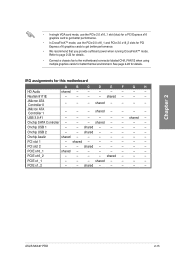
... card mode, use the PCIe 2.0 x16_1 slot (blue) for a PCI Express x16 graphics card to get better performance. • We recommend that you provide sufficient power when running CrossFireX™ mode. shared - - - Onchip SATA Controller - - - shared - - - - - PCIE x16_1 shared - - - - - - - shared - - - - PCIE x1_2 - - PCIE x16_2 - - - - shared - ... 1 - - - shared - - - - shared - shared - - - - - Onchip Azaliz shared - - - - - - - PCI slot 1 - PCI slot 2 - - shared - - - - - ASUS M5A97 PRO 2-15
... card mode, use the PCIe 2.0 x16_1 slot (blue) for a PCI Express x16 graphics card to get better performance. • We recommend that you provide sufficient power when running CrossFireX™ mode. shared - - - Onchip SATA Controller - - - shared - - - - - PCIE x16_1 shared - - - - - - - shared - - - - PCIE x1_2 - - PCIE x16_2 - - - - shared - ... 1 - - - shared - - - - shared - shared - - - - - Onchip Azaliz shared - - - - - - - PCI slot 1 - PCI slot 2 - - shared - - - - - ASUS M5A97 PRO 2-15
User Manual
Page 34
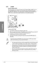
...• You do not help, remove the onboard battery and move the cap back to pins 1-2. 3. enter data. Turn OFF the computer and unplug the power cord. 2. Move the jumper cap from pins 1-2 (default) to overclocking, use the C.P.R. (CPU Parameter Recall) feature. Except when clearing the RTC RAM,...system. 2-16 Chapter 2: Hardware information For system failure due to pins 2-3. You must turn ON the computer. 4. The onboard button cell battery powers the RAM data in CMOS. Removing the cap will cause system boot failure! • If the steps above do not need to clear the...
...• You do not help, remove the onboard battery and move the cap back to pins 1-2. 3. enter data. Turn OFF the computer and unplug the power cord. 2. Move the jumper cap from pins 1-2 (default) to overclocking, use the C.P.R. (CPU Parameter Recall) feature. Except when clearing the RTC RAM,...system. 2-16 Chapter 2: Hardware information For system failure due to pins 2-3. You must turn ON the computer. 4. The onboard button cell battery powers the RAM data in CMOS. Removing the cap will cause system boot failure! • If the steps above do not need to clear the...
User Manual
Page 35
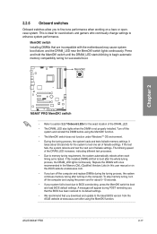
...-tune performance when working on the computer. switch Installing DIMMs that you download and update to the latest BIOS version from the ASUS website at www.asus.com. • If you that the BIOS has been restored to memory tuning requirement, the system automatically reboots when each timing...Lists) in this user manual or on the ASUS website at www.asus.com after turning on a bare or opencase system. ASUS M5A97 PRO 2-17 This is ideal for the system to BIOS overclocking, press the MemOK! Turn off the computer and unplug the power cord for about 30 seconds for overclockers and...
...-tune performance when working on the computer. switch Installing DIMMs that you download and update to the latest BIOS version from the ASUS website at www.asus.com. • If you that the BIOS has been restored to memory tuning requirement, the system automatically reboots when each timing...Lists) in this user manual or on the ASUS website at www.asus.com after turning on a bare or opencase system. ASUS M5A97 PRO 2-17 This is ideal for the system to BIOS overclocking, press the MemOK! Turn off the computer and unplug the power cord for about 30 seconds for overclockers and...

User Manual
Page 36
... or in any motherboard component. The illustration below shows the location of CPU, DRAM, VGA card, and HDD indicate key components status during POST (Power-on Self Test). 2.2.7 Onboard LEDs 1. Chapter 2 2-18 Chapter 2: Hardware information If an error is solved. This user-friendly design provides an ... device will continue lighting until the problem is found , the LED next to locate the root problem within a second. 2. Standby Power LED The motherboard comes with a standby power LED. The green LED lights up to indicate that you should shut down the system and unplug the...
... or in any motherboard component. The illustration below shows the location of CPU, DRAM, VGA card, and HDD indicate key components status during POST (Power-on Self Test). 2.2.7 Onboard LEDs 1. Chapter 2 2-18 Chapter 2: Hardware information If an error is solved. This user-friendly design provides an ... device will continue lighting until the problem is found , the LED next to locate the root problem within a second. 2. Standby Power LED The motherboard comes with a standby power LED. The green LED lights up to indicate that you should shut down the system and unplug the...

User Manual
Page 40
... the fan connectors on the fan connectors! • The CPU_FAN connector supports the CPU fan of maximum 1A (12 W) fan power. • Only the CPU_FAN, CHA_FAN 1 and CHA_FAN 2 connectors support the ASUS FAN Xpert feature. • If you plug the rear chassis fan cable to the fan connectors. Do not place jumper...
... the fan connectors on the fan connectors! • The CPU_FAN connector supports the CPU fan of maximum 1A (12 W) fan power. • Only the CPU_FAN, CHA_FAN 1 and CHA_FAN 2 connectors support the ASUS FAN Xpert feature. • If you plug the rear chassis fan cable to the fan connectors. Do not place jumper...
User Manual
Page 41
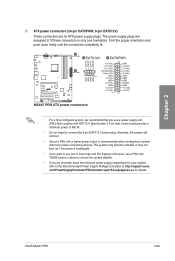
.... • Use of 450 W. • Do not forget to the Recommended Power Supply Wattage Calculator at http://support.asus. The power supply plugs are uncertain about the minimum power supply requirement for your system, refer to connect the 8-pin EATX12 V power plug; com/PowerSupplyCalculator/PSCalculator.aspx?SLanguage=en-us for ATX power supply plugs. ASUS M5A97 PRO 2-23 Chapter 2 7.
.... • Use of 450 W. • Do not forget to the Recommended Power Supply Wattage Calculator at http://support.asus. The power supply plugs are uncertain about the minimum power supply requirement for your system, refer to connect the 8-pin EATX12 V power plug; com/PowerSupplyCalculator/PSCalculator.aspx?SLanguage=en-us for ATX power supply plugs. ASUS M5A97 PRO 2-23 Chapter 2 7.
User Manual
Page 42
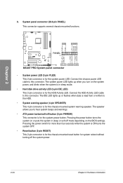
...system in sleep mode. • Hard disk drive activity LED (2-pin IDE_LED) This 2-pin connector is for the HDD Activity LED. Pressing the power switch for more than four seconds while the system is ON turns the system OFF. • Reset button (2-pin RESET) This 2-pin connector... is for the chassis-mounted reset button for the system power button. 8. System panel connector (20-8 pin PANEL) This connector supports several chassis-mounted functions. The system power LED lights up or flashes when data is for system reboot without turning off button (2-...
...system in sleep mode. • Hard disk drive activity LED (2-pin IDE_LED) This 2-pin connector is for the HDD Activity LED. Pressing the power switch for more than four seconds while the system is ON turns the system OFF. • Reset button (2-pin RESET) This 2-pin connector... is for the chassis-mounted reset button for the system power button. 8. System panel connector (20-8 pin PANEL) This connector supports several chassis-mounted functions. The system power LED lights up or flashes when data is for system reboot without turning off button (2-...

User Manual
Page 43
Chapter 2 2.3 Building your computer system 2.3.1 Additional tools and components to build a PC system 1 bag of screws Philips (cross) screwdriver PC chassis Power supply unit AMD AM3+ CPU AMD AM3+ compatible CPU Fan DIMM SATA hard disk drive SATA optical disc drive (optional) Graphics card (optional) The tools and components in the table above are not included in the motherboard package. ASUS M5A97 PRO 2-25
Chapter 2 2.3 Building your computer system 2.3.1 Additional tools and components to build a PC system 1 bag of screws Philips (cross) screwdriver PC chassis Power supply unit AMD AM3+ CPU AMD AM3+ compatible CPU Fan DIMM SATA hard disk drive SATA optical disc drive (optional) Graphics card (optional) The tools and components in the table above are not included in the motherboard package. ASUS M5A97 PRO 2-25


