User Manual
Page 8
...the devices are unplugged before relocating the system. • When adding or removing devices to or from the system, ensure that your power supply is broken, do not try to fix it may become wet. • Place the product on it, carefully read all the manuals... the REACH (Registration, Evaluation, Authorisation, and Restriction of Chemicals) regulatory framework, we published the chemical substances in our products at ASUS REACH website at http://csr.asus.com/english/REACH.htm. If you add a device. • Before connecting or removing signal cables from connectors, slots, sockets ...
...the devices are unplugged before relocating the system. • When adding or removing devices to or from the system, ensure that your power supply is broken, do not try to fix it may become wet. • Place the product on it, carefully read all the manuals... the REACH (Registration, Evaluation, Authorisation, and Restriction of Chemicals) regulatory framework, we published the chemical substances in our products at ASUS REACH website at http://csr.asus.com/english/REACH.htm. If you add a device. • Before connecting or removing signal cables from connectors, slots, sockets ...
User Manual
Page 18
... stylish heatsink features a 0-dB thermal solution that allows you to restore corrupted BIOS data from switching power supply unit (PSU). ASUS Quiet Thermal Solutions ASUS Quiet Thermal solution makes system more stable and enhances the overclocking capability. Fan Xpert ASUS Fan Xpert intelligently allows you to fine-tune the VCore / VDDNB voltage in 0.003125V steps...
... stylish heatsink features a 0-dB thermal solution that allows you to restore corrupted BIOS data from switching power supply unit (PSU). ASUS Quiet Thermal Solutions ASUS Quiet Thermal solution makes system more stable and enhances the overclocking capability. Fan Xpert ASUS Fan Xpert intelligently allows you to fine-tune the VCore / VDDNB voltage in 0.003125V steps...
User Manual
Page 19
...ASUS M5A88-M 2-1 Failure to do so may cause severe damage to avoid touching the ICs on them. • Whenever you uninstall any component, place it on a grounded antistatic pad or in the bag that came with the component. • Before you install or remove any component, ensure that the ATX power supply... is switched off or the power cord is detached from the power supply. Chapter 2: Chapter 2 Hardware information 2.1 Before you proceed Take note of the following precautions before...
...ASUS M5A88-M 2-1 Failure to do so may cause severe damage to avoid touching the ICs on them. • Whenever you uninstall any component, place it on a grounded antistatic pad or in the bag that came with the component. • Before you install or remove any component, ensure that the ATX power supply... is switched off or the power cord is detached from the power supply. Chapter 2: Chapter 2 Hardware information 2.1 Before you proceed Take note of the following precautions before...

User Manual
Page 30
... the socket. DIMM notch 2 1 Unlocked retaining clip 1 DIMM slot key A DIMM is keyed with extra force. 1 2. Simultaneously press the retaining clip outward to unplug the power supply before adding or removing DIMMs or other system components. Remove the DIMM from the socket. 2-12 Chapter 2: Hardware information Hold the DIMM by pressing the...
... the socket. DIMM notch 2 1 Unlocked retaining clip 1 DIMM slot key A DIMM is keyed with extra force. 1 2. Simultaneously press the retaining clip outward to unplug the power supply before adding or removing DIMMs or other system components. Remove the DIMM from the socket. 2-12 Chapter 2: Hardware information Hold the DIMM by pressing the...

User Manual
Page 46
... power supply requirement for ATX power supply plugs. ATX power connectors (24-pin EATXPWR; 4-pin ATX12V) These connectors are designed to connect the 4-pin ATX12 V power plug; ATX12V EATXPWR +12V DC +12V DC M5A88-M GND GND +3 Volts +12 Volts +12 Volts +5V Standby PIN 1 Power ... these connectors in only one orientation. asus.com/PowerSupplyCalculator/PSCalculator.aspx?SLanguage=en-us for details. 8. Chapter 2 2-28 Chapter 2: Hardware information The power supply plugs are for your system, refer to the Recommended Power Supply Wattage Calculator at http://support. Find ...
... power supply requirement for ATX power supply plugs. ATX power connectors (24-pin EATXPWR; 4-pin ATX12V) These connectors are designed to connect the 4-pin ATX12 V power plug; ATX12V EATXPWR +12V DC +12V DC M5A88-M GND GND +3 Volts +12 Volts +12 Volts +5V Standby PIN 1 Power ... these connectors in only one orientation. asus.com/PowerSupplyCalculator/PSCalculator.aspx?SLanguage=en-us for details. 8. Chapter 2 2-28 Chapter 2: Hardware information The power supply plugs are for your system, refer to the Recommended Power Supply Wattage Calculator at http://support. Find ...
User Manual
Page 47
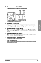
... Reset Ground M5A88-M IDE_LED PWRSW RESET * Requires an ATX power supply M5A88-M System panel connector • System power LED (2-pin PLED) This 2-pin connector is read from or written to hear system beeps and warnings. • ATX power button/soft-off the system power. Connect the chassis power LED cable to... you turn on the system power, and blinks when the system is in sleep mode. • Hard disk drive activity LED (2-pin IDE_LED) This 2-pin connector is for the chassis-mounted reset button for the chassis-mounted system warning speaker. ASUS M5A88-M 2-29 Chapter 2 9. System...
... Reset Ground M5A88-M IDE_LED PWRSW RESET * Requires an ATX power supply M5A88-M System panel connector • System power LED (2-pin PLED) This 2-pin connector is read from or written to hear system beeps and warnings. • ATX power button/soft-off the system power. Connect the chassis power LED cable to... you turn on the system power, and blinks when the system is in sleep mode. • Hard disk drive activity LED (2-pin IDE_LED) This 2-pin connector is for the chassis-mounted reset button for the chassis-mounted system warning speaker. ASUS M5A88-M 2-29 Chapter 2 9. System...
User Manual
Page 50
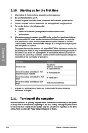
... 1. Refer to enter the BIOS Setup. At power on the devices in the following order: a. Be sure that is ON, pressing the power switch for less than four seconds lets the system enter the soft-off the computer While the system is equipped with ATX power supplies, the system LED lights up when you... turned on the power, the system may light up for more than four seconds puts the system on the screen. Turn on , hold down...
... 1. Refer to enter the BIOS Setup. At power on the devices in the following order: a. Be sure that is ON, pressing the power switch for less than four seconds lets the system enter the soft-off the computer While the system is equipped with ATX power supplies, the system LED lights up when you... turned on the power, the system may light up for more than four seconds puts the system on the screen. Turn on , hold down...

User Manual
Page 79
Turning an external modem off and then back on the system. Chapter 3 ASUS M5A88-M 3-29 Power On From S5 By PME# [Disabled] [Disabled] Disables the PME to wake up from S5 by PCI/PCIE devices. [Enabled] Allows you to use specific ... the computer and applications are fully running. This feature requires an ATX power supply that provides at least 1A on . This feature requires an ATX power supply that provides at least 1A on the system through a PCI/PCIE LAN or modem card. Power On From S5 By Ring [Disabled] [Disabled] Disables to [Enabled], the items...
Turning an external modem off and then back on the system. Chapter 3 ASUS M5A88-M 3-29 Power On From S5 By PME# [Disabled] [Disabled] Disables the PME to wake up from S5 by PCI/PCIE devices. [Enabled] Allows you to use specific ... the computer and applications are fully running. This feature requires an ATX power supply that provides at least 1A on . This feature requires an ATX power supply that provides at least 1A on the system through a PCI/PCIE LAN or modem card. Power On From S5 By Ring [Disabled] [Disabled] Disables to [Enabled], the items...


