
User Manual
Page 19
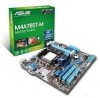
...audio connector (10-1 pin AAFP) 1-27 ASUS M4A785T-M 1-7 SATA connectors (7-pin SATA1-6) 1-24 1-8 10. CPU Socket AM3 4. IDE connector (40-1 pin PRI_IDE) Page Connectors/Jumpers/Slots/LED 1-28 8. Digital audio connector (4-1 pin SPDIF_OUT) 1-27 1-23 14. DDR3 DIMM slots 5. System panel connector (20-8... pin PANEL) 1-25 1-11 11. 1.5.3 Motherboard layout 1.5.4 Layout contents Connectors/Jumpers/Slots/LED 1. CPU and chassis fan connectors (4-pin CPU_FAN and 3-pin CHA_FAN) 2. LPT connector (26-1 pin LPT) 7. Clear RTC RAM (3-pin...
...audio connector (10-1 pin AAFP) 1-27 ASUS M4A785T-M 1-7 SATA connectors (7-pin SATA1-6) 1-24 1-8 10. CPU Socket AM3 4. IDE connector (40-1 pin PRI_IDE) Page Connectors/Jumpers/Slots/LED 1-28 8. Digital audio connector (4-1 pin SPDIF_OUT) 1-27 1-23 14. DDR3 DIMM slots 5. System panel connector (20-8... pin PANEL) 1-25 1-11 11. 1.5.3 Motherboard layout 1.5.4 Layout contents Connectors/Jumpers/Slots/LED 1. CPU and chassis fan connectors (4-pin CPU_FAN and 3-pin CHA_FAN) 2. LPT connector (26-1 pin LPT) 7. Clear RTC RAM (3-pin...

User Manual
Page 30
... the system so the BIOS can clear the CMOS memory of date, time, and system setup parameters by erasing the CMOS RTC RAM data. 1.9 Jumpers 1. To erase the RTC RAM: 1. Plug the power cord and turn ON the computer. 4. Move the jumper cap from pins 1-2 (default) to overclocking. After clearing the... CMOS, reinstall the battery. • You do not help, remove the onboard battery and move the cap back to clear the CMOS RTC RAM data. Keep the cap on CLRTC jumper default position. Shut down the key during the boot process and enter BIOS setup to default values. 1-18...
... the system so the BIOS can clear the CMOS memory of date, time, and system setup parameters by erasing the CMOS RTC RAM data. 1.9 Jumpers 1. To erase the RTC RAM: 1. Plug the power cord and turn ON the computer. 4. Move the jumper cap from pins 1-2 (default) to overclocking. After clearing the... CMOS, reinstall the battery. • You do not help, remove the onboard battery and move the cap back to clear the CMOS RTC RAM data. Keep the cap on CLRTC jumper default position. Shut down the key during the boot process and enter BIOS setup to default values. 1-18...

User Manual
Page 46
... configuration of the SPI chip. They may not exactly match what you see on . Entering BIOS Setup at startup To enter BIOS Setup at www.asus.com to download the latest BIOS file for this program. Even if you are not prompted to use the Setup program, you can change the... the reset button on the system chassis. • Press the power button to turn the system off then back on your screen. • Visit the ASUS website at startup: • Press during the Power-On Self-Test (POST) to enter the Setup utility; See section 2.8 Exit Menu. • The BIOS setup...
... configuration of the SPI chip. They may not exactly match what you see on . Entering BIOS Setup at startup To enter BIOS Setup at www.asus.com to download the latest BIOS file for this program. Even if you are not prompted to use the Setup program, you can change the... the reset button on the system chassis. • Press the power button to turn the system off then back on your screen. • Visit the ASUS website at startup: • Press during the Power-On Self-Test (POST) to enter the Setup utility; See section 2.8 Exit Menu. • The BIOS setup...

User Manual
Page 61
...'DEL' Message Display [Enabled] When this item is set to [Enabled], the system waits for the F1 key to erase the RTC RAM. Confirm the password when prompted. The Supervisor Password item on state for information on how to be pressed when error occurs. In the ... the supervisor password. User Access Level [Full Access] This item allows you successfully set a password, this item to display the configuration options. ASUS M4A785T-M 2-19 Select an item then press to set a Supervisor Password: 1. After you set your BIOS password, you forget your password. Change...
...'DEL' Message Display [Enabled] When this item is set to [Enabled], the system waits for the F1 key to erase the RTC RAM. Confirm the password when prompted. The Supervisor Password item on state for information on how to be pressed when error occurs. In the ... the supervisor password. User Access Level [Full Access] This item allows you successfully set a password, this item to display the configuration options. ASUS M4A785T-M 2-19 Select an item then press to set a Supervisor Password: 1. After you set your BIOS password, you forget your password. Change...

User Manual
Page 64
... values. Select OK to discard any changes and load the previously saved values. An onboard backup battery sustains the CMOS RAM so it stays on the Setup menus. F1F010kekyeycacnanbebeusuesded fofrorthtihsisopoepreartaitoino.n. If you made and restore the previously saved values. When you...make other than System Date, System Time, and Password, the BIOS asks for a confirmation before saving the values to the non-volatile RAM. 2-22 Chapter 2: BIOS information Load Setup Defaults This option allows you press , a confirmation window appears. Exit & Pressing does ...
... values. Select OK to discard any changes and load the previously saved values. An onboard backup battery sustains the CMOS RAM so it stays on the Setup menus. F1F010kekyeycacnanbebeusuesded fofrorthtihsisopoepreartaitoino.n. If you made and restore the previously saved values. When you...make other than System Date, System Time, and Password, the BIOS asks for a confirmation before saving the values to the non-volatile RAM. 2-22 Chapter 2: BIOS information Load Setup Defaults This option allows you press , a confirmation window appears. Exit & Pressing does ...


