
User Manual
Page 7
...is broken, do not try to change system settings through the BIOS Setup menus. If possible, disconnect all power cables from connectors, slots, sockets and circuitry. • Avoid dust, humidity, and temperature extremes. If you are not sure about the voltage of the BIOS parameters are... If the power supply is organized This guide contains the following parts: • Chapter 1: Product introduction This chapter describes the features of the motherboard and the new technology it supports. • Chapter 2: BIOS setup This chapter tells how to fix it , carefully read all cables are ...
...is broken, do not try to change system settings through the BIOS Setup menus. If possible, disconnect all power cables from connectors, slots, sockets and circuitry. • Avoid dust, humidity, and temperature extremes. If you are not sure about the voltage of the BIOS parameters are... If the power supply is organized This guide contains the following parts: • Chapter 1: Product introduction This chapter describes the features of the motherboard and the new technology it supports. • Chapter 2: BIOS setup This chapter tells how to fix it , carefully read all cables are ...

User Manual
Page 9
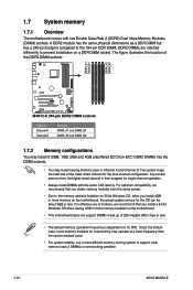
...OS limitation, when installing total memory of less than 3GB. ASUS Noise Filtering VIA® VT6315N controller supports 2 x IEEE 1394a ports 12 x USB 2.0 ports (6 ports at midboard; 6 ports at back I/O - M4N72-E specifications summary CPU Chipset System bus Memory Multi-GPU support... Expansion slots Storage LAN Audio IEEE 1394 USB Phenom™ X4 / Phenom™ X3 / Athlon™ X2 / Athlon™ / Sempron™ processors (socket AM2+/AM2) Compatible with Phenom™...
...OS limitation, when installing total memory of less than 3GB. ASUS Noise Filtering VIA® VT6315N controller supports 2 x IEEE 1394a ports 12 x USB 2.0 ports (6 ports at midboard; 6 ports at back I/O - M4N72-E specifications summary CPU Chipset System bus Memory Multi-GPU support... Expansion slots Storage LAN Audio IEEE 1394 USB Phenom™ X4 / Phenom™ X3 / Athlon™ X2 / Athlon™ / Sempron™ processors (socket AM2+/AM2) Compatible with Phenom™...

User Manual
Page 14
...X2 / Athlon™ / Sempron™ processors (socket AM2+ / AM2) The motherboard supports AMD® Socket AM2+ multi-core processors. DDR2 1066 support This motherboard supports DDR2 1066, which delivers high power efficiency and supreme overclocking ability. ASUS M4N72-E also features an extra 2 or 1-phase power...with the best platform for the supported CPU models. 1.3.2 Innovative ASUS features ASUS Power Solution ASUS 8+1 Phase Power Design To fully unleash the next-generation AM3 CPU's potential, ASUS M4N72-E motherboard has adopted the brand-new 8-phase VRM power design, which ...
...X2 / Athlon™ / Sempron™ processors (socket AM2+ / AM2) The motherboard supports AMD® Socket AM2+ multi-core processors. DDR2 1066 support This motherboard supports DDR2 1066, which delivers high power efficiency and supreme overclocking ability. ASUS M4N72-E also features an extra 2 or 1-phase power...with the best platform for the supported CPU models. 1.3.2 Innovative ASUS features ASUS Power Solution ASUS 8+1 Phase Power Design To fully unleash the next-generation AM3 CPU's potential, ASUS M4N72-E motherboard has adopted the brand-new 8-phase VRM power design, which ...

User Manual
Page 16
... off mode. The illustration below shows the location of the following precautions before you install motherboard components or change any motherboard settings. • Unplug the power cord from the wall socket before removing or plugging in the bag that came with a standby power LED that lights... or components. This is ON, in sleep mode, or in soft-off the ATX power supply and detach its power cord. 1.4 Before you proceed Take note of the onboard LED. 1-4 ASUS M4N72-E Onboard LED The motherboard comes with the component. • Before you uninstall any component, place it on...
... off mode. The illustration below shows the location of the following precautions before you install motherboard components or change any motherboard settings. • Unplug the power cord from the wall socket before removing or plugging in the bag that came with a standby power LED that lights... or components. This is ON, in sleep mode, or in soft-off the ATX power supply and detach its power cord. 1.4 Before you proceed Take note of the onboard LED. 1-4 ASUS M4N72-E Onboard LED The motherboard comes with the component. • Before you uninstall any component, place it on...

User Manual
Page 18
...1-23 1-19 1-7 1-22 1-10 1-25 1-24 1-4 1-22 1-18 1-26 1-17 1-27 1-30 1-29 1-27 1-28 1-28 1-29 1-6 ASUS M4N72-E System panel connector (20-8 pin PANEL) 13. Serial port connector (10-1 pin COM1) 17. USB device wake-up (3-pin USBPW1-4, USBPW7-10, ...(7-pin SATA1-6) 8. Digital audio connector (4-1 pin SPDIF_OUT) 19. CPU socket AM2+/AM2 5. Clear RTC RAM (CLRTC) 14. Optical drive audio in connector (4-pin CD) 20. 1.5.3 Motherboard layout 1.5.4 Layout contents Connectors/Jumpers/Slots 1. ATX power connectors (24-pin EATXPWR, 4-pin ATX12V) 3. DDR2 DIMM slots...
...1-23 1-19 1-7 1-22 1-10 1-25 1-24 1-4 1-22 1-18 1-26 1-17 1-27 1-30 1-29 1-27 1-28 1-28 1-29 1-6 ASUS M4N72-E System panel connector (20-8 pin PANEL) 13. Serial port connector (10-1 pin COM1) 17. USB device wake-up (3-pin USBPW1-4, USBPW7-10, ...(7-pin SATA1-6) 8. Digital audio connector (4-1 pin SPDIF_OUT) 19. CPU socket AM2+/AM2 5. Clear RTC RAM (CLRTC) 14. Optical drive audio in connector (4-pin CD) 20. 1.5.3 Motherboard layout 1.5.4 Layout contents Connectors/Jumpers/Slots 1. ATX power connectors (24-pin EATXPWR, 4-pin ATX12V) 3. DDR2 DIMM slots...
User Manual
Page 19
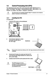
...an Opteron™ processor on the motherboard. 2. Small triangle Gold triangle Chapter 1: Product introduction 1-7 Carefully insert the CPU into the socket to a 90°-100° angle. Position the CPU above the socket such that the socket lever is not compatible with a ...small triangle. 4. Locate the CPU socket on this motherboard. 1.6.1 Installing the CPU To install a CPU: 1. 1.6 Central Processing Unit (CPU) The motherboard comes with a CPU socket designed for AMD® AM3...
...an Opteron™ processor on the motherboard. 2. Small triangle Gold triangle Chapter 1: Product introduction 1-7 Carefully insert the CPU into the socket to a 90°-100° angle. Position the CPU above the socket such that the socket lever is not compatible with a ...small triangle. 4. Locate the CPU socket on this motherboard. 1.6.1 Installing the CPU To install a CPU: 1. 1.6 Central Processing Unit (CPU) The motherboard comes with a CPU socket designed for AMD® AM3...

User Manual
Page 20
...motherboard. Connect the CPU fan cable to indicate that the heatsink fits properly on the retention module base. • The retention module base is properly applied to secure the CPU. When the CPU is locked. 6. CPU Fan CPU Heatsink Retention bracket Retention bracket lock Retention Module Base 1-8 ASUS M4N72...-E Place the heatsink on top of the installed CPU, making sure that it is in place, push down the socket lever to the CPU heatsink or CPU before you use only AMD-...
...motherboard. Connect the CPU fan cable to indicate that the heatsink fits properly on the retention module base. • The retention module base is properly applied to secure the CPU. When the CPU is locked. 6. CPU Fan CPU Heatsink Retention bracket Retention bracket lock Retention Module Base 1-8 ASUS M4N72...-E Place the heatsink on top of the installed CPU, making sure that it is in place, push down the socket lever to the CPU heatsink or CPU before you use only AMD-...
User Manual
Page 22
...channel is dependent on a DDR DIMM socket. Under the default state, some memory modules for overclocking may install varying memory sizes in Channel A and Channel B. For effective use a more memory on the motherboard. • This motherboard does not support DIMMs made up of...motherboard, the actual usable memory for single-channel operation. • Always install DIMMs with two Double Data Rate 2 (DDR2) Dual Inline Memory Modules (DIMM) sockets. Any excess memory from the same vendor. • Due to support a full memory load (4 DIMMs) or overclocking condition. 1-10 ASUS M4N72...
...channel is dependent on a DDR DIMM socket. Under the default state, some memory modules for overclocking may install varying memory sizes in Channel A and Channel B. For effective use a more memory on the motherboard. • This motherboard does not support DIMMs made up of...motherboard, the actual usable memory for single-channel operation. • Always install DIMMs with two Double Data Rate 2 (DDR2) Dual Inline Memory Modules (DIMM) sockets. Any excess memory from the same vendor. • Due to support a full memory load (4 DIMMs) or overclocking condition. 1-10 ASUS M4N72...

User Manual
Page 23
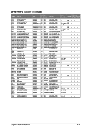
... N2TU 51280CE-BD 7YDI2 Heat-Sink Package Heat-Sink Package Heat-Sink Package Heat-Sink Package 5 5 6 5-5-5-15 (800-5-5-5-15) 5-5-5-15 6 5-5-5-15 5-5-5-15 5-5-5-15 5-5-5-15 DIMM socket Voltage support (Optional) A* B* C* ••• ••• 2.1 • • • 2.0 • • • ••• 2.0-2.1 • • •... installed, all DIMMs run at 800Mhz frequency by default for system stability. Chapter 1: Product introduction 1-11 M4N72-E Motherboard Qualified Vendors Lists (QVL) DDR2-1066MHz capability Vendor Part No.
... N2TU 51280CE-BD 7YDI2 Heat-Sink Package Heat-Sink Package Heat-Sink Package Heat-Sink Package 5 5 6 5-5-5-15 (800-5-5-5-15) 5-5-5-15 6 5-5-5-15 5-5-5-15 5-5-5-15 5-5-5-15 DIMM socket Voltage support (Optional) A* B* C* ••• ••• 2.1 • • • 2.0 • • • ••• 2.0-2.1 • • •... installed, all DIMMs run at 800Mhz frequency by default for system stability. Chapter 1: Product introduction 1-11 M4N72-E Motherboard Qualified Vendors Lists (QVL) DDR2-1066MHz capability Vendor Part No.
User Manual
Page 25
...-25F SAMSUNG K4T51083QG SAMSUNG K4T1G084QQ SAMSUNG K4T1G084QQ(ECC) SAMSUNG K4T51083QG SAMSUNG K4T1G084QQ(ECC) SAMSUNG K4T1G084QQ SAMSUNG K4T2G084QA-HCF7 Heat-Sink Package Timing Dimm (Bios) DIMM socket Voltage support (Optional) A* B* C* • 5 1.8 • • 5 1.8 • • 3-4-4 (800-5- 2.35 • 5-5-15) 5-4-4 1.8 • • • 5 1.80 • • • 5-6-6 (800-5- 1.8 • • • 5-5-15) 5 •...
...-25F SAMSUNG K4T51083QG SAMSUNG K4T1G084QQ SAMSUNG K4T1G084QQ(ECC) SAMSUNG K4T51083QG SAMSUNG K4T1G084QQ(ECC) SAMSUNG K4T1G084QQ SAMSUNG K4T2G084QA-HCF7 Heat-Sink Package Timing Dimm (Bios) DIMM socket Voltage support (Optional) A* B* C* • 5 1.8 • • 5 1.8 • • 3-4-4 (800-5- 2.35 • 5-5-15) 5-4-4 1.8 • • • 5 1.80 • • • 5-6-6 (800-5- 1.8 • • • 5-5-15) 5 •...
User Manual
Page 26
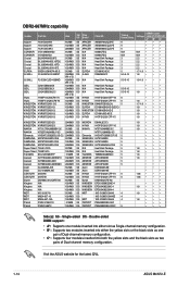
... capability Vendor Part No. Single-sided DS - Visit the ASUS website for the latest QVL. 1-14 ASUS M4N72-E AM4B5708JQJS7E AM4B5808CQJS7E AM4B5808CQJS7E 64M8CFEG 64M8CFEG Heat-Sink Package Heat-Sink Package Heat-Sink Package Heat-Sink Package E5108AE-6E-E D264M8GCF Timing Dimm (Bios) 5 5 5 N/A N/A 3 3 3 3 5 5-5-5-15 Voltage N/A N/A 2.2 2.2 2.2 2.2 1.7-1.9 1.8 DIMM socket support (Optional) A* B* C* • • • • • • •...
... capability Vendor Part No. Single-sided DS - Visit the ASUS website for the latest QVL. 1-14 ASUS M4N72-E AM4B5708JQJS7E AM4B5808CQJS7E AM4B5808CQJS7E 64M8CFEG 64M8CFEG Heat-Sink Package Heat-Sink Package Heat-Sink Package Heat-Sink Package E5108AE-6E-E D264M8GCF Timing Dimm (Bios) 5 5 5 N/A N/A 3 3 3 3 5 5-5-5-15 Voltage N/A N/A 2.2 2.2 2.2 2.2 1.7-1.9 1.8 DIMM socket support (Optional) A* B* C* • • • • • • •...
User Manual
Page 27
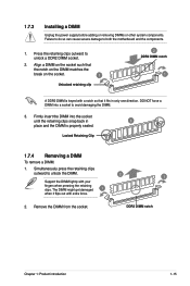
...it fits in 3 place and the DIMM is keyed with a notch so that the notch on the DIMM matches the break on the socket such that it flips out with your fingers when pressing the retaining clips. 1.7.3 Installing a DIMM Unplug the power supply before adding or ...removing DIMMs or other system components. Press the retaining clips outward to both the motherboard and the components. 1. Support the DIMM lightly with extra force. 2. Align a DIMM on the socket. 1 Unlocked retaining clip 2 DDR2 DIMM notch 1 A DDR2 DIMM is properly seated. Remove the...
...it fits in 3 place and the DIMM is keyed with a notch so that the notch on the DIMM matches the break on the socket such that it flips out with your fingers when pressing the retaining clips. 1.7.3 Installing a DIMM Unplug the power supply before adding or ...removing DIMMs or other system components. Press the retaining clips outward to both the motherboard and the components. 1. Support the DIMM lightly with extra force. 2. Align a DIMM on the socket. 1 Unlocked retaining clip 2 DDR2 DIMM notch 1 A DDR2 DIMM is properly seated. Remove the...


