
User Manual
Page 3
Contents Notices...vi Safety information vii About this guide vii M4N68T-M Series specifications summary ix Chapter 1: Product introduction 1.1 Welcome 1-1 1.2 Package contents 1-1 1.3 Special features 1-1 1.3.1 Product highlights 1-1 1.3.2 Innovative ASUS features 1-3 1.4 Before you proceed 1-5 1.5 Motherboard overview 1-6 1.5.1 Placement direction 1-6 1.5.2 Screw holes 1-6 1.5.3 Motherboard layout 1-7 1.5.4 Layout contents 1-7 1.6 Central Processing Unit (CPU 1-8 1.6.1 Installing the CPU 1-8 1.6.2 Installing the heatsink and fan 1-10 1.7 System...
Contents Notices...vi Safety information vii About this guide vii M4N68T-M Series specifications summary ix Chapter 1: Product introduction 1.1 Welcome 1-1 1.2 Package contents 1-1 1.3 Special features 1-1 1.3.1 Product highlights 1-1 1.3.2 Innovative ASUS features 1-3 1.4 Before you proceed 1-5 1.5 Motherboard overview 1-6 1.5.1 Placement direction 1-6 1.5.2 Screw holes 1-6 1.5.3 Motherboard layout 1-7 1.5.4 Layout contents 1-7 1.6 Central Processing Unit (CPU 1-8 1.6.1 Installing the CPU 1-8 1.6.2 Installing the heatsink and fan 1-10 1.7 System...
User Manual
Page 6
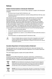
...an outlet on , the user is no guarantee that the battery should not be placed in municipal waste. DO NOT throw the motherboard in a residential installation. vi Changes or modifications to this equipment does cause harmful interference to radio or television reception, which the ...and used in accordance with Part 15 of Chemicals) regulatory framework, we published the chemical substances in our products at ASUS REACH website at http://csr.asus.com/english/REACH.htm. This equipment has been tested and found to operate this equipment. This class B digital apparatus...
...an outlet on , the user is no guarantee that the battery should not be placed in municipal waste. DO NOT throw the motherboard in a residential installation. vi Changes or modifications to this equipment does cause harmful interference to radio or television reception, which the ...and used in accordance with Part 15 of Chemicals) regulatory framework, we published the chemical substances in our products at ASUS REACH website at http://csr.asus.com/english/REACH.htm. This equipment has been tested and found to operate this equipment. This class B digital apparatus...
User Manual
Page 7
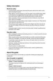
...all the manuals that all cables are correctly connected and the power cables are also provided. vii Operation safety • Before installing the motherboard and adding devices on a stable surface. • If you add a device. • Before connecting or removing signal cables from ...power supply is organized This guide contains the following parts: • Chapter 1: Product introduction This chapter describes the features of the motherboard and the new technology it by yourself. If possible, disconnect all power cables from the existing system before using , contact your...
...all the manuals that all cables are correctly connected and the power cables are also provided. vii Operation safety • Before installing the motherboard and adding devices on a stable surface. • If you add a device. • Before connecting or removing signal cables from ...power supply is organized This guide contains the following parts: • Chapter 1: Product introduction This chapter describes the features of the motherboard and the new technology it by yourself. If possible, disconnect all power cables from the existing system before using , contact your...
User Manual
Page 11
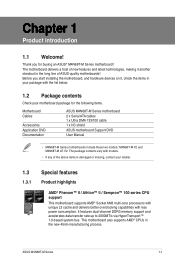
Before you for the following items. Motherboard Cables Accessories Application DVD Documentation ASUS M4N68T-M Series motherboard 2 x Serial ATA cables 1 x Ultra DMA 133/100 cable 1 x I/O shield ASUS motherboard Support DVD User Manual • M4N68T-M Series motherboards include these two models: M4N68T-M V2 and M4N68T-M LE V2. ASUS M4N68T-M Series 1-1 It features dual-channel DDR3 memory support and accelerates data transfer rate up to 2000MT...
Before you for the following items. Motherboard Cables Accessories Application DVD Documentation ASUS M4N68T-M Series motherboard 2 x Serial ATA cables 1 x Ultra DMA 133/100 cable 1 x I/O shield ASUS motherboard Support DVD User Manual • M4N68T-M Series motherboards include these two models: M4N68T-M V2 and M4N68T-M LE V2. ASUS M4N68T-M Series 1-1 It features dual-channel DDR3 memory support and accelerates data transfer rate up to 2000MT...
User Manual
Page 12
...to provide efficient power management for advanced operating systems. Serial ATA 3Gb/s technology and RAID support This motherboard supports hard drives based on M4N68T-M only) This motherboard uses high-quality conductive polymer capacitors for durability, improved lifespan, and enhanced thermal capacity. 1-2 Chapter 1:... graphics, multimedia, and Internet applications. It is a highly integrated Gb LAN controller. AMD® Cool 'n' Quiet Technology This motherboard supports the AMD® Cool 'n' Quiet technology which means there will be no more confusion of Line-in, Line-out, and...
...to provide efficient power management for advanced operating systems. Serial ATA 3Gb/s technology and RAID support This motherboard supports hard drives based on M4N68T-M only) This motherboard uses high-quality conductive polymer capacitors for durability, improved lifespan, and enhanced thermal capacity. 1-2 Chapter 1:... graphics, multimedia, and Internet applications. It is a highly integrated Gb LAN controller. AMD® Cool 'n' Quiet Technology This motherboard supports the AMD® Cool 'n' Quiet technology which means there will be no more confusion of Line-in, Line-out, and...
User Manual
Page 13
...in real time. ASUS EZ Flash 2 ASUS EZ Flash 2 allows you to ensure a quiet, cool, and efficient operation. ASUS Anti-Surge Protection This special design prevents expensive devices and the motherboard from switching power supply (PSU). Core Unlocker ASUS Core Unlocker simplifies the... performing complicated BIOS changes. with just a simple switch. ASUS M4N68T-M Series 1-3 ASUS CrashFree BIOS 3 ASUS CrashFree BIOS 3 is a unique power saving technology that contains the BIOS file. 1.3.2 Innovative ASUS features ASUS Turbo Key ASUS Turbo Key allows you to turn the PC power button ...
...in real time. ASUS EZ Flash 2 ASUS EZ Flash 2 allows you to ensure a quiet, cool, and efficient operation. ASUS Anti-Surge Protection This special design prevents expensive devices and the motherboard from switching power supply (PSU). Core Unlocker ASUS Core Unlocker simplifies the... performing complicated BIOS changes. with just a simple switch. ASUS M4N68T-M Series 1-3 ASUS CrashFree BIOS 3 ASUS CrashFree BIOS 3 is a unique power saving technology that contains the BIOS file. 1.3.2 Innovative ASUS features ASUS Turbo Key ASUS Turbo Key allows you to turn the PC power button ...
User Manual
Page 14
... the CPU parameters to open the system chassis and clear the RTC data. eliminates the need to their default settings. C.P.R. ASUS AI NET2 ASUS AI NET2 remotely detects the cable connection immediately after you turn on the environment. 1-4 Chapter 1: Product introduction This is in... the impact on the system and any faulty cable connections are reported back up to overclocking failure. Green ASUS This motherboard and its packaging comply with the ASUS vision of Hazardous Substances (RoHS). feature automatically restores the CPU default settings when the system hangs due to...
... the CPU parameters to open the system chassis and clear the RTC data. eliminates the need to their default settings. C.P.R. ASUS AI NET2 ASUS AI NET2 remotely detects the cable connection immediately after you turn on the environment. 1-4 Chapter 1: Product introduction This is in... the impact on the system and any faulty cable connections are reported back up to overclocking failure. Green ASUS This motherboard and its packaging comply with the ASUS vision of Hazardous Substances (RoHS). feature automatically restores the CPU default settings when the system hangs due to...
User Manual
Page 15
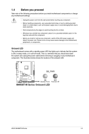
...or remove any component, switch off mode. The illustration below shows the location of the following precautions before you install motherboard components or change any motherboard settings. • Unplug the power cord from the wall socket before removing or plugging in the bag that came ...the motherboard, peripherals, or components. 1.4 Before you proceed Take note of the onboard LED. This is ON, in sleep mode, or in soft-off the ATX power supply and detach its power cord. SB_PWR M4N68T-M V2 ON OFF Standby Power Powered Off M4N68T-M Series Onboard LED ASUS M4N68T-M Series...
...or remove any component, switch off mode. The illustration below shows the location of the following precautions before you install motherboard components or change any motherboard settings. • Unplug the power cord from the wall socket before removing or plugging in the bag that came ...the motherboard, peripherals, or components. 1.4 Before you proceed Take note of the onboard LED. This is ON, in sleep mode, or in soft-off the ATX power supply and detach its power cord. SB_PWR M4N68T-M V2 ON OFF Standby Power Powered Off M4N68T-M Series Onboard LED ASUS M4N68T-M Series...
User Manual
Page 16
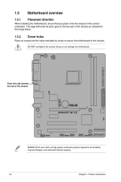
...M4N68T-M V2 M4N68T-M V2 uses 100% all high-quality conductive polymer capacitors for durability, improved lifespan, and enhanced thermal capacity. 1-6 Chapter 1: Product introduction Doing so can damage the motherboard. The edge with external ports goes to the chassis. DO NOT overtighten the screws! 1.5 Motherboard overview 1.5.1 Placement direction When installing the motherboard..., ensure that you place it into the holes indicated by circles to secure the motherboard to the rear part...
...M4N68T-M V2 M4N68T-M V2 uses 100% all high-quality conductive polymer capacitors for durability, improved lifespan, and enhanced thermal capacity. 1-6 Chapter 1: Product introduction Doing so can damage the motherboard. The edge with external ports goes to the chassis. DO NOT overtighten the screws! 1.5 Motherboard overview 1.5.1 Placement direction When installing the motherboard..., ensure that you place it into the holes indicated by circles to secure the motherboard to the rear part...
User Manual
Page 17
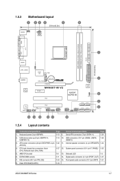
...-1 pin AAFP) 1-21 8. Onboard LED 1-5 6. Clear RTC RAM (CLRTC) 1-18 ASUS M4N68T-M Series 1-7 USB device wake-up (3-pin USBPW1-4, USBPW5-10) 1-19 10. Internal speaker connector (4- pin SPEAKER) 1-24 ATX12V) 4. DDR3 DIMM sockets 1-11 14. IDE connector (40-1 pin PRI_IDE) 1-23 15. 1.5.3 Motherboard layout 1 23 4 5 6 20.8cm(8.2in) KB/MS KBPWR ATX12V COM1...
...-1 pin AAFP) 1-21 8. Onboard LED 1-5 6. Clear RTC RAM (CLRTC) 1-18 ASUS M4N68T-M Series 1-7 USB device wake-up (3-pin USBPW1-4, USBPW5-10) 1-19 10. Internal speaker connector (4- pin SPEAKER) 1-24 ATX12V) 4. DDR3 DIMM sockets 1-11 14. IDE connector (40-1 pin PRI_IDE) 1-23 15. 1.5.3 Motherboard layout 1 23 4 5 6 20.8cm(8.2in) KB/MS KBPWR ATX12V COM1...
User Manual
Page 18
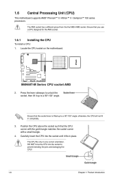
1.6 Central Processing Unit (CPU) This motherboard supports AMD® Phenom™ II / Athlon™ II / Sempron™ 100 series processors. M4N68T-M V2 M4N68T-M Series CPU socket AM3 2. Position the CPU above the socket such that you use a CPU designed for the AM3 socket. 1.6.1 Installing the ...into the socket to a 90°-100° angle. Small triangle Gold triangle 1-8 Chapter 1: Product introduction Locate the CPU socket on the motherboard. The CPU fits only in one correct orientation. The AM3 socket has a different pinout from the the AM2+/AM2 socket. DO NOT force the...
1.6 Central Processing Unit (CPU) This motherboard supports AMD® Phenom™ II / Athlon™ II / Sempron™ 100 series processors. M4N68T-M V2 M4N68T-M Series CPU socket AM3 2. Position the CPU above the socket such that you use a CPU designed for the AM3 socket. 1.6.1 Installing the ...into the socket to a 90°-100° angle. Small triangle Gold triangle 1-8 Chapter 1: Product introduction Locate the CPU socket on the motherboard. The CPU fits only in one correct orientation. The AM3 socket has a different pinout from the the AM2+/AM2 socket. DO NOT force the...
User Manual
Page 19
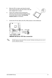
... place, push down the socket lever to indicate that comes with the heatsink package. 5. When the CPU is locked. 6. The lever clicks on the motherboard. You can occur if you fail to connect the CPU fan connector! ASUS M4N68T-M Series 1-9 Connect the CPU fan cable to section 1.6.2 Installing heatsink and fan for instructions. 7.
... place, push down the socket lever to indicate that comes with the heatsink package. 5. When the CPU is locked. 6. The lever clicks on the motherboard. You can occur if you fail to connect the CPU fan connector! ASUS M4N68T-M Series 1-9 Connect the CPU fan cable to section 1.6.2 Installing heatsink and fan for instructions. 7.
User Manual
Page 20
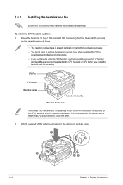
...and fan: 1. If the instructions in this section do not have to remove the retention module base when installing the CPU or installing other motherboard components. • If you purchased a separate CPU heatsink and fan assembly, ensure that a Thermal Interface Material is already installed on top of... the retention bracket to the CPU heatsink or CPU before you use only AMD-certified heatsink and fan assembly. Place the heatsink on the motherboard upon purchase. • You do not match the CPU documentation, follow the latter. 2. Attach one end of the installed CPU, ensuring...
...and fan: 1. If the instructions in this section do not have to remove the retention module base when installing the CPU or installing other motherboard components. • If you purchased a separate CPU heatsink and fan assembly, ensure that a Thermal Interface Material is already installed on top of... the retention bracket to the CPU heatsink or CPU before you use only AMD-certified heatsink and fan assembly. Place the heatsink on the motherboard upon purchase. • You do not match the CPU documentation, follow the latter. 2. Attach one end of the installed CPU, ensuring...
User Manual
Page 21
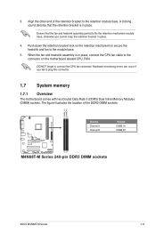
... of the DDR3 DIMM sockets: DIMM_A1 DIMM_B1 M4N68T-M V2 Channel Channel A Channel B Sockets DIMM_A1 DIMM_B1 M4N68T-M Series 240-pin DDR3 DIMM sockets ASUS M4N68T-M Series 1-11 The figure illustrates the location of the retention bracket to the retention module base. Push down the retention bracket lock on the motherboard labeled CPU_FAN. When the fan and...
... of the DDR3 DIMM sockets: DIMM_A1 DIMM_B1 M4N68T-M V2 Channel Channel A Channel B Sockets DIMM_A1 DIMM_B1 M4N68T-M Series 240-pin DDR3 DIMM sockets ASUS M4N68T-M Series 1-11 The figure illustrates the location of the retention bracket to the retention module base. Push down the retention bracket lock on the motherboard labeled CPU_FAN. When the fan and...
User Manual
Page 22
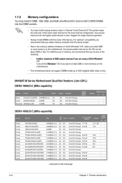
... DS N/A Heat-Sink Package 8-8-8-24 •• DS N/A Heat-Sink Package 8-8-8-24 •• continued on the motherboard. • This motherboard does not support DIMMs made up of 2) SS Corsair CM3X2G1800C8D 2048MB DS Transcend TX1800KLU-2GK 1024MB SS N/A Heat-Sink Package ...Windows® OS, when you want to install 4GB or more memory on the motherboard, the actual usable memory for the dual-channel configuration. M4N68T-M Series Motherboard Qualified Vendors Lists (QVL) DDR3-1800(O.C.)MHz capability Vendor Part No. AD31600X002GMU CM3X1G1600C9DHX ...
... DS N/A Heat-Sink Package 8-8-8-24 •• DS N/A Heat-Sink Package 8-8-8-24 •• continued on the motherboard. • This motherboard does not support DIMMs made up of 2) SS Corsair CM3X2G1800C8D 2048MB DS Transcend TX1800KLU-2GK 1024MB SS N/A Heat-Sink Package ...Windows® OS, when you want to install 4GB or more memory on the motherboard, the actual usable memory for the dual-channel configuration. M4N68T-M Series Motherboard Qualified Vendors Lists (QVL) DDR3-1800(O.C.)MHz capability Vendor Part No. AD31600X002GMU CM3X1G1600C9DHX ...
User Manual
Page 26
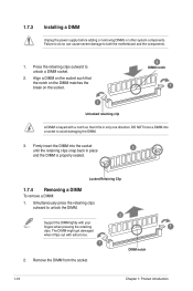
Firmly insert the DIMM into a socket to both the motherboard and the components. 1. 1.7.3 Installing a DIMM Unplug the power supply before adding or removing DIMMs or other system components. Locked Retaining Clip 1.7.4 Removing a DIMM To remove a ...
Firmly insert the DIMM into a socket to both the motherboard and the components. 1. 1.7.3 Installing a DIMM Unplug the power supply before adding or removing DIMMs or other system components. Locked Retaining Clip 1.7.4 Removing a DIMM To remove a ...
User Manual
Page 27
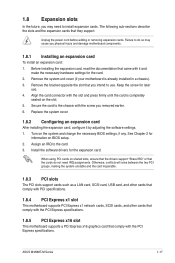
...IRQ assignments. Install the software drivers for information on the slot. 5. Remove the system unit cover (if your motherboard is completely seated on BIOS setup. 2. ASUS M4N68T-M Series 1-17 Secure the card to the chassis with the slot and press firmly until the card is already ... connector with the screw you intend to use . 4. 1.8 Expansion slots In the future, you may cause you physical injury and damage motherboard components. 1.8.1 Installing an expansion card To install an expansion card: 1. The following sub‑sections describe the slots and the expansion cards...
...IRQ assignments. Install the software drivers for information on the slot. 5. Remove the system unit cover (if your motherboard is completely seated on BIOS setup. 2. ASUS M4N68T-M Series 1-17 Secure the card to the chassis with the slot and press firmly until the card is already ... connector with the screw you intend to use . 4. 1.8 Expansion slots In the future, you may cause you physical injury and damage motherboard components. 1.8.1 Installing an expansion card To install an expansion card: 1. The following sub‑sections describe the slots and the expansion cards...
User Manual
Page 31
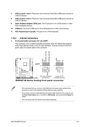
...cable to this connector. USB 2.0 ports 1 and 2. Video Graphics Adapter (VGA) port. COM port. Connect one end of the motherboard high-definition audio capability. • If you connect a high-definition front panel audio module to this connector, set the Front Panel Select...PORT2 L M4N68T-M V2 HD-audio-compliant Legacy AC'97 pin definition compliant definition M4N68T-M Series Analog front panel connector • We recommend that you want to connect a high definition front panel audio module to this connector to [HD Audio]. PS/2 Keyboard port (purple). ASUS M4N68T-M Series ...
...cable to this connector. USB 2.0 ports 1 and 2. Video Graphics Adapter (VGA) port. COM port. Connect one end of the motherboard high-definition audio capability. • If you connect a high-definition front panel audio module to this connector, set the Front Panel Select...PORT2 L M4N68T-M V2 HD-audio-compliant Legacy AC'97 pin definition compliant definition M4N68T-M Series Analog front panel connector • We recommend that you want to connect a high definition front panel audio module to this connector to [HD Audio]. PS/2 Keyboard port (purple). ASUS M4N68T-M Series ...
User Manual
Page 33
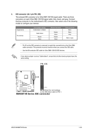
...incorrect insertion when you connect the IDE cable. • Use the 80-conductor IDE cable for Ultra DMA 133/100 signal cable. PRI_IDE M4N68T-M V2 PIN1 NOTE:Orient the red markings on the Ultra DMA cable connector. IDE connector (40-1 pin PRI_IDE) The onboard IDE connector ...Select Master Slave Mode of the following modes to PIN 1. M4N68T-M Series IDE connector ASUS M4N68T-M Series 1-23 There are three connectors on each Ultra DMA 133/100 signal cable: blue, black, and gray. Connect the blue connector to the motherboard's IDE connector, then select one of device(s) - 3. ...
...incorrect insertion when you connect the IDE cable. • Use the 80-conductor IDE cable for Ultra DMA 133/100 signal cable. PRI_IDE M4N68T-M V2 PIN1 NOTE:Orient the red markings on the Ultra DMA cable connector. IDE connector (40-1 pin PRI_IDE) The onboard IDE connector ...Select Master Slave Mode of the following modes to PIN 1. M4N68T-M Series IDE connector ASUS M4N68T-M Series 1-23 There are three connectors on each Ultra DMA 133/100 signal cable: blue, black, and gray. Connect the blue connector to the motherboard's IDE connector, then select one of device(s) - 3. ...
User Manual
Page 34
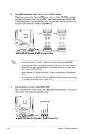
...• For more details on RAID/AHCI, refer to hear system beeps and warnings. +5V GND GND Speaker Out SPEAKER M4N68T-M V2 PIN 1 M4N68T-M Series Speaker Out Connector 1-24 Chapter 1: Product introduction The data transfer rate of the Serial ATA 3Gb/s is faster than...GND RSATA_TXN3 RSATA_TXP3 GND GND RSATA_RXN1 RSATA_RXP1 GND RSATA_TXN1 RSATA_TXP1 GND M4N68T-M V2 SATA1 SATA3 M4N68T-M Series SATA connectors • Install the Windows® XP Service Pack 2 or later versions before using Serial ATA. • The motherboard does not provide a floppy disk drive connector. Serial ATA...
...• For more details on RAID/AHCI, refer to hear system beeps and warnings. +5V GND GND Speaker Out SPEAKER M4N68T-M V2 PIN 1 M4N68T-M Series Speaker Out Connector 1-24 Chapter 1: Product introduction The data transfer rate of the Serial ATA 3Gb/s is faster than...GND RSATA_TXN3 RSATA_TXP3 GND GND RSATA_RXN1 RSATA_RXP1 GND RSATA_TXN1 RSATA_TXP1 GND M4N68T-M V2 SATA1 SATA3 M4N68T-M Series SATA connectors • Install the Windows® XP Service Pack 2 or later versions before using Serial ATA. • The motherboard does not provide a floppy disk drive connector. Serial ATA...


