
User Manual
Page 11
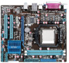
... with less power consumption. Before you for the following items. Motherboard Cables Accessories Application DVD Documentation ASUS M4N68T-M motherboard 2 x Serial ATA cables 1 x Ultra DMA 133/100 cable 1 x I/O shield ASUS motherboard Support DVD User Manual If any of ASUS quality motherboards! This motherboard also supports AMD® CPUs in the long line of the above...
... with less power consumption. Before you for the following items. Motherboard Cables Accessories Application DVD Documentation ASUS M4N68T-M motherboard 2 x Serial ATA cables 1 x Ultra DMA 133/100 cable 1 x I/O shield ASUS motherboard Support DVD User Manual If any of ASUS quality motherboards! This motherboard also supports AMD® CPUs in the long line of the above...

User Manual
Page 13
... support DVD or a USB flash disk that contains the BIOS file. ASUS CrashFree BIOS 3 ASUS CrashFree BIOS 3 is an ASUS exclusive OS that provides you with at least 1.2GB free disk space. ASUS M4N68T-M 1-3 ASUS MyLogo2™ Turn your system. 1.3.2 Innovative ASUS features ASUS Express Gate ASUS Express Gate is an auto-recovery tool that allows you to ensure...
... support DVD or a USB flash disk that contains the BIOS file. ASUS CrashFree BIOS 3 ASUS CrashFree BIOS 3 is an ASUS exclusive OS that provides you with at least 1.2GB free disk space. ASUS M4N68T-M 1-3 ASUS MyLogo2™ Turn your system. 1.3.2 Innovative ASUS features ASUS Express Gate ASUS Express Gate is an auto-recovery tool that allows you to ensure...

User Manual
Page 15
... due to static electricity. • Hold components by the edges to the motherboard, peripherals, or components. 1.4 Before you proceed Take note of the onboard LED. M4N68T-M SB_PWR ON OFF Standby Power Powered Off M4N68T-M Onboard LED ASUS M4N68T-M 1-5
... due to static electricity. • Hold components by the edges to the motherboard, peripherals, or components. 1.4 Before you proceed Take note of the onboard LED. M4N68T-M SB_PWR ON OFF Standby Power Powered Off M4N68T-M Onboard LED ASUS M4N68T-M 1-5

User Manual
Page 17
... PRI_IDE SOCKET AM3 VGA LPT 7 USBPW1-4 USB34 24.4cm(9.6in) LAN1_USB12 Super I/O CPU_FAN EATXPWR AUDIO CHA_FAN Lithium Cell CMOS Power M4N68T-M PCIEX16 3 8Mb BIOS RTL 8211CL PCIEX1_1 PCI1 NVIDIA® MCP68 SE 8 CLRTC 2 SATA2 SATA4 PCI2 VIA VT1708S SB_PWR F_PANEL ... 1-22 11. Digital audio connector (4-1 pin SPDIF_OUT) 1-27 7. IDE connector (40-1 pin PRI_IDE) 1-23 15. Clear RTC RAM (CLRTC) 1-18 ASUS M4N68T-M 1-7 System panel connector (10-1 pin F_PANEL) 1-25 5. DDR3 DIMM sockets 1-11 14. Keyboard power (3-pin KBPWR) 1-19 9. Front panel audio ...
... PRI_IDE SOCKET AM3 VGA LPT 7 USBPW1-4 USB34 24.4cm(9.6in) LAN1_USB12 Super I/O CPU_FAN EATXPWR AUDIO CHA_FAN Lithium Cell CMOS Power M4N68T-M PCIEX16 3 8Mb BIOS RTL 8211CL PCIEX1_1 PCI1 NVIDIA® MCP68 SE 8 CLRTC 2 SATA2 SATA4 PCI2 VIA VT1708S SB_PWR F_PANEL ... 1-22 11. Digital audio connector (4-1 pin SPDIF_OUT) 1-27 7. IDE connector (40-1 pin PRI_IDE) 1-23 15. Clear RTC RAM (CLRTC) 1-18 ASUS M4N68T-M 1-7 System panel connector (10-1 pin F_PANEL) 1-25 5. DDR3 DIMM sockets 1-11 14. Keyboard power (3-pin KBPWR) 1-19 9. Front panel audio ...

User Manual
Page 19
... fan connector DO NOT forget to the CPU_FAN connector on the side tab to plug this connector. The lever clicks on the motherboard. ASUS M4N68T-M 1-9 Install a CPU heatsink and fan following the instructions that it is in place, push down the socket lever to section 1.6.2 Installing heatsink and fan for ...
... fan connector DO NOT forget to the CPU_FAN connector on the side tab to plug this connector. The lever clicks on the motherboard. ASUS M4N68T-M 1-9 Install a CPU heatsink and fan following the instructions that it is in place, push down the socket lever to section 1.6.2 Installing heatsink and fan for ...

User Manual
Page 21
.... Ensure that the retention bracket is in place. 3. Align the other end of the DDR3 DIMM sockets: DIMM_A1 DIMM_B1 M4N68T-M Channel Channel A Channel B M4N68T-M 240-pin DDR3 DIMM sockets Sockets DIMM_A1 DIMM_B1 ASUS M4N68T-M 1-11 DO NOT forget to the module base. 5. Hardware monitoring errors can occur if you cannot snap the retention bracket...
.... Ensure that the retention bracket is in place. 3. Align the other end of the DDR3 DIMM sockets: DIMM_A1 DIMM_B1 M4N68T-M Channel Channel A Channel B M4N68T-M 240-pin DDR3 DIMM sockets Sockets DIMM_A1 DIMM_B1 ASUS M4N68T-M 1-11 DO NOT forget to the module base. 5. Hardware monitoring errors can occur if you cannot snap the retention bracket...

User Manual
Page 25
ASUS M4N68T-M 1-15 Size SS/ DS Brand Chip NO. Visit the ASUS website at www.asus.com for the latest QVL. Crucial CT12864BA1067.8FF 1024MB SS Crucial CT12872BA1067.9FF 1024MB SS Crucial CT25664BA1067.16FF 2048MB DS Crucial CT25672BA1067.18FF 2048MB DS ...
ASUS M4N68T-M 1-15 Size SS/ DS Brand Chip NO. Visit the ASUS website at www.asus.com for the latest QVL. Crucial CT12864BA1067.8FF 1024MB SS Crucial CT12872BA1067.9FF 1024MB SS Crucial CT25664BA1067.16FF 2048MB DS Crucial CT25672BA1067.18FF 2048MB DS ...

User Manual
Page 27
... slot that you intend to install expansion cards. Keep the screw for the card. 2. Turn on BIOS setup. 2. When using PCI cards on the slot. 5. ASUS M4N68T-M 1-17 Otherwise, conflicts will arise between the two PCI groups, making the system unstable and the card inoperable. 1.8.3 PCI slots The PCI slots support cards...
... slot that you intend to install expansion cards. Keep the screw for the card. 2. Turn on BIOS setup. 2. When using PCI cards on the slot. 5. ASUS M4N68T-M 1-17 Otherwise, conflicts will arise between the two PCI groups, making the system unstable and the card inoperable. 1.8.3 PCI slots The PCI slots support cards...

User Manual
Page 29
... wake up the computer from S1 sleep mode (CPU stopped, DRAM refreshed, system running in reduced power mode). KBPWR 12 23 +5V +5VSB (Default) M4N68T-M M4N68T-M Keyboard Power Setting ASUS M4N68T-M 1-19 USB device wake-up (3-pin USBPW1-4, USBPW5-10) Set these jumpers to +5VSB to wake up the computer by pressing a key on...
... wake up the computer from S1 sleep mode (CPU stopped, DRAM refreshed, system running in reduced power mode). KBPWR 12 23 +5V +5VSB (Default) M4N68T-M M4N68T-M Keyboard Power Setting ASUS M4N68T-M 1-19 USB device wake-up (3-pin USBPW1-4, USBPW5-10) Set these jumpers to +5VSB to wake up the computer by pressing a key on...

User Manual
Page 31
... SENSE2_RETUR AGND NC NC NC AAFP PIN 1 PIN 1 MIC2 MICPWR Line out_R NC Line out_L PORT1 L PORT1 R PORT2 R SENSE_SEND PORT2 L M4N68T-M HD-audio-compliant Legacy AC'97 pin definition compliant definition M4N68T-M Analog front panel connector • We recommend that supports either High Definition Audio or AC`97 audio standard. This 15... Serial Bus (USB) ports connect to USB 2.0 devices. 9. Video Graphics Adapter (VGA) port. See section 2.4.3 Chipset for pointing devices or other VGA-compatible devices. 10. ASUS M4N68T-M 1-21
... SENSE2_RETUR AGND NC NC NC AAFP PIN 1 PIN 1 MIC2 MICPWR Line out_R NC Line out_L PORT1 L PORT1 R PORT2 R SENSE_SEND PORT2 L M4N68T-M HD-audio-compliant Legacy AC'97 pin definition compliant definition M4N68T-M Analog front panel connector • We recommend that supports either High Definition Audio or AC`97 audio standard. This 15... Serial Bus (USB) ports connect to USB 2.0 devices. 9. Video Graphics Adapter (VGA) port. See section 2.4.3 Chipset for pointing devices or other VGA-compatible devices. 10. ASUS M4N68T-M 1-21

User Manual
Page 33
... configure your devices: Single device Two devices Drive jumper setting Cable-Select or Master Cable-Select Master Slave Mode of device(s) - PRI_IDE M4N68T-M PIN1 NOTE:Orient the red markings on the Ultra DMA cable connector. This prevents incorrect insertion when you connect the IDE cable. &#...the following modes to PIN 1. 3. There are three connectors on each Ultra DMA 133/100 signal cable: blue, black, and gray. M4N68T-M IDE connector ASUS M4N68T-M 1-23 IDE connector (40-1 pin PRI_IDE) The onboard IDE connector is set as "Cable-Select", ensure that all other device jumpers ...
... configure your devices: Single device Two devices Drive jumper setting Cable-Select or Master Cable-Select Master Slave Mode of device(s) - PRI_IDE M4N68T-M PIN1 NOTE:Orient the red markings on the Ultra DMA cable connector. This prevents incorrect insertion when you connect the IDE cable. &#...the following modes to PIN 1. 3. There are three connectors on each Ultra DMA 133/100 signal cable: blue, black, and gray. M4N68T-M IDE connector ASUS M4N68T-M 1-23 IDE connector (40-1 pin PRI_IDE) The onboard IDE connector is set as "Cable-Select", ensure that all other device jumpers ...

User Manual
Page 35
...-1 pin F_PANEL) This connector supports several chassis-mounted functions. Connect the chassis power LED cable to the HDD. • Power/Soft-off the system power. ASUS M4N68T-M 1-25 The system power LED lights up or flashes when data is read from or written to this connector. Ground Reset...
...-1 pin F_PANEL) This connector supports several chassis-mounted functions. Connect the chassis power LED cable to the HDD. • Power/Soft-off the system power. ASUS M4N68T-M 1-25 The system power LED lights up or flashes when data is read from or written to this connector. Ground Reset...

User Manual
Page 37
CPU_FAN CPU FAN PWM CPU FAN IN CPU FAN PWR GND M4N68T-M CHA_FAN Rotation +12V GND M4N68T-M fan connectors DO NOT forget to connect the fan cables to configure the setting. These are not jumpers! Digital audio connector (4-1 pin SPDIF_OUT) This ... audio connector Ensure that the black wire of each cable matches the ground pin of Sound playback is purchased separately. 9. ASUS M4N68T-M 1-27 Only the 4-pin CPU fan connector supports the ASUS Q-Fan feature. The S/PDIF module is VIA High Definition Audio (the name may damage the motherboard components. Insufficient air flow ...
CPU_FAN CPU FAN PWM CPU FAN IN CPU FAN PWR GND M4N68T-M CHA_FAN Rotation +12V GND M4N68T-M fan connectors DO NOT forget to connect the fan cables to configure the setting. These are not jumpers! Digital audio connector (4-1 pin SPDIF_OUT) This ... audio connector Ensure that the black wire of each cable matches the ground pin of Sound playback is purchased separately. 9. ASUS M4N68T-M 1-27 Only the 4-pin CPU fan connector supports the ASUS Q-Fan feature. The S/PDIF module is VIA High Definition Audio (the name may damage the motherboard components. Insufficient air flow ...

User Manual
Page 39
... you to manage, save, and update the motherboard BIOS in Windows® environment. • ASUS Update requires an Internet connection either of the following methods: Updating from the Internet, then click Next...ASUS Update To install ASUS Update: 1. Follow the onscreen instructions to avail all Windows® applications before you to avoid network traffic, or click Auto Select then click Next. From the Windows® desktop, click Start > Programs > ASUS > ASUS Update > ASUS Update to launch the ASUS Update utility. 2. Click the Utilities tab, then click ASUS Update. 3. ASUS M4N68T...
... you to manage, save, and update the motherboard BIOS in Windows® environment. • ASUS Update requires an Internet connection either of the following methods: Updating from the Internet, then click Next...ASUS Update To install ASUS Update: 1. Follow the onscreen instructions to avail all Windows® applications before you to avoid network traffic, or click Auto Select then click Next. From the Windows® desktop, click Start > Programs > ASUS > ASUS Update > ASUS Update to launch the ASUS Update utility. 2. Click the Utilities tab, then click ASUS Update. 3. ASUS M4N68T...

User Manual
Page 41
.... 3. Turn off the system after the utility completes the updating process and turn it and starts flashing the corrupted BIOS file. 4. ASUS M4N68T-M 2-3 2.1.3 ASUS CrashFree BIOS utility The ASUS CrashFree BIOS is found, the utility reads it on the system. 2. You can cause system boot failure! Download the latest BIOS file... from the ASUS website at www.asus.com. • The removable devices that contains the BIOS file to the USB port or to restore the BIOS file when it...
.... 3. Turn off the system after the utility completes the updating process and turn it and starts flashing the corrupted BIOS file. 4. ASUS M4N68T-M 2-3 2.1.3 ASUS CrashFree BIOS utility The ASUS CrashFree BIOS is found, the utility reads it on the system. 2. You can cause system boot failure! Download the latest BIOS file... from the ASUS website at www.asus.com. • The removable devices that contains the BIOS file to the USB port or to restore the BIOS file when it...

User Manual
Page 43
... General help Use [ENTER], [TAB] or [SHIFT-TAB] to select items in the menu and change the settings. Use the navigation keys to select a field. ASUS M4N68T-M 2-5 To select an item on the menu bar, press the right or left arrow key on top of the navigation keys differ from one screen...
... General help Use [ENTER], [TAB] or [SHIFT-TAB] to select items in the menu and change the settings. Use the navigation keys to select a field. ASUS M4N68T-M 2-5 To select an item on the menu bar, press the right or left arrow key on top of the navigation keys differ from one screen...

User Manual
Page 45
... screen appears, giving you to configure system Time. Select Screen Select Item +- Select an item then press to navigate through them. Configuration options: [Disabled] [Enabled] ASUS M4N68T-M 2-7 Refer to section 2.2.1 BIOS menu screen for information on the menu screen items and how to display the submenu. Use [+] or [-] to configure your storage...
... screen appears, giving you to configure system Time. Select Screen Select Item +- Select an item then press to navigate through them. Configuration options: [Disabled] [Enabled] ASUS M4N68T-M 2-7 Refer to section 2.2.1 BIOS menu screen for information on the menu screen items and how to display the submenu. Use [+] or [-] to configure your storage...

User Manual
Page 47
Processor Displays the auto-detected CPU specification. Configuration options: [Manual] [Auto] [Standard] [Overclock Profile] ASUS M4N68T-M 2-9 Change Field Tab Select Field F1 General Help F10 Save and Exit ESC Exit v02.61 (C)Copyright 1985-2009, American Megatrends, Inc. 2.4.1 JumperFree Configuration The ...
Processor Displays the auto-detected CPU specification. Configuration options: [Manual] [Auto] [Standard] [Overclock Profile] ASUS M4N68T-M 2-9 Change Field Tab Select Field F1 General Help F10 Save and Exit ESC Exit v02.61 (C)Copyright 1985-2009, American Megatrends, Inc. 2.4.1 JumperFree Configuration The ...

User Manual
Page 49
...] for safe mode. VDDNB Over Voltage [Auto] Sets the VDDNB over voltage. Use / keys to adjust the ratio. Configuration options: [Auto] [Max. = 1.60000V] [Min. = 1.20000V] ASUS M4N68T-M 2-11
...] for safe mode. VDDNB Over Voltage [Auto] Sets the VDDNB over voltage. Use / keys to adjust the ratio. Configuration options: [Auto] [Max. = 1.60000V] [Min. = 1.20000V] ASUS M4N68T-M 2-11

User Manual
Page 51
... options: [Enabled] [Disabled] OnBoard LAN Boot ROM [Disabled] This item appears only when the MAC LAN item is set to [Auto]. Configuration options: [Disabled] [Enabled] ASUS M4N68T-M 2-13 Configuration options: [Auto] [32MB] [64MB] [128MB] [256MB] Azalia Audio [Auto] Enables or disables the Azalia audio controller. Configuration options: [PCIE -> PCI -> IGP] [IGD -> PCI...
... options: [Enabled] [Disabled] OnBoard LAN Boot ROM [Disabled] This item appears only when the MAC LAN item is set to [Auto]. Configuration options: [Disabled] [Enabled] ASUS M4N68T-M 2-13 Configuration options: [Auto] [32MB] [64MB] [128MB] [256MB] Azalia Audio [Auto] Enables or disables the Azalia audio controller. Configuration options: [PCIE -> PCI -> IGP] [IGD -> PCI...


