
User Manual
Page 3
... Typography x KFSN4-DRE Series specifications summary xi Chapter 1: Product introduction 1.1 Welcome 1-1 1.2 Package contents 1-1 1.3 Serial number label 1-1 1.4 Special features 1-2 1.4.1 Product highlights 1-2 1.4.2 Innovative ASUS features 1-3 Chapter 2: Hardware information 2.1 Before you proceed 2-1 2.2 Motherboard overview 2-3 2.2.1 Placement direction 2-3 2.2.2 Screw holes 2-3 2.2.4 Motherboard layouts 2-4 2.2.5 Layout contents 2-7 2.3 Central Processing Unit (CPU 2-9 2.3.1 Installing the CPU 2-9 2.3.2 Installing the heatsink 2-12 2.4 System memory 2-13 2.4.1 Overview...
... Typography x KFSN4-DRE Series specifications summary xi Chapter 1: Product introduction 1.1 Welcome 1-1 1.2 Package contents 1-1 1.3 Serial number label 1-1 1.4 Special features 1-2 1.4.1 Product highlights 1-2 1.4.2 Innovative ASUS features 1-3 Chapter 2: Hardware information 2.1 Before you proceed 2-1 2.2 Motherboard overview 2-3 2.2.1 Placement direction 2-3 2.2.2 Screw holes 2-3 2.2.4 Motherboard layouts 2-4 2.2.5 Layout contents 2-7 2.3 Central Processing Unit (CPU 2-9 2.3.1 Installing the CPU 2-9 2.3.2 Installing the heatsink 2-12 2.4 System memory 2-13 2.4.1 Overview...

User Manual
Page 16
...motherboard comes with the new socket supports registered DDR2-667/533 memory, delivering advanced performance and ensuring reliable data protection. HyperTransport™ Technology HyperTransport™ Technology is the latest storage interface for enterprise-class storage devices. Serial Attached SCSI (SAS) technology support (KFSN4-DRE... new industry standard that speeds up to meet demands for AMD Opteron™ 2000 series processors. DDR2 memory support The motherboard supports DDR2 memory which features data transfer rates of 667 MHz or 533 MHz to 10.7 GB/s. This high speed ...
...motherboard comes with the new socket supports registered DDR2-667/533 memory, delivering advanced performance and ensuring reliable data protection. HyperTransport™ Technology HyperTransport™ Technology is the latest storage interface for enterprise-class storage devices. Serial Attached SCSI (SAS) technology support (KFSN4-DRE... new industry standard that speeds up to meet demands for AMD Opteron™ 2000 series processors. DDR2 memory support The motherboard supports DDR2 memory which features data transfer rates of 667 MHz or 533 MHz to 10.7 GB/s. This high speed ...

User Manual
Page 20
Chapter summary 2 2.1 Before you proceed 2-1 2.2 Motherboard overview 2-3 2.3 Central Processing Unit (CPU 2-9 2.4 System memory 2-13 2.5 Expansion slots 2-16 2.6 Jumpers 2-19 2.7 Connectors 2-23 ASUS KFSN4-DRE Series
Chapter summary 2 2.1 Before you proceed 2-1 2.2 Motherboard overview 2-3 2.3 Central Processing Unit (CPU 2-9 2.4 System memory 2-13 2.5 Expansion slots 2-16 2.6 Jumpers 2-19 2.7 Connectors 2-23 ASUS KFSN4-DRE Series

User Manual
Page 22
... (MEM_WARN1) The memory warning LED lights up to indicate that the LSI 1064E chipset is working normally. ® KFSN4-DRE Series SAS LED LED1 Blinks Normal (green) OFF Abnormal 3. CPU warning LED (CPU_WARN1) The CPU warning LED lights up to indicate that a ... or the processor is no power in CPU 1 socket. 4. 2. SAS LED (for KFSN4-DRE/SAS only) The green heartbeat LED blinks per second to indicate that there is not installed properly in the memory DIMMs. ® KFSN4-DRE Series Onboard LED MEM_WARN1 (green) ON Abnormal OFF Normal CPU_WARN1 (green) ON Abnormal OFF ...
... (MEM_WARN1) The memory warning LED lights up to indicate that the LSI 1064E chipset is working normally. ® KFSN4-DRE Series SAS LED LED1 Blinks Normal (green) OFF Abnormal 3. CPU warning LED (CPU_WARN1) The CPU warning LED lights up to indicate that a ... or the processor is no power in CPU 1 socket. 4. 2. SAS LED (for KFSN4-DRE/SAS only) The green heartbeat LED blinks per second to indicate that there is not installed properly in the memory DIMMs. ® KFSN4-DRE Series Onboard LED MEM_WARN1 (green) ON Abnormal OFF Normal CPU_WARN1 (green) ON Abnormal OFF ...

User Manual
Page 33
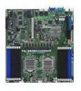
... memory 2.4.1 Overview The motherboard comes with sixteen (16) Double Data Rate 2 (DDR2) Dual Inline Memory Modules (DIMM) sockets. The figure illustrates the location of the DDR2 DIMM sockets: ® KFSN4-DRE Series... 240-pin DIMM sockets 128 Pins 112 Pins DIMM_B4 DIMM_A4 DIMM_B3 DIMM_A3 DIMM_B2 DIMM_A2 DIMM_B1 DIMM_A1 DIMM_C1 DIMM_D1 DIMM_C2 DIMM_D2 DIMM_C3 DIMM_D3 DIMM_C4 DIMM_D4 ASUS KFSN4-DRE...
... memory 2.4.1 Overview The motherboard comes with sixteen (16) Double Data Rate 2 (DDR2) Dual Inline Memory Modules (DIMM) sockets. The figure illustrates the location of the DDR2 DIMM sockets: ® KFSN4-DRE Series... 240-pin DIMM sockets 128 Pins 112 Pins DIMM_B4 DIMM_A4 DIMM_B3 DIMM_A3 DIMM_B2 DIMM_A2 DIMM_B1 DIMM_A1 DIMM_C1 DIMM_D1 DIMM_C2 DIMM_D2 DIMM_C3 DIMM_D3 DIMM_C4 DIMM_D4 ASUS KFSN4-DRE...

User Manual
Page 34
..., 1 GB, 2, or 4 GB registered ECC DDR2 DIMMs into the DIMM sockets using the memory configurations in this section. • For dual-channel configuration, the total size of memory module(s) installed per channel must be the same for better performance. Memory population table CPU1 SingleChannel Dual Channel CPU2 Single Channel Dual Channel A1 B1...=DIMM_A2=DIMM_B1=DIMM_B2= DIMM_C1=DIMM_C2 =DIMM_D1=DIMM_D2 • Always install DIMMs with the same CAS latency. For optimum compatibility, it is recommended that you obtain memory modules from the same vendor.
..., 1 GB, 2, or 4 GB registered ECC DDR2 DIMMs into the DIMM sockets using the memory configurations in this section. • For dual-channel configuration, the total size of memory module(s) installed per channel must be the same for better performance. Memory population table CPU1 SingleChannel Dual Channel CPU2 Single Channel Dual Channel A1 B1...=DIMM_A2=DIMM_B1=DIMM_B2= DIMM_C1=DIMM_C2 =DIMM_D1=DIMM_D2 • Always install DIMMs with the same CAS latency. For optimum compatibility, it is recommended that you obtain memory modules from the same vendor.

User Manual
Page 39
... as system passwords. 2.6 Jumpers 1. To erase the RTC RAM: 1. Removing the cap will cause system boot failure! ® CLRTC1 2 1 Normal (Default) 3 2 Clear CMOS KFSN4-DRE Series Clear RTC RAM ASUS KFSN4-DRE Series 2-19 Move the jumper cap from pins 1-2 (default) to re-enter data. Plug the power cord and turn ON the computer. 6. Clear... 1-2. 4. Reinstall the battery. 5. Turn OFF the computer and unplug the power cord. 2. Keep the cap on CLRTC jumper default position. You can clear the CMOS memory of date, time, and system setup parameters by erasing the CMOS RTC RAM data.
... as system passwords. 2.6 Jumpers 1. To erase the RTC RAM: 1. Removing the cap will cause system boot failure! ® CLRTC1 2 1 Normal (Default) 3 2 Clear CMOS KFSN4-DRE Series Clear RTC RAM ASUS KFSN4-DRE Series 2-19 Move the jumper cap from pins 1-2 (default) to re-enter data. Plug the power cord and turn ON the computer. 6. Clear... 1-2. 4. Reinstall the battery. 5. Turn OFF the computer and unplug the power cord. 2. Keep the cap on CLRTC jumper default position. You can clear the CMOS memory of date, time, and system setup parameters by erasing the CMOS RTC RAM data.

User Manual
Page 69
... Version 1000.005 Date 07/10/2007 AGESA Version: 03.00.09 Processor Information System Memory Information BIOS SETUP UTILITY →← Select Screen ↑↓ Select Item +- ASUS KFSN4-DRE Series 4-11 PIO Mode [Auto] Allows you an overview of the general system specifications.... Data Transfer [Disabled] Enables or disables 32-bit data transfer. Change Field Tab Select Field F1 General Help F10 Save and Exit ESC Exit V02.61 (C)Copyright 1985-2006, American Megatrends, Inc. Configuration options: [Auto] [SWDMA0] [SWDMA1] [SWDMA2] [MWDMA0] [MWDMA1] [MWDMA2] [UDMA0] [UDMA1] ...
... Version 1000.005 Date 07/10/2007 AGESA Version: 03.00.09 Processor Information System Memory Information BIOS SETUP UTILITY →← Select Screen ↑↓ Select Item +- ASUS KFSN4-DRE Series 4-11 PIO Mode [Auto] Allows you an overview of the general system specifications.... Data Transfer [Disabled] Enables or disables 32-bit data transfer. Change Field Tab Select Field F1 General Help F10 Save and Exit ESC Exit V02.61 (C)Copyright 1985-2006, American Megatrends, Inc. Configuration options: [Auto] [SWDMA0] [SWDMA1] [SWDMA2] [MWDMA0] [MWDMA1] [MWDMA2] [UDMA0] [UDMA1] ...

User Manual
Page 70
... Tab Select Field F1 General Help F10 Save and Exit ESC Exit V02.61 (C)Copyright 1985-2006, American Megatrends, Inc. 4-12 Chapter 4: BIOS setup None DIMM_A4 - Main System Memory Information BIOS SETUP UTILITY Total Memory 2048MB Node1 Memory Configuration Node2 Memory Configuration Node1/2 Memory Configuration Main Speed DDR2 400 DIMM_A1 - Change Field Tab Select Field F1...
... Tab Select Field F1 General Help F10 Save and Exit ESC Exit V02.61 (C)Copyright 1985-2006, American Megatrends, Inc. 4-12 Chapter 4: BIOS setup None DIMM_A4 - Main System Memory Information BIOS SETUP UTILITY Total Memory 2048MB Node1 Memory Configuration Node2 Memory Configuration Node1/2 Memory Configuration Main Speed DDR2 400 DIMM_A1 - Change Field Tab Select Field F1...

User Manual
Page 72
... The Chipset configuration menu allows you to change advanced chipset settings. Advanced BIOS SETUP UTILITY NorthBridge Configuration Memory Configuration DRAM Timing Configuration ECC Configuration IOMMU Option Menu Memory CLK :200 MHz CAS Latency(Tcl) :3.0 RAS/CAS Delay(Trcd) :3 CLK Row Precharge Time...: [Continuous] [Discrete] PowerNow [Enabled] Enables or disables the generation of system memory. Change Field Tab Select Field F1 General Help F10 Save and Exit ESC Exit V02.61 (C)Copyright 1985-2006, American Megatrends, Inc. Change Field Tab Select Field F1 General...
... The Chipset configuration menu allows you to change advanced chipset settings. Advanced BIOS SETUP UTILITY NorthBridge Configuration Memory Configuration DRAM Timing Configuration ECC Configuration IOMMU Option Menu Memory CLK :200 MHz CAS Latency(Tcl) :3.0 RAS/CAS Delay(Trcd) :3 CLK Row Precharge Time...: [Continuous] [Discrete] PowerNow [Enabled] Enables or disables the generation of system memory. Change Field Tab Select Field F1 General Help F10 Save and Exit ESC Exit V02.61 (C)Copyright 1985-2006, American Megatrends, Inc. Change Field Tab Select Field F1 General...

User Manual
Page 73
... Item +- Change Field Tab Select Field F1 General Help F10 Save and Exit ESC Exit V02.61 (C)Copyright 1985-2006, American Megatrends, Inc. Configuration options: [Disabled] [Auto] [Reserved] [Reserved] [Reserved] Node Interleaving [Disabled] Enables node interleaving. Configuration options: [Disabled] [Enabled] ASUS KFSN4-DRE Series 4-15 Memory Configuration The memory configuration menu allows you to change the...
... Item +- Change Field Tab Select Field F1 General Help F10 Save and Exit ESC Exit V02.61 (C)Copyright 1985-2006, American Megatrends, Inc. Configuration options: [Disabled] [Auto] [Reserved] [Reserved] [Reserved] Node Interleaving [Disabled] Enables node interleaving. Configuration options: [Disabled] [Enabled] ASUS KFSN4-DRE Series 4-15 Memory Configuration The memory configuration menu allows you to change the...

User Manual
Page 74
...] [4 CLK] [5 CLK] [6 CLK] [Auto] 4-16 Chapter 4: BIOS setup DRAM Timing Configuration Main Advanced BIOS SETUP UTILITY DRAM Timing Configuration Memory Clock Mode DRAM Timing Mode [Auto] [Auto] Options Auto Limit Manual Memory Clock Mode [Auto] Configuration options: [Auto] [Limit] [Manual] The following items appear when DRAM Timing Mode is set to [DCT... [400 MHz] [533 MHz] DRAM Timing Mode [Auto] Allows you to [Limit] or [Manual]. Configuration options: [Auto] [DCT 0] [DCT 1] [Both] The following item appears when Memory Clock Mode is set to select the DRAM timing mode.
...] [4 CLK] [5 CLK] [6 CLK] [Auto] 4-16 Chapter 4: BIOS setup DRAM Timing Configuration Main Advanced BIOS SETUP UTILITY DRAM Timing Configuration Memory Clock Mode DRAM Timing Mode [Auto] [Auto] Options Auto Limit Manual Memory Clock Mode [Auto] Configuration options: [Auto] [Limit] [Manual] The following items appear when DRAM Timing Mode is set to [DCT... [400 MHz] [533 MHz] DRAM Timing Mode [Auto] Allows you to [Limit] or [Manual]. Configuration options: [Auto] [DCT 0] [DCT 1] [Both] The following item appears when Memory Clock Mode is set to select the DRAM timing mode.

User Manual
Page 78
... Plug and Play devices not required for legacy ISA devices. Change Field Tab Select Field F1 General Help F10 Save and Exit ESC Exit V02.61 (C)Copyright 1985-2006, American Megatrends, Inc. Reset ESCD Data [No] Clears the non-volatile RAM (NVRAM) during System Boot. →← ...[Enabled] Allows you to malfunction. The menu includes setting IRQ and DMA channel resources for either PCI/PnP or legacy ISA devices, and setting the memory size block for boot. Configuration options: [No] [Yes] Palette Snooping [Disabled] When set to [No], BIOS configures all the devices in the...
... Plug and Play devices not required for legacy ISA devices. Change Field Tab Select Field F1 General Help F10 Save and Exit ESC Exit V02.61 (C)Copyright 1985-2006, American Megatrends, Inc. Reset ESCD Data [No] Clears the non-volatile RAM (NVRAM) during System Boot. →← ...[Enabled] Allows you to malfunction. The menu includes setting IRQ and DMA channel resources for either PCI/PnP or legacy ISA devices, and setting the memory size block for boot. Configuration options: [No] [Yes] Palette Snooping [Disabled] When set to [No], BIOS configures all the devices in the...


