
User Manual
Page 4
... time 3-1 3.2 Powering off the computer 3-2 3.2.1 Using the OS shut down function 3-2 3.2.2 Using the dual function power switch 3-2 Chapter 4: BIOS setup 4.1 Managing and updating your BIOS 4-1 4.1.1 Creating a bootable floppy disk 4-1 4.1.2 AFUDOS utility 4-2 4.1.3 ASUS CrashFree BIOS 2 utility 4-4 4.2 BIOS setup program 4-5 4.2.1 BIOS menu screen 4-6 4.2.2 Menu bar 4-6 4.2.3 Navigation keys 4-6 4.2.4 Menu items 4-7 4.2.5 Sub-menu items 4-7 4.2.6 Configuration fields 4-7 4.2.7 Pop-up window 4-7 4.2.8 Scroll...
... time 3-1 3.2 Powering off the computer 3-2 3.2.1 Using the OS shut down function 3-2 3.2.2 Using the dual function power switch 3-2 Chapter 4: BIOS setup 4.1 Managing and updating your BIOS 4-1 4.1.1 Creating a bootable floppy disk 4-1 4.1.2 AFUDOS utility 4-2 4.1.3 ASUS CrashFree BIOS 2 utility 4-4 4.2 BIOS setup program 4-5 4.2.1 BIOS menu screen 4-6 4.2.2 Menu bar 4-6 4.2.3 Navigation keys 4-6 4.2.4 Menu items 4-7 4.2.5 Sub-menu items 4-7 4.2.6 Configuration fields 4-7 4.2.7 Pop-up window 4-7 4.2.8 Scroll...

User Manual
Page 5
... 5-1 5.1.1 RAID definitions 5-1 5.1.2 Installing hard disk drives 5-2 5.1.3 Setting the BIOS RAID items 5-2 5.1.4 RAID configuration utilities 5-2 5.2 NVIDIA® RAID configurations 5-3 5.2.1 Entering the NVIDIA® RAID Utility 5-3 5.2.2 Creating a RAID Volume 5-4 5.2.3 Rebuilding a RAID set 5-6 5.2.4 Deleting a RAID array 5-7 5.2.5 Clearing the disk data 5-8 5.3 LSI Logic MPT Setup Utility (KFSN4-DRE/SAS model only 5-9 5.3.1 Integrated Mirroring 5-9 5.3.2 Integrated Mirroring Enhanced 5-13...
... 5-1 5.1.1 RAID definitions 5-1 5.1.2 Installing hard disk drives 5-2 5.1.3 Setting the BIOS RAID items 5-2 5.1.4 RAID configuration utilities 5-2 5.2 NVIDIA® RAID configurations 5-3 5.2.1 Entering the NVIDIA® RAID Utility 5-3 5.2.2 Creating a RAID Volume 5-4 5.2.3 Rebuilding a RAID set 5-6 5.2.4 Deleting a RAID array 5-7 5.2.5 Clearing the disk data 5-8 5.3 LSI Logic MPT Setup Utility (KFSN4-DRE/SAS model only 5-9 5.3.1 Integrated Mirroring 5-9 5.3.2 Integrated Mirroring Enhanced 5-13...

User Manual
Page 9
...: • Chapter 1: Product introduction This chapter describes the features of the BIOS parameters are not part of shutting down the system. • Chapter 4: BIOS setup This chapter tells how to when configuring the motherboard. ix ASUS websites The ASUS website provides updated information on the motherboard. • Chapter 3: Powering up This chapter describes the power up...
...: • Chapter 1: Product introduction This chapter describes the features of the BIOS parameters are not part of shutting down the system. • Chapter 4: BIOS setup This chapter tells how to when configuring the motherboard. ix ASUS websites The ASUS website provides updated information on the motherboard. • Chapter 3: Powering up This chapter describes the power up...

User Manual
Page 17
...cool, and efficient operation. USB 2.0 technology The motherboard implements the Universal Serial Bus (USB) 2.0 specification, dramatically increasing the connection speed from the support CD in case when the BIOS codes and data are corrupted. The system fan ...motherboard comes with dual Gigabit LAN controllers to provide comprehensive solution for critical components. 1.4.2 Innovative ASUS features CrashFree BIOS 2 This feature allows you to restore the original BIOS data from the 12 Mbps bandwidth on USB 1.1 to ensure stable supply of the current Serial ATA products. ASUS KFSN4-DRE...
...cool, and efficient operation. USB 2.0 technology The motherboard implements the Universal Serial Bus (USB) 2.0 specification, dramatically increasing the connection speed from the support CD in case when the BIOS codes and data are corrupted. The system fan ...motherboard comes with dual Gigabit LAN controllers to provide comprehensive solution for critical components. 1.4.2 Innovative ASUS features CrashFree BIOS 2 This feature allows you to restore the original BIOS data from the 12 Mbps bandwidth on USB 1.1 to ensure stable supply of the current Serial ATA products. ASUS KFSN4-DRE...

User Manual
Page 27
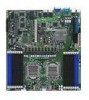
... 2-23 ASUS KFSN4-DRE Series 2-7 PCI Express x 16 slots 4. VGA Graphics controller setting (3-pin VGA_EN1) 4. PS/2 keyboard port (purple) 4. BMC socket Page 2-9 2-13 2-18 2-18 Jumpers 1. Gigabit LAN1 controller setting (3-pin LAN1_EN1, LAN2_EN1) 3. RJ-45 port for iKVM 3. USB 2.0 ports 1 and 2 5. DDR2 sockets 3. Clear RTC RAM (CLRTC1) 2. PS/2 mouse port (green) 2. Force BIOS recovery setting...
... 2-23 ASUS KFSN4-DRE Series 2-7 PCI Express x 16 slots 4. VGA Graphics controller setting (3-pin VGA_EN1) 4. PS/2 keyboard port (purple) 4. BMC socket Page 2-9 2-13 2-18 2-18 Jumpers 1. Gigabit LAN1 controller setting (3-pin LAN1_EN1, LAN2_EN1) 3. RJ-45 port for iKVM 3. USB 2.0 ports 1 and 2 5. DDR2 sockets 3. Clear RTC RAM (CLRTC1) 2. PS/2 mouse port (green) 2. Force BIOS recovery setting...

User Manual
Page 36
... installing the expansion card, read the documentation that the cards do so may need IRQ assignments. Remove the system unit cover (if your motherboard is completely seated on the slot. 5. Replace the system cover. 2.5.2 Configuring an expansion card After installing the expansion card, configure the ...it and make the necessary hardware settings for later use . When using PCI cards on BIOS setup. 2. Remove the bracket opposite the slot that they support. See Chapter 4 for the expansion card. Keep the screw for the ...
... installing the expansion card, read the documentation that the cards do so may need IRQ assignments. Remove the system unit cover (if your motherboard is completely seated on the slot. 5. Replace the system cover. 2.5.2 Configuring an expansion card After installing the expansion card, configure the ...it and make the necessary hardware settings for later use . When using PCI cards on BIOS setup. 2. Remove the bracket opposite the slot that they support. See Chapter 4 for the expansion card. Keep the screw for the ...

User Manual
Page 39
... you to pins 1-2. 4. Turn OFF the computer and unplug the power cord. 2. Hold down the key during the boot process and enter BIOS setup to pins 2-3. The onboard button cell battery powers the RAM data in CMOS. Except when clearing the RTC RAM, NEVER remove the cap... cap on CLRTC jumper default position. Removing the cap will cause system boot failure! ® CLRTC1 2 1 Normal (Default) 3 2 Clear CMOS KFSN4-DRE Series Clear RTC RAM ASUS KFSN4-DRE Series 2-19 2.6 Jumpers 1. To erase the RTC RAM: 1. Plug the power cord and turn ON the computer. 6. You can clear the CMOS...
... you to pins 1-2. 4. Turn OFF the computer and unplug the power cord. 2. Hold down the key during the boot process and enter BIOS setup to pins 2-3. The onboard button cell battery powers the RAM data in CMOS. Except when clearing the RTC RAM, NEVER remove the cap... cap on CLRTC jumper default position. Removing the cap will cause system boot failure! ® CLRTC1 2 1 Normal (Default) 3 2 Clear CMOS KFSN4-DRE Series Clear RTC RAM ASUS KFSN4-DRE Series 2-19 2.6 Jumpers 1. To erase the RTC RAM: 1. Plug the power cord and turn ON the computer. 6. You can clear the CMOS...

User Manual
Page 42
... system to quickly update or recover the BIOS settings when it becomes corrupted. Insert the floppy disk then turn on the system. ® RECOVERY1 12 23 Disable (Default) KFSN4-DRE Series BIOS recovery setting Enable 2-22 Chapter 2: Hardware information 6. Prepare a floppy disk that contains the latest BIOS for your motherboard model. 2. Set the jumper to pins...
... system to quickly update or recover the BIOS settings when it becomes corrupted. Insert the floppy disk then turn on the system. ® RECOVERY1 12 23 Disable (Default) KFSN4-DRE Series BIOS recovery setting Enable 2-22 Chapter 2: Hardware information 6. Prepare a floppy disk that contains the latest BIOS for your motherboard model. 2. Set the jumper to pins...

User Manual
Page 52
...warning speaker (Orange 4-pin SPKROUT) This 4-pin connector is for the chassis-mounted reset button for easy connection. The speaker allows you turn on the BIOS settings. Connect the chassis power LED cable to hear system beeps and warnings. • Power/Soft-off the system power. 2-32 Chapter 2: Hardware ... connector supports several chassis-mounted functions. POWERLED+ NC POWERLEDMLED+ MLEDNC +5V GND GND SPKROUT ® IDELED+ IDELEDNMIBTN# GND POWERBTN# GND NC RESETBTN# GND PANEL1 KFSN4-DRE Series System panel connector The system panel connector is for the system power button.
...warning speaker (Orange 4-pin SPKROUT) This 4-pin connector is for the chassis-mounted reset button for easy connection. The speaker allows you turn on the BIOS settings. Connect the chassis power LED cable to hear system beeps and warnings. • Power/Soft-off the system power. 2-32 Chapter 2: Hardware ... connector supports several chassis-mounted functions. POWERLED+ NC POWERLEDMLED+ MLEDNC +5V GND GND SPKROUT ® IDELED+ IDELEDNMIBTN# GND POWERBTN# GND NC RESETBTN# GND PANEL1 KFSN4-DRE Series System panel connector The system panel connector is for the system power button.

User Manual
Page 55
Connect the power cord to enter the BIOS Setup. External SCSI devices (starting with ATX power supplies, the system LED lights up for assistance. 7. ...-test or POST. Monitor b. If you do not see anything within 30 seconds from the time you press the ATX power button. ASUS KFSN4-DRE Series 3-1 Check the jumper settings and connections or call your monitor complies with a surge protector. 5. Connect the power cord to ... you turned on the power, the system may light up . After making all switches are running, the BIOS beeps or additional messages appear on the chain) c.
Connect the power cord to enter the BIOS Setup. External SCSI devices (starting with ATX power supplies, the system LED lights up for assistance. 7. ...-test or POST. Monitor b. If you do not see anything within 30 seconds from the time you press the ATX power button. ASUS KFSN4-DRE Series 3-1 Check the jumper settings and connections or call your monitor complies with a surge protector. 5. Connect the power cord to ... you turned on the power, the system may light up . After making all switches are running, the BIOS beeps or additional messages appear on the chain) c.

User Manual
Page 56
.... 6. If necessary, key in Chapter 4 for less than four seconds lets the system enter the soft-off mode regardless of the BIOS setting. 3.2 Powering off mode, depending on the BIOS setting. Pressing the power switch for more than four seconds puts the system to sleep mode or to section "4.5 Power Menu" in...
.... 6. If necessary, key in Chapter 4 for less than four seconds lets the system enter the soft-off mode regardless of the BIOS setting. 3.2 Powering off mode, depending on the BIOS setting. Pressing the power switch for more than four seconds puts the system to sleep mode or to section "4.5 Power Menu" in...

User Manual
Page 57
Detailed descriptions of the BIOS parameters are also provided. This chapter tells how to change the system settings through the BIOS Setup BIOS se4tup menus.
Detailed descriptions of the BIOS parameters are also provided. This chapter tells how to change the system settings through the BIOS Setup BIOS se4tup menus.

User Manual
Page 58
Chapter summary 4 4.1 Managing and updating your BIOS 4-1 4.2 BIOS setup program 4-5 4.3 Main menu 4-8 4.4 Advanced menu 4-13 4.5 Server menu 4-27 4.6 Security menu 4-29 4.7 Boot menu 4-31 4.8 Exit menu 4-33 ASUS KFSN4-DRE Series
Chapter summary 4 4.1 Managing and updating your BIOS 4-1 4.2 BIOS setup program 4-5 4.3 Main menu 4-8 4.4 Advanced menu 4-13 4.5 Server menu 4-27 4.6 Security menu 4-29 4.7 Boot menu 4-31 4.8 Exit menu 4-33 ASUS KFSN4-DRE Series

User Manual
Page 59
... disk 1. Copy the original motherboard BIOS using a bootable floppy disk) 2. At the DOS prompt, type format A:/S then press . Click File from the Windows® desktop, then select My Computer. Insert a formatted, high density 1.44 MB floppy disk into the drive. Press , then follow screen instructions to the optical drive. ASUS KFSN4-DRE Series 4-1 4.1 Managing and...
... disk 1. Copy the original motherboard BIOS using a bootable floppy disk) 2. At the DOS prompt, type format A:/S then press . Click File from the Windows® desktop, then select My Computer. Insert a formatted, high density 1.44 MB floppy disk into the drive. Press , then follow screen instructions to the optical drive. ASUS KFSN4-DRE Series 4-1 4.1 Managing and...

User Manual
Page 60
.... 1. The utility copies the current BIOS file to file...... Visit the ASUS website (www.asus.com) and download the latest BIOS file for the motherboard. done Write to the floppy disk. Reading flash ..... ok A:\> The utility returns to a bootable floppy disk. 4-2 Chapter 4: BIOS setup Updating the BIOS file To update the BIOS file using the AFUDOS utility: •...
.... 1. The utility copies the current BIOS file to file...... Visit the ASUS website (www.asus.com) and download the latest BIOS file for the motherboard. done Write to the floppy disk. Reading flash ..... ok A:\> The utility returns to a bootable floppy disk. 4-2 Chapter 4: BIOS setup Updating the BIOS file To update the BIOS file using the AFUDOS utility: •...

User Manual
Page 61
... from the hard disk drive. The utility verifies the file and starts updating the BIOS. Erasing flash ...... done Please restart your computer A:\> ASUS KFSN4-DRE Series 4-3 Do not turn off power during flash BIOS Reading file ....... Version 1.19(ASUS V2.07(03.11.24BB)) Copyright (C) 2002 American Megatrends, Inc. A:\>afudos /iKFSN4DRE... to the bootable floppy disk you created earlier. 3. All rights reserved. done Reading flash ...... Reboot the system from the motherboard support CD to the DOS prompt after the BIOS update process is the latest or the original...
... from the hard disk drive. The utility verifies the file and starts updating the BIOS. Erasing flash ...... done Please restart your computer A:\> ASUS KFSN4-DRE Series 4-3 Do not turn off power during flash BIOS Reading file ....... Version 1.19(ASUS V2.07(03.11.24BB)) Copyright (C) 2002 American Megatrends, Inc. A:\>afudos /iKFSN4DRE... to the bootable floppy disk you created earlier. 3. All rights reserved. done Reading flash ...... Reboot the system from the motherboard support CD to the DOS prompt after the BIOS update process is the latest or the original...

User Manual
Page 62
... the motherboard support CD or the floppy disk containing the updated motherboard BIOS before using this motherboard from a floppy disk: 1. You can cause system boot failure! 4. Floppy found , the utility reads the BIOS file and starts flashing the corrupted BIOS file. Recovering the BIOS from a floppy disk To recover the BIOS from ASUS website (support.asus.com/download). 3. Bad BIOS checksum...
... the motherboard support CD or the floppy disk containing the updated motherboard BIOS before using this motherboard from a floppy disk: 1. You can cause system boot failure! 4. Floppy found , the utility reads the BIOS file and starts flashing the corrupted BIOS file. Recovering the BIOS from a floppy disk To recover the BIOS from ASUS website (support.asus.com/download). 3. Bad BIOS checksum...

User Manual
Page 63
... chassis. ASUS KFSN4-DRE Series 4-5 The Setup program is designed to make your system using the provided utility described in this section are installing a motherboard, reconfiguring your screen. • Visit the ASUS website (www.asus.com) to "Run Setup." This section explains how to reconfigure your BIOS. For example... Being a menu-driven program, it as easy to enter the Setup utility; If you see on the motherboard stores the Setup utility. Use the BIOS Setup program when you are for reference purposes only, and may not exactly match what you wish to enter...
... chassis. ASUS KFSN4-DRE Series 4-5 The Setup program is designed to make your system using the provided utility described in this section are installing a motherboard, reconfiguring your screen. • Visit the ASUS website (www.asus.com) to "Run Setup." This section explains how to reconfigure your BIOS. For example... Being a menu-driven program, it as easy to enter the Setup utility; If you see on the motherboard stores the Setup utility. Use the BIOS Setup program when you are for reference purposes only, and may not exactly match what you wish to enter...

User Manual
Page 64
Change Field Tab Select Field F1 General Help F10 Save and Exit ESC Exit V02.61 (C)Copyright 1985-2006, American Megatrends, Inc. Sub-menu items Navigation keys 4.2.2 Menu bar ...Some of a menu screen are the navigation keys for that particular menu. 4.2.1 BIOS menu screen Menu items Menu bar Configuration fields General help Main Advanced System Date System Time Floppy A Server BIOS SETUP UTILITY Security Boot Exit [Wed, 07/25/2007] [11:07:30] ...Detected] [Not Detected] [Not Detected] [Not Detected] [Not Detected] [Not Detected] Use [ENTER] to another. 4-6 Chapter 4: BIOS setup
Change Field Tab Select Field F1 General Help F10 Save and Exit ESC Exit V02.61 (C)Copyright 1985-2006, American Megatrends, Inc. Sub-menu items Navigation keys 4.2.2 Menu bar ...Some of a menu screen are the navigation keys for that particular menu. 4.2.1 BIOS menu screen Menu items Menu bar Configuration fields General help Main Advanced System Date System Time Floppy A Server BIOS SETUP UTILITY Security Boot Exit [Wed, 07/25/2007] [11:07:30] ...Detected] [Not Detected] [Not Detected] [Not Detected] [Not Detected] [Not Detected] Use [ENTER] to another. 4-6 Chapter 4: BIOS setup

User Manual
Page 66
...360 KB 5¼"] [1.2 MB 5.¼"] [720 KB 3½"] [1.44 MB 3½"] [2.88 MB 3½"] 4-8 Chapter 4: BIOS setup Change Field Tab Select Field F1 General Help F10 Save and Exit ESC Exit V02.61 (C)Copyright 1985-2006, American Megatrends, Inc. 4.3.1 System Date [Day xx/xx/xxxx] Allows you to set the... system date. 4.3.2 System Time [xx:xx:xx] Allows you an overview of floppy drive installed. 4.3 Main menu When you enter the BIOS Setup program, the Main...
...360 KB 5¼"] [1.2 MB 5.¼"] [720 KB 3½"] [1.44 MB 3½"] [2.88 MB 3½"] 4-8 Chapter 4: BIOS setup Change Field Tab Select Field F1 General Help F10 Save and Exit ESC Exit V02.61 (C)Copyright 1985-2006, American Megatrends, Inc. 4.3.1 System Date [Day xx/xx/xxxx] Allows you to set the... system date. 4.3.2 System Time [xx:xx:xx] Allows you an overview of floppy drive installed. 4.3 Main menu When you enter the BIOS Setup program, the Main...


