
H81M-K User's Manual
Page 2
... this manual, including the products and software described in it shipped to, by downloading it from http://support.asus.com/download or (2) for identification or explanation and to the owners' benefit, without intent to anyone in this information. Offer to obtain the corresponding source code and your request please provide the name, model number and version, as source code archives...
... this manual, including the products and software described in it shipped to, by downloading it from http://support.asus.com/download or (2) for identification or explanation and to the owners' benefit, without intent to anyone in this information. Offer to obtain the corresponding source code and your request please provide the name, model number and version, as source code archives...
H81M-K User's Manual
Page 4
... cables are correctly connected and the power cables are not damaged. How this guide This user guide contains the information you add a device. • Before connecting or removing signal cables from the motherboard, ensure that all power cables from the existing system before you need when installing and configuring the motherboard. If you are not sure about the voltage of the BIOS parameters are connected. Operation safety • Before installing the motherboard...
... cables are correctly connected and the power cables are not damaged. How this guide This user guide contains the information you add a device. • Before connecting or removing signal cables from the motherboard, ensure that all power cables from the existing system before you need when installing and configuring the motherboard. If you are not sure about the voltage of the BIOS parameters are connected. Operation safety • Before installing the motherboard...

H81M-K User's Manual
Page 6
... contents Check your motherboard package for the following items. Motherboard ASUS H81M-K motherboard Cables 2 x Serial ATA 6.0 Gb/s cables Accessories 1 x I/O Shield Application DVD Support DVD Documentation User Guide If any of 1024MB Expansion slots Storage 1 x PCI Express x16 slot (at the maximum transfer rate of individual CPUs. Supports Intel® Rapid Start Technology* and Intel® Smart Connect Technology** * Due to 1920 x1200@60Hz - Graphics Integrated Graphics Processor - Supports RGB with max. H81M-K specifications summary CPU LGA1150 socket for Intel®...
... contents Check your motherboard package for the following items. Motherboard ASUS H81M-K motherboard Cables 2 x Serial ATA 6.0 Gb/s cables Accessories 1 x I/O Shield Application DVD Support DVD Documentation User Guide If any of 1024MB Expansion slots Storage 1 x PCI Express x16 slot (at the maximum transfer rate of individual CPUs. Supports Intel® Rapid Start Technology* and Intel® Smart Connect Technology** * Due to 1920 x1200@60Hz - Graphics Integrated Graphics Processor - Supports RGB with max. H81M-K specifications summary CPU LGA1150 socket for Intel®...

H81M-K User's Manual
Page 7
... - ASUS UEFI BIOS EZ Mode featuring a friendly graphical user interface - ASUS GPU Boost - ASUS AI Suite 3 - ASUS CrashFree BIOS 3 - ASUS EZ Flash 2 1 x PS/2 keyboard port (purple) 1 x PS/2 mouse port (green) 2 x USB 3.0/2.0 ports 2 x USB 2.0/1.1 ports 1 x DVI port 1 x D-Sub port 1 x LAN (RJ-45) port 3 x Audio jacks support 8-channel audio output 2 x USB 2.0/1.1 connectors support additional 4 USB 2.0/1.1 ports 2 x SATA 6.0Gb/s connectors 2 x SATA 3.0Gb/s connectors 1 x CPU fan connector 1 x Chassis fan connector 1 x Front panel audio connector 1 x S/PDIF Out connector 1 x 24-pin EATX power...
... - ASUS UEFI BIOS EZ Mode featuring a friendly graphical user interface - ASUS GPU Boost - ASUS AI Suite 3 - ASUS CrashFree BIOS 3 - ASUS EZ Flash 2 1 x PS/2 keyboard port (purple) 1 x PS/2 mouse port (green) 2 x USB 3.0/2.0 ports 2 x USB 2.0/1.1 ports 1 x DVI port 1 x D-Sub port 1 x LAN (RJ-45) port 3 x Audio jacks support 8-channel audio output 2 x USB 2.0/1.1 connectors support additional 4 USB 2.0/1.1 ports 2 x SATA 6.0Gb/s connectors 2 x SATA 3.0Gb/s connectors 1 x CPU fan connector 1 x Chassis fan connector 1 x Front panel audio connector 1 x S/PDIF Out connector 1 x 24-pin EATX power...

H81M-K User's Manual
Page 9
... rear part of the chassis as the power supply case, to avoid damaging them . • Whenever you uninstall any component, ensure that the ATX power supply is switched off or the power cord is detached from the wall socket before installing or removing the motherboard. Ensure that you install the motherboard, study the configuration of your chassis to the motherboard, peripherals, or components. 1.2 Motherboard overview Before you unplug the power cord...
... rear part of the chassis as the power supply case, to avoid damaging them . • Whenever you uninstall any component, ensure that the ATX power supply is switched off or the power cord is detached from the wall socket before installing or removing the motherboard. Ensure that you install the motherboard, study the configuration of your chassis to the motherboard, peripherals, or components. 1.2 Motherboard overview Before you unplug the power cord...

H81M-K User's Manual
Page 12
.... CPU and chassis fan connectors (4-pin CPU_FAN, 4-pin CHA_FAN) 4. USB device wake-up (3-pin USBPW) 12. Keyboard and USB device wakeup (3-pin PS2_USBPW1~4) 2. USB 2.0 connectors (10-1 pin USB78, USB56) 11. Front panel audio connector (10-1 pin AAFP) 15. Intel® H81 Serial ATA 6.0Gb/s connector (7-pin SATA6G_1~2 [yellow]) 9. ASUS will shoulder the cost of the motherboard, ensure that the PnP cap is shipment/ transit-related. • Keep the cap after installing the motherboard. 1.2.4 Layout contents Connectors/Jumpers/Slots/LED 1. Intel® LGA1150 CPU socket 5.
.... CPU and chassis fan connectors (4-pin CPU_FAN, 4-pin CHA_FAN) 4. USB device wake-up (3-pin USBPW) 12. Keyboard and USB device wakeup (3-pin PS2_USBPW1~4) 2. USB 2.0 connectors (10-1 pin USB78, USB56) 11. Front panel audio connector (10-1 pin AAFP) 15. Intel® H81 Serial ATA 6.0Gb/s connector (7-pin SATA6G_1~2 [yellow]) 9. ASUS will shoulder the cost of the motherboard, ensure that the PnP cap is shipment/ transit-related. • Keep the cap after installing the motherboard. 1.2.4 Layout contents Connectors/Jumpers/Slots/LED 1. Intel® LGA1150 CPU socket 5.

H81M-K User's Manual
Page 16
... can be supported with the retailer to get the correct memory modules. • Due to the memory address limitation on 32-bit Windows® OS, when you want to unlock a DIMM socket. 2. Use a maximum of the lower-sized channel for the OS can cause severe damage to www.asus.com for overclocking may install varying memory sizes in the market. • The default memory operation frequency is...
... can be supported with the retailer to get the correct memory modules. • Due to the memory address limitation on 32-bit Windows® OS, when you want to unlock a DIMM socket. 2. Use a maximum of the lower-sized channel for the OS can cause severe damage to www.asus.com for overclocking may install varying memory sizes in the market. • The default memory operation frequency is...

H81M-K User's Manual
Page 18
... the slot. 5. B shared - E - Align the card connector with it by adjusting the software settings. 1. Replace the system cover. 1.5.2 Configuring an expansion card After installing the expansion card, configure it and make the necessary hardware settings for later use . C shared - shared - Install the software drivers for this motherboard LAN PCIE x16 PCIE x1_1 PCIE x1_2 Intel PCH SATA Controller HD Audio USB2.0_1 USB2.0_2 USB3.0 A shared shared - D shared - H - Secure the card to the chassis with the PCI Express specifications...
... the slot. 5. B shared - E - Align the card connector with it by adjusting the software settings. 1. Replace the system cover. 1.5.2 Configuring an expansion card After installing the expansion card, configure it and make the necessary hardware settings for later use . C shared - shared - Install the software drivers for this motherboard LAN PCIE x16 PCIE x1_1 PCIE x1_2 Intel PCH SATA Controller HD Audio USB2.0_1 USB2.0_2 USB3.0 A shared shared - D shared - H - Secure the card to the chassis with the PCI Express specifications...

H81M-K User's Manual
Page 19
... from pins 1-2 (default) to overclocking, use the CPU Parameter Recall (C.P.R.) feature. Keep the cap on CLRTC jumper default position. After clearing the CMOS, reinstall the battery. • You do not help, remove the onboard battery and move the cap back to clear the CMOS RTC RAM data. For system failure due to pins 2-3. ASUS H81M-K 1-11 1.6 Jumpers 1. Plug the power cord and turn ON the computer. 4. Shut down the key during the boot process and enter BIOS setup to overclocking. H81M...
... from pins 1-2 (default) to overclocking, use the CPU Parameter Recall (C.P.R.) feature. Keep the cap on CLRTC jumper default position. After clearing the CMOS, reinstall the battery. • You do not help, remove the onboard battery and move the cap back to clear the CMOS RTC RAM data. For system failure due to pins 2-3. ASUS H81M-K 1-11 1.6 Jumpers 1. Plug the power cord and turn ON the computer. 4. Shut down the key during the boot process and enter BIOS setup to overclocking. H81M...
H81M-K User's Manual
Page 20
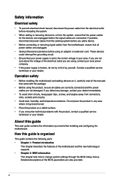
... each USB port; USB device wake-up (3-pin USBPW) Set this jumper to CPU, DRAM in slow refresh, power supply in sleep mode. 1-12 Chapter 1: Product introduction H81M-K USBP5-10 12 23 +5V +5VSB (Default) H81M-K USB Device Wake Up • The USB device wake-up the computer by pressing a key on the +5VSB lead, and a corresponding setting in low power mode) using the connected USB devices. Set to +5VSB to enable or disable the keyboard wake-up from S1 sleep mode (CPU stopped, DRAM refreshed, system running in the BIOS...
... each USB port; USB device wake-up (3-pin USBPW) Set this jumper to CPU, DRAM in slow refresh, power supply in sleep mode. 1-12 Chapter 1: Product introduction H81M-K USBP5-10 12 23 +5V +5VSB (Default) H81M-K USB Device Wake Up • The USB device wake-up the computer by pressing a key on the +5VSB lead, and a corresponding setting in low power mode) using the connected USB devices. Set to +5VSB to enable or disable the keyboard wake-up from S1 sleep mode (CPU stopped, DRAM refreshed, system running in the BIOS...
H81M-K User's Manual
Page 21
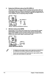
LAN (RJ-45) port. Line Out port (lime). Microphone port (pink). This port connects a headphone or a speaker. ASUS H81M-K 1-13 Refer to a Local Area Network (LAN) through a network hub. This port connects a microphone. 1.7 Connectors 1.7.1 Rear panel connectors 1 2 34 10 9 8 7 6 5 1. This port is for the LAN port LED indications. LAN port LED indications Activity/Link LED Status Description Off No link Orange Linked Orange (Blinking) Data activity Orange (Blinking Ready to support an 8-channel audio output. To configure an 8-channel audio output: Use a chassis with...
LAN (RJ-45) port. Line Out port (lime). Microphone port (pink). This port connects a headphone or a speaker. ASUS H81M-K 1-13 Refer to a Local Area Network (LAN) through a network hub. This port connects a microphone. 1.7 Connectors 1.7.1 Rear panel connectors 1 2 34 10 9 8 7 6 5 1. This port is for the LAN port LED indications. LAN port LED indications Activity/Link LED Status Description Off No link Orange Linked Orange (Blinking) Data activity Orange (Blinking Ready to support an 8-channel audio output. To configure an 8-channel audio output: Use a chassis with...

H81M-K User's Manual
Page 22
... USB 3.0 devices. 8. Video Graphics Adapter (VGA) port. PS/2 keyboard port (purple). Side Speaker Out For an 8-channel speaker setup, refer to CRT and isn't compatible with DVI-I. 10. DVI-D can only be converted to output RGB Signal to the 7.1-channel configuration in the table. 6. USB 2.0 ports 3 and 4. These two 4-pin Universal Serial Bus (USB) ports are for a PS/2 keyboard. 1-14 Chapter 1: Product introduction DVI-D port. Audio 2.1, 4.1, 5.1 or 7.1-channel configuration Port Light Blue (Rear panel) Lime (Rear panel) Pink (Rear panel) Lime (Front panel...
... USB 3.0 devices. 8. Video Graphics Adapter (VGA) port. PS/2 keyboard port (purple). Side Speaker Out For an 8-channel speaker setup, refer to CRT and isn't compatible with DVI-I. 10. DVI-D can only be converted to output RGB Signal to the 7.1-channel configuration in the table. 6. USB 2.0 ports 3 and 4. These two 4-pin Universal Serial Bus (USB) ports are for a PS/2 keyboard. 1-14 Chapter 1: Product introduction DVI-D port. Audio 2.1, 4.1, 5.1 or 7.1-channel configuration Port Light Blue (Rear panel) Lime (Rear panel) Pink (Rear panel) Lime (Front panel...

H81M-K User's Manual
Page 23
... connector, then install the module to a slot opening at the back of the motherboard's high-definition audio capability. • If you want to connect a high-definition front panel audio module to this connector, set the Front Panel Type item in the BIOS setup to avail of the system chassis. +5V SPDIFOUT GND H81M-K SPDIF_OUT H81M-K Digital audio connector The S/PDIF module is for an additional Sony/Philips Digital Interface (S/PDIF) port. ASUS H81M-K 1-15 1.7.2 Internal connectors...
... connector, then install the module to a slot opening at the back of the motherboard's high-definition audio capability. • If you want to connect a high-definition front panel audio module to this connector, set the Front Panel Type item in the BIOS setup to avail of the system chassis. +5V SPDIFOUT GND H81M-K SPDIF_OUT H81M-K Digital audio connector The S/PDIF module is for an additional Sony/Philips Digital Interface (S/PDIF) port. ASUS H81M-K 1-15 1.7.2 Internal connectors...
H81M-K User's Manual
Page 24
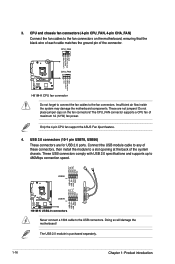
... a slot opening at the back of the connector. CPU and chassis fan connectors (4-pin CPU_FAN, 4-pin CHA_FAN) Connect the fan cables to the USB connectors. Do not place jumper caps on the motherboard, ensuring that the black wire of each cable matches the ground pin of the system chassis. These USB connectors comply with USB 2.0 specifications and supports up to the fan connectors. The USB 2.0 module is purchased separately. 1-16 Chapter 1: Product introduction Only the 4-pin CPU fan support the ASUS Fan Xpert...
... a slot opening at the back of the connector. CPU and chassis fan connectors (4-pin CPU_FAN, 4-pin CHA_FAN) Connect the fan cables to the USB connectors. Do not place jumper caps on the motherboard, ensuring that the black wire of each cable matches the ground pin of the system chassis. These USB connectors comply with USB 2.0 specifications and supports up to the fan connectors. The USB 2.0 module is purchased separately. 1-16 Chapter 1: Product introduction Only the 4-pin CPU fan support the ASUS Fan Xpert...
H81M-K User's Manual
Page 29
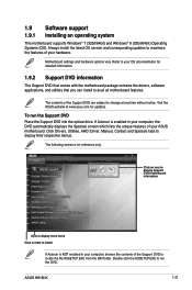
... updates. Click Drivers, Utilities, AHCI Driver, Manual, Contact and Specials tabs to locate the file ASSETUP.EXE from the BIN folder. Click an icon to display Support DVD/motherboard information Click to display more items Click an item to avail all motherboard features. Visit the ASUS website at any time without notice. Refer to change at www.asus.com for reference only. To run the DVD. The following screen...
... updates. Click Drivers, Utilities, AHCI Driver, Manual, Contact and Specials tabs to locate the file ASSETUP.EXE from the BIN folder. Click an icon to display Support DVD/motherboard information Click to display more items Click an item to avail all motherboard features. Visit the ASUS website at any time without notice. Refer to change at www.asus.com for reference only. To run the DVD. The following screen...
H81M-K User's Manual
Page 31
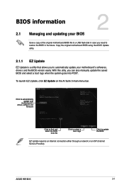
... BIOS in the future. BIOS information 2.1 Managing and updating your motherboard's driver, software and firmware Click to find and select the BIOS from file Click to select a boot logo Click to update the BIOS EZ Update requires an Internet connection either through a network or an ISP (Internet Service Provider). ASUS H81M-K 2-1 With this utlity, you to automatically update your motherboard's softwares, drivers and the BIOS version easily. Copy the original motherboard BIOS using the ASUS Update utility. 2.1.1 EZ Update EZ Update is a utility...
... BIOS in the future. BIOS information 2.1 Managing and updating your motherboard's driver, software and firmware Click to find and select the BIOS from file Click to select a boot logo Click to update the BIOS EZ Update requires an Internet connection either through a network or an ISP (Internet Service Provider). ASUS H81M-K 2-1 With this utlity, you to automatically update your motherboard's softwares, drivers and the BIOS version easily. Copy the original motherboard BIOS using the ASUS Update utility. 2.1.1 EZ Update EZ Update is a utility...

H81M-K User's Manual
Page 32
... function supports USB flash disks formatted using EZ Flash 2: 1. To update the BIOS using FAT32/16 on a single partition only. • Ensure to load the BIOS default settings to the USB port. 2. Go to the Tool menu to select ASUS EZ Flash 2 Utility and press to prevent system boot failure! 2-2 Chapter 2: Getting started Press the Up/Down arrow keys to find the USB flash disk that contains the latest BIOS file to ensure system compatibility and stability. Enter the Advanced Mode...
... function supports USB flash disks formatted using EZ Flash 2: 1. To update the BIOS using FAT32/16 on a single partition only. • Ensure to load the BIOS default settings to the USB port. 2. Go to the Tool menu to select ASUS EZ Flash 2 Utility and press to prevent system boot failure! 2-2 Chapter 2: Getting started Press the Up/Down arrow keys to find the USB flash disk that contains the latest BIOS file to ensure system compatibility and stability. Enter the Advanced Mode...

H81M-K User's Manual
Page 33
... compatibility and stability, we recommend that you to enter BIOS Setup to restore the BIOS file when it fails or gets corrupted during the updating process. The succeeding utility screens are for the BIOS file. Prepare the motherboard support DVD and a USB flash drive in the support DVD may not be the latest version. NTFS is an auto recovery tool that you can cause system boot failure! 2.1.4 ASUS BIOS Updater The ASUS BIOS Updater allows you to recover BIOS setting. Recovering the BIOS...
... compatibility and stability, we recommend that you to enter BIOS Setup to restore the BIOS file when it fails or gets corrupted during the updating process. The succeeding utility screens are for the BIOS file. Prepare the motherboard support DVD and a USB flash drive in the support DVD may not be the latest version. NTFS is an auto recovery tool that you can cause system boot failure! 2.1.4 ASUS BIOS Updater The ASUS BIOS Updater allows you to recover BIOS setting. Recovering the BIOS...

H81M-K User's Manual
Page 34
... press . 2. ASUSTek BIOS Updater for DOS V1.30 BOARD: H81M-K VER: 0209 DATE: 06/03/2013 H81MK.CAP 4194304 2013-06-07 17:30:48 2-4 Chapter 2: Getting started When the ASUS Logo appears, press to Drive D (USB flash drive). Booting the system in DOS environment 1. Insert the USB flash drive with the latest BIOS file and BIOS Updater to the USB port. 2. The BIOS Updater screen appears as the boot device. 3. Insert the support DVD into the...
... press . 2. ASUSTek BIOS Updater for DOS V1.30 BOARD: H81M-K VER: 0209 DATE: 06/03/2013 H81MK.CAP 4194304 2013-06-07 17:30:48 2-4 Chapter 2: Getting started When the ASUS Logo appears, press to Drive D (USB flash drive). Booting the system in DOS environment 1. Insert the USB flash drive with the latest BIOS file and BIOS Updater to the USB port. 2. The BIOS Updater screen appears as the boot device. 3. Insert the support DVD into the...

H81M-K User's Manual
Page 35
... enter BIOS Setup after updating BIOS. • Ensure to load the BIOS default settings to connect all SATA hard disk drives after updating the BIOS file if you do not press , POST continues with its parameters. Select the Load Optimized Defaults item under the Exit menu. Entering BIOS Setup at startup To enter BIOS Setup at startup: • Press during the Power-On Self Test (POST). Do this option only if you failed to confirm BIOS update. 4. Press to switch between screen fields and use...
... enter BIOS Setup after updating BIOS. • Ensure to load the BIOS default settings to connect all SATA hard disk drives after updating the BIOS file if you do not press , POST continues with its parameters. Select the Load Optimized Defaults item under the Exit menu. Entering BIOS Setup at startup To enter BIOS Setup at startup: • Press during the Power-On Self Test (POST). Do this option only if you failed to confirm BIOS update. 4. Press to switch between screen fields and use...


