User Guide
Page 4
... the product, contact a qualified service technician or your dealer immediately. • To avoid short circuits, keep paper clips, screws, and staples away from connectors, slots, sockets and circuitry. • Avoid dust, humidity, and temperature extremes.
... the product, contact a qualified service technician or your dealer immediately. • To avoid short circuits, keep paper clips, screws, and staples away from connectors, slots, sockets and circuitry. • Avoid dust, humidity, and temperature extremes.
User Guide
Page 6
... Supports DVI-D with max. Supports D-SUB with max.resolution of 1920 x 1200 @60Hz - H81M-C specifications summary CPU Chipset Memory Graphics Expansion slots Storage Audio LAN LGA1150 socket for 4th Generation Intel® CoreTM i7/i5/i3, Pentium®, Celeron® Processors Supports...a chassis with HD audio module in the front panel to www.asus.com for Intel® CPU support list. Package contents Check your motherboard package for the following items. Motherboard Cables Accessories Application DVD Documentation ASUS H81M-C motherboard 2 x Serial ATA 6.0 Gb/s cables 1 x ...
... Supports DVI-D with max. Supports D-SUB with max.resolution of 1920 x 1200 @60Hz - H81M-C specifications summary CPU Chipset Memory Graphics Expansion slots Storage Audio LAN LGA1150 socket for 4th Generation Intel® CoreTM i7/i5/i3, Pentium®, Celeron® Processors Supports...a chassis with HD audio module in the front panel to www.asus.com for Intel® CPU support list. Package contents Check your motherboard package for the following items. Motherboard Cables Accessories Application DVD Documentation ASUS H81M-C motherboard 2 x Serial ATA 6.0 Gb/s cables 1 x ...

User Guide
Page 9
...physical injury and damage to ensure that the ATX power supply is switched off or the power cord is detached from the wall socket before touching any motherboard settings. • Unplug the power cord from the power supply. Failure to do so may cause ...your chassis to motherboard components. 1.2.1 Placement direction When installing the motherboard, place it on a grounded antistatic pad or in the correct orientation. ASUS H81M-C 1-1 Failure to do so can damage the motherboard. Product introduction 1 1.1 Before you proceed Take note of the following precautions before you ...
...physical injury and damage to ensure that the ATX power supply is switched off or the power cord is detached from the wall socket before touching any motherboard settings. • Unplug the power cord from the power supply. Failure to do so may cause ...your chassis to motherboard components. 1.2.1 Placement direction When installing the motherboard, place it on a grounded antistatic pad or in the correct orientation. ASUS H81M-C 1-1 Failure to do so can damage the motherboard. Product introduction 1 1.1 Before you proceed Take note of the following precautions before you ...

User Guide
Page 11
...fan connectors (4-pin CPU_FAN, 4-pin CHA_FAN) 4. Clear RTC RAM (3-pin CLRTC) 12. USB 2.0 connectors (10-1 pin USB910, USB1112) 13. H81M-C H81M-C CPU socket LGA1150 ASUS H81M-C 1-3 Intel® H81 Serial ATA 3.0Gb/s connector (7-pin SATA3G_1~2 [dark brown]) 7. TPM header (20-1 pin TPM) 14. Front ...1-18 1-15 1-18 1-12 1-10 1-17 1-14 1-19 1-15 1-17 1.3 Central Processing Unit (CPU) This motherboard comes with a surface mount LGA1150 socket designed for the Intel® 4th generation Core™ i7 / Core™ i5 / Core™ i3, Pentium® , Celeron® processors. Intel...
...fan connectors (4-pin CPU_FAN, 4-pin CHA_FAN) 4. Clear RTC RAM (3-pin CLRTC) 12. USB 2.0 connectors (10-1 pin USB910, USB1112) 13. H81M-C H81M-C CPU socket LGA1150 ASUS H81M-C 1-3 Intel® H81 Serial ATA 3.0Gb/s connector (7-pin SATA3G_1~2 [dark brown]) 7. TPM header (20-1 pin TPM) 14. Front ...1-18 1-15 1-18 1-12 1-10 1-17 1-14 1-19 1-15 1-17 1.3 Central Processing Unit (CPU) This motherboard comes with a surface mount LGA1150 socket designed for the Intel® 4th generation Core™ i7 / Core™ i5 / Core™ i3, Pentium® , Celeron® processors. Intel...
User Guide
Page 12
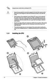
..., ensure that you see any damage to the socket contacts resulting from incorrect CPU installation/removal, or misplacement/loss/incorrect removal of repair only if the damage is on the socket and the socket contacts are not bent. ASUS will shoulder the cost of the PnP cap. ...1.3.1 Installing the CPU 1 A B 2 3 1-4 Chapter 1: Product introduction DO NOT install a CPU designed for the LGA1150 socket only. Unplug all power cables before installing the...
..., ensure that you see any damage to the socket contacts resulting from incorrect CPU installation/removal, or misplacement/loss/incorrect removal of repair only if the damage is on the socket and the socket contacts are not bent. ASUS will shoulder the cost of the PnP cap. ...1.3.1 Installing the CPU 1 A B 2 3 1-4 Chapter 1: Product introduction DO NOT install a CPU designed for the LGA1150 socket only. Unplug all power cables before installing the...
User Guide
Page 15
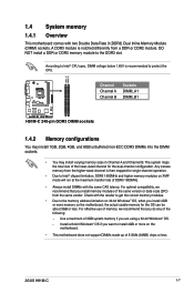
... install 1GB, 2GB, 4GB, and 8GB unbuffered non-ECC DDR3 DIMMs into the DIMM sockets. • You may install varying memory sizes in Channel A and Channel B. Any excess memory from a DDR or DDR2 module. ASUS H81M-C 1-7 The system maps the total size of the lower-sized channel for the OS ... OS, when you do any of DDR3 1600MHz. • Always install DIMMs with two Double Data Rate 3 (DDR3) Dual Inline Memory Module (DIMM) sockets. According to Intel® CPU spec, DIMM voltage below 1.65V is then mapped for single-channel operation. • Due to the memory address limitation on...
... install 1GB, 2GB, 4GB, and 8GB unbuffered non-ECC DDR3 DIMMs into the DIMM sockets. • You may install varying memory sizes in Channel A and Channel B. Any excess memory from a DDR or DDR2 module. ASUS H81M-C 1-7 The system maps the total size of the lower-sized channel for the OS ... OS, when you do any of DDR3 1600MHz. • Always install DIMMs with two Double Data Rate 3 (DDR3) Dual Inline Memory Module (DIMM) sockets. According to Intel® CPU spec, DIMM voltage below 1.65V is then mapped for single-channel operation. • Due to the memory address limitation on...
User Guide
Page 16
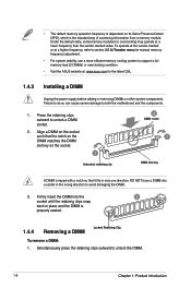
... DIMM is properly seated. 1.4.4 Removing a DIMM Locked Retaining Clip To remove a DIMM: 1. • The default memory operation frequency is dependent on the socket. 1 Unlocked retaining clip 2 DIMM notch 1 DIMM slot key A DIMM is keyed with a notch so that it fits in the wrong direction to avoid...support a full memory load (2 DIMMs) or overclocking condition. • Visit the ASUS website at: www.asus.com for overclocking may operate at a lower frequency than the vendor-marked value. Align a DIMM on the socket such that the notch on the DIMM matches the DIMM slot key on its ...
... DIMM is properly seated. 1.4.4 Removing a DIMM Locked Retaining Clip To remove a DIMM: 1. • The default memory operation frequency is dependent on the socket. 1 Unlocked retaining clip 2 DIMM notch 1 DIMM slot key A DIMM is keyed with a notch so that it fits in the wrong direction to avoid...support a full memory load (2 DIMMs) or overclocking condition. • Visit the ASUS website at: www.asus.com for overclocking may operate at a lower frequency than the vendor-marked value. Align a DIMM on the socket such that the notch on the DIMM matches the DIMM slot key on its ...
User Guide
Page 17
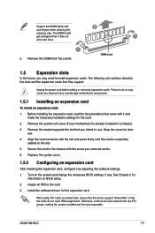
.... Assign an IRQ to the chassis with the screw you physical injury and damage motherboard components. 1.5.1 Installing an expansion card To install an expansion card: 1. ASUS H81M-C 1-9 Replace the system cover. 1.5.2 Configuring an expansion card After installing the expansion card, configure it flips out 1 with extra force. 1 2. See Chapter 2 for the card... on shared slots, ensure that the drivers support "Share IRQ" or that the cards do so may need IRQ assignments. Remove the DIMM from the socket.
.... Assign an IRQ to the chassis with the screw you physical injury and damage motherboard components. 1.5.1 Installing an expansion card To install an expansion card: 1. ASUS H81M-C 1-9 Replace the system cover. 1.5.2 Configuring an expansion card After installing the expansion card, configure it flips out 1 with extra force. 1 2. See Chapter 2 for the card... on shared slots, ensure that the drivers support "Share IRQ" or that the cards do so may need IRQ assignments. Remove the DIMM from the socket.


