
User Manual
Page 9
... @60Hz Supports single-link DVI with max. F1A75-M PRO specifications summary APU Chipset Memory Graphics Expansion slots Storage / RAID LAN AMD® A- & E2- series accelerated processors with AMD® Radeon™ HD 6000 series graphics, up to www.asus.com for the discrete GPUs that support Dual ...Graphics. ** The HDMI and DVI-D output ports cannot work simultaneously. 2 x PCIe 2.0 x16 slots with max. resolution up to 4 CPU cores, FM1 package AMD® Turbo Core Technology 2.0 support * The AMD® Turbo Core...
... @60Hz Supports single-link DVI with max. F1A75-M PRO specifications summary APU Chipset Memory Graphics Expansion slots Storage / RAID LAN AMD® A- & E2- series accelerated processors with AMD® Radeon™ HD 6000 series graphics, up to www.asus.com for the discrete GPUs that support Dual ...Graphics. ** The HDMI and DVI-D output ports cannot work simultaneously. 2 x PCIe 2.0 x16 slots with max. resolution up to 4 CPU cores, FM1 package AMD® Turbo Core Technology 2.0 support * The AMD® Turbo Core...

User Manual
Page 20
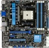
... 8 9 10 2 EATXPWR CHA_FAN2 24.4cm(9.6in) CHA_FAN1 ICS477D AUDIO RTL 8111E Super I/O PWR_FAN Lithium Cell CMOS Power PCIEX16_1 F1A75-M PRO PCIEX1_1 TPU PCI1 AMD® A75 1 SB_PWR 11 12 SATA6G_2 SATA6G_4 SATA6G_6 SATA6G_1 SATA6G_3 SATA6G_5 ALC 892 AAFP SPDIF_OUT PCIEX16_2 USB78 COM1 USB910 USB34 USB56... USB3_56 CLRTC 32Mb BIOS PANEL 13 19 18 17 16 15 14 1.5.4 Layout contents Connectors/Jumpers/Slots/LED 1. AMD FM1 socket 4. switch 10. System panel connector (20-8 pin PANEL) 1-12 14. USB 3.0 connector (20-1 pin USB3_34) 1-28 16....
... 8 9 10 2 EATXPWR CHA_FAN2 24.4cm(9.6in) CHA_FAN1 ICS477D AUDIO RTL 8111E Super I/O PWR_FAN Lithium Cell CMOS Power PCIEX16_1 F1A75-M PRO PCIEX1_1 TPU PCI1 AMD® A75 1 SB_PWR 11 12 SATA6G_2 SATA6G_4 SATA6G_6 SATA6G_1 SATA6G_3 SATA6G_5 ALC 892 AAFP SPDIF_OUT PCIEX16_2 USB78 COM1 USB910 USB34 USB56... USB3_56 CLRTC 32Mb BIOS PANEL 13 19 18 17 16 15 14 1.5.4 Layout contents Connectors/Jumpers/Slots/LED 1. AMD FM1 socket 4. switch 10. System panel connector (20-8 pin PANEL) 1-12 14. USB 3.0 connector (20-1 pin USB3_34) 1-28 16....

User Manual
Page 21
DO NOT force the APU into the socket to prevent bending the pins and damaging the APU! F1A75-M PRO F1A75-M PRO processor socket FM1 2. Small triangle Gold triangle ASUS F1A75-M PRO 1-9 Locate the FM1 socket on the motherboard. Socket lever Ensure that the socket lever is lifted up to prevent bending the .... 4. Position the APU above the socket such that you use a APU designed for AMD® A- & E2- The APU fits only in only one correct orientation. series accelerated processors with AMD® Radeon™ HD 6000 series graphics. Ensure that the APU corner with the ...
DO NOT force the APU into the socket to prevent bending the pins and damaging the APU! F1A75-M PRO F1A75-M PRO processor socket FM1 2. Small triangle Gold triangle ASUS F1A75-M PRO 1-9 Locate the FM1 socket on the motherboard. Socket lever Ensure that the socket lever is lifted up to prevent bending the .... 4. Position the APU above the socket such that you use a APU designed for AMD® A- & E2- The APU fits only in only one correct orientation. series accelerated processors with AMD® Radeon™ HD 6000 series graphics. Ensure that the APU corner with the ...

User Manual
Page 9
...cores, FM1 package AMD® Turbo Core Technology 2.0 support * The AMD® Turbo Core Technology 2.0 support depends on the next page) ix resolution up to 1920 x 1080 @60Hz Supports single-link DVI with max. Integrated AMD®... Radeon™ HD 6000 series graphics in the market. ** Refer to www.asus.com for the latest Memory QVL (Qualified Vendors List). ***...operating system may only recognize less than 3GB. F1A75-M PRO specifications summary APU Chipset Memory Graphics Expansion slots Storage / RAID LAN...
...cores, FM1 package AMD® Turbo Core Technology 2.0 support * The AMD® Turbo Core Technology 2.0 support depends on the next page) ix resolution up to 1920 x 1080 @60Hz Supports single-link DVI with max. Integrated AMD®... Radeon™ HD 6000 series graphics in the market. ** Refer to www.asus.com for the latest Memory QVL (Qualified Vendors List). ***...operating system may only recognize less than 3GB. F1A75-M PRO specifications summary APU Chipset Memory Graphics Expansion slots Storage / RAID LAN...

User Manual
Page 20
...) 1-25 19. AMD FM1 socket 4. TPU switch 9. SATA 6.0Gb/s connectors (7-pin SATA6G_1~6) 1-10 13. DRAM_LED TPU EPU 5 6 7 8 9 10 2 EATXPWR CHA_FAN2 24.4cm(9.6in) CHA_FAN1 ICS477D AUDIO RTL 8111E Super I/O PWR_FAN Lithium Cell CMOS Power PCIEX16_1 F1A75-M PRO PCIEX1_1 TPU PCI1 AMD® A75 1 SB_PWR...) 1-28 15. 1.5.3 Motherboard layout 1 2 13 24.4cm(9.6in) KB_USB3_34 SPDIF_O2 _HDMI ASM 1042 EATX12V DIGI+VRM EPU CPU_FAN SOCKET FM1 DVI_VGA USB3_12 LAN1_USB12 DDR3 DIMM_A1 (64bit, 240-pin module) DDR3 DIMM_A2 (64bit, 240-pin module) DDR3 DIMM_B1 (64bit, 240-pin module...
...) 1-25 19. AMD FM1 socket 4. TPU switch 9. SATA 6.0Gb/s connectors (7-pin SATA6G_1~6) 1-10 13. DRAM_LED TPU EPU 5 6 7 8 9 10 2 EATXPWR CHA_FAN2 24.4cm(9.6in) CHA_FAN1 ICS477D AUDIO RTL 8111E Super I/O PWR_FAN Lithium Cell CMOS Power PCIEX16_1 F1A75-M PRO PCIEX1_1 TPU PCI1 AMD® A75 1 SB_PWR...) 1-28 15. 1.5.3 Motherboard layout 1 2 13 24.4cm(9.6in) KB_USB3_34 SPDIF_O2 _HDMI ASM 1042 EATX12V DIGI+VRM EPU CPU_FAN SOCKET FM1 DVI_VGA USB3_12 LAN1_USB12 DDR3 DIMM_A1 (64bit, 240-pin module) DDR3 DIMM_A2 (64bit, 240-pin module) DDR3 DIMM_B1 (64bit, 240-pin module...

User Manual
Page 21
... Ensure that the APU corner with the gold triangle matches the socket corner with AMD® Radeon™ HD 6000 series graphics. otherwise, the APU will not fit in one correct orientation. Small triangle Gold triangle ASUS F1A75-M PRO 1-9 F1A75-M PRO F1A75-M PRO processor socket FM1 2. The APU fits only in completely. 3. Position the APU above the socket such...
... Ensure that the APU corner with the gold triangle matches the socket corner with AMD® Radeon™ HD 6000 series graphics. otherwise, the APU will not fit in one correct orientation. Small triangle Gold triangle ASUS F1A75-M PRO 1-9 F1A75-M PRO F1A75-M PRO processor socket FM1 2. The APU fits only in completely. 3. Position the APU above the socket such...


