CUSL2 User Manual
Page 4
... 61 4.4.2 I/O Device Configuration 64 4.4.3 PCI Configuration 66 4.4.4 Shadow Configuration 68 4 ASUS CUSL2 User's Manual FEATURES 8 2.1 The ASUS CUSL2 8 2.2 CUSL2 Motherboard Components 12 3. HARDWARE SETUP 14 3.1 CUSL2 Motherboard Layout 14 3.2 Layout Contents 15 3.3 Hardware Setup Procedure 17 3.4 Motherboard Settings 17 3.5 System Memory (DIMM 24 3.5.1 General DIMM Notes 24 3.5.2 Memory Installation 25 3.6 Central Processing Unit (CPU 26 3.7 Expansion Cards 27...
... 61 4.4.2 I/O Device Configuration 64 4.4.3 PCI Configuration 66 4.4.4 Shadow Configuration 68 4 ASUS CUSL2 User's Manual FEATURES 8 2.1 The ASUS CUSL2 8 2.2 CUSL2 Motherboard Components 12 3. HARDWARE SETUP 14 3.1 CUSL2 Motherboard Layout 14 3.2 Layout Contents 15 3.3 Hardware Setup Procedure 17 3.4 Motherboard Settings 17 3.5 System Memory (DIMM 24 3.5.1 General DIMM Notes 24 3.5.2 Memory Installation 25 3.6 Central Processing Unit (CPU 26 3.7 Expansion Cards 27...
CUSL2 User Manual
Page 8
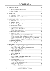
... Intel® 815E chipset supports a 66/100/133 Front Side Bus (FSB), up to 512MB of the processor's external frequency. 8 ASUS CUSL2 User's Manual able in 64, 128, 256, 512MB densities) up to allow manual adjustment of PC100/PC133 SDRAM, and AGP Pro/ 4X...AGP 2X. FEATURES Specifications 2. Backward compatible to 4MB of 266MB/sec - FEATURES 2.1 The ASUS CUSL2 The ASUS CUSL2 motherboard is enabled. twice the maximum bandwidth of the PCI bus. • PC100/PC133 Memory Support: Equipped with a bandwidth of 133MHz SDRAM display cache. • UltraDMA33/66/100 ...
... Intel® 815E chipset supports a 66/100/133 Front Side Bus (FSB), up to 512MB of the processor's external frequency. 8 ASUS CUSL2 User's Manual able in 64, 128, 256, 512MB densities) up to allow manual adjustment of PC100/PC133 SDRAM, and AGP Pro/ 4X...AGP 2X. FEATURES Specifications 2. Backward compatible to 4MB of 266MB/sec - FEATURES 2.1 The ASUS CUSL2 The ASUS CUSL2 motherboard is enabled. twice the maximum bandwidth of the PCI bus. • PC100/PC133 Memory Support: Equipped with a bandwidth of 133MHz SDRAM display cache. • UltraDMA33/66/100 ...
CUSL2 User Manual
Page 9
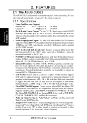
...not to damage the motherboard, peripherals, and/or components. • One Touch Management: Supports an optional ASUS iPanel, an easy to turn OFF the power before plugging and unplugging devices so as xDSL. •...Around-the-Clock Intrusion Detection: Chassis intrusion circuitry can also be directed from PCI master busses to the memory and processor. • Onboard LED: The onboard LED will light up to physically transport commands and information...interface which provides more control and protection over the motherboard. ASUS CUSL2 User's Manual 9 2. FEATURES Specifications 2.
...not to damage the motherboard, peripherals, and/or components. • One Touch Management: Supports an optional ASUS iPanel, an easy to turn OFF the power before plugging and unplugging devices so as xDSL. •...Around-the-Clock Intrusion Detection: Chassis intrusion circuitry can also be directed from PCI master busses to the memory and processor. • Onboard LED: The onboard LED will light up to physically transport commands and information...interface which provides more control and protection over the motherboard. ASUS CUSL2 User's Manual 9 2. FEATURES Specifications 2.
CUSL2 User Manual
Page 10
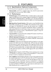
... with 3D sound circuitry and sample rate conversion from PCI master buses to memory and processor. • SDRAM Optimized Performance: This motherboard supports PC133-compliant Synchronous Dynamic Random Access Memory (SDRAM), which increases the data transfer rate to 100MB/s. The new PC... New Compliancy: Both the BIOS and hardware levels of ACPI, an ACPI-supported OS, such as required by PC 99. 10 ASUS CUSL2 User's Manual 2. FEATURES Performance 2. FEATURES 2.1.2 Specifications-Optional Components The following high-level goals: support for Plug and Play compatibility ...
... with 3D sound circuitry and sample rate conversion from PCI master buses to memory and processor. • SDRAM Optimized Performance: This motherboard supports PC133-compliant Synchronous Dynamic Random Access Memory (SDRAM), which increases the data transfer rate to 100MB/s. The new PC... New Compliancy: Both the BIOS and hardware levels of ACPI, an ACPI-supported OS, such as required by PC 99. 10 ASUS CUSL2 User's Manual 2. FEATURES Performance 2. FEATURES 2.1.2 Specifications-Optional Components The following high-level goals: support for Plug and Play compatibility ...
CUSL2 User Manual
Page 11
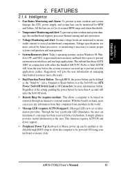
...Alert: Today's operating systems, such as the Soft-Off (see ATX Power / Soft-Off Switch Lead in conjunction with either the bundled ASUS PC Probe or Intel LDCM will enter the Soft-Off mode. • Remote Ring On (requires modem): This allows a computer to critical... Power Up: Keyboard or Mouse power up to present enormous user interfaces and run large applications. ASUS CUSL2 User's Manual 11 FEATURES Intelligence 2. Voltage specifications are set for more memory and hard drive space to prevent possible application crashes. Through the way a particular LED illuminates, the...
...Alert: Today's operating systems, such as the Soft-Off (see ATX Power / Soft-Off Switch Lead in conjunction with either the bundled ASUS PC Probe or Intel LDCM will enter the Soft-Off mode. • Remote Ring On (requires modem): This allows a computer to critical... Power Up: Keyboard or Mouse power up to present enormous user interfaces and run large applications. ASUS CUSL2 User's Manual 11 FEATURES Intelligence 2. Voltage specifications are set for more memory and hard drive space to prevent possible application crashes. Through the way a particular LED illuminates, the...
CUSL2 User Manual
Page 12
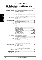
... 1 Serial COM2 Header 7 1 ASUS iPanel Connector 8 1 Parallel Port Connector Top) 23 1 Serial COM1 Port Connector Bottom) 24 2 USB Port Connectors 25 1 PS/2 Mouse Connector Top) 26 1 PS/2 Keyboard Connector Bottom) 26 3D Graphics Graphics and Memory Controller Hub 1 VGA Monitor Output ...Connector 9 Hardware Monitoring System Voltage Monitoring (integrated in ASUS ASIC) ....... 13 3 Fan Power and Speed Monitoring Connectors Power ATX Power Supply Connector 21 Special Feature Onboard LED 16 Form Factor ATX 12 ASUS CUSL2 User's Manual 2. Location Processor Support Socket 370 for...
... 1 Serial COM2 Header 7 1 ASUS iPanel Connector 8 1 Parallel Port Connector Top) 23 1 Serial COM1 Port Connector Bottom) 24 2 USB Port Connectors 25 1 PS/2 Mouse Connector Top) 26 1 PS/2 Keyboard Connector Bottom) 26 3D Graphics Graphics and Memory Controller Hub 1 VGA Monitor Output ...Connector 9 Hardware Monitoring System Voltage Monitoring (integrated in ASUS ASIC) ....... 13 3 Fan Power and Speed Monitoring Connectors Power ATX Power Supply Connector 21 Special Feature Onboard LED 16 Form Factor ATX 12 ASUS CUSL2 User's Manual 2. Location Processor Support Socket 370 for...
CUSL2 User Manual
Page 14
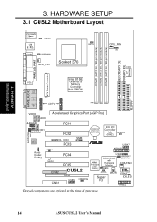
... module) SECONDARY IDE PRIMARY IDE DIP Switches PARALLEL PORT ATX Power Connector GAME_AUDIO VGA Line Out Line In Mic In LCDTV Intel 815E Graphics & Memory Controller Hub (GMCH) ROW 0 1 2 3 4 5 VIDEO Accelerated Graphics Port (AGP Pro) AUX AAPANEL CD1 MODEM PCI1 PCI2 CR2032 3V...Audio Codec WOL_CON SMB PCI3 ® USB47 Audio Codec Setting JTPWR PLED2 CNR2 CNR1 AFPANEL PCI4 PCI5 CUSL2 PCI6 USB56 USBPWR56 4Mbit Firmware Hub (FWH) USB2 USBPWR47 ASUS ASIC USBPWR2 with Hardware CHA_FAN Monitor JEN ACHA Super I/O WOR COM2 IDELED PANEL Grayed components are ...
... module) SECONDARY IDE PRIMARY IDE DIP Switches PARALLEL PORT ATX Power Connector GAME_AUDIO VGA Line Out Line In Mic In LCDTV Intel 815E Graphics & Memory Controller Hub (GMCH) ROW 0 1 2 3 4 5 VIDEO Accelerated Graphics Port (AGP Pro) AUX AAPANEL CD1 MODEM PCI1 PCI2 CR2032 3V...Audio Codec WOL_CON SMB PCI3 ® USB47 Audio Codec Setting JTPWR PLED2 CNR2 CNR1 AFPANEL PCI4 PCI5 CUSL2 PCI6 USB56 USBPWR56 4Mbit Firmware Hub (FWH) USB2 USBPWR47 ASUS ASIC USBPWR2 with Hardware CHA_FAN Monitor JEN ACHA Super I/O WOR COM2 IDELED PANEL Grayed components are ...
CUSL2 User Manual
Page 15
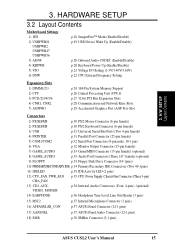
...40V/3.60V) p.22 CPU External Frequency Setting Expansion Slots 1) DIMM1/2/3 2) CPU 3) PCI1/2/3/4/5/6 4) CNR1, CNR2 5) AGPPRO p.24 168-Pin System Memory Support p.26 Central Processing Unit (CPU)6 p.27 32-bit PCI Bus Expansion Slots p.28 Communication and Network Riser Slots p.29 Accelerated Graphics Port ...Headphone True-Level Line Out Header (3 pins) 15) MIC2 p.37 Internal Microphone Connector (3 pins) 16) AFPANEL/IR_CON p.37 ASUS iPanel Connector (12-1 pins) 17) AAPANEL p.37 ASUS iPanel Audio Connector (12-1 pins) 18) SMB p.38 SMBus Connector (5-1 pins) ASUS CUSL2 User's Manual 15
...40V/3.60V) p.22 CPU External Frequency Setting Expansion Slots 1) DIMM1/2/3 2) CPU 3) PCI1/2/3/4/5/6 4) CNR1, CNR2 5) AGPPRO p.24 168-Pin System Memory Support p.26 Central Processing Unit (CPU)6 p.27 32-bit PCI Bus Expansion Slots p.28 Communication and Network Riser Slots p.29 Accelerated Graphics Port ...Headphone True-Level Line Out Header (3 pins) 15) MIC2 p.37 Internal Microphone Connector (3 pins) 16) AFPANEL/IR_CON p.37 ASUS iPanel Connector (12-1 pins) 17) AAPANEL p.37 ASUS iPanel Audio Connector (12-1 pins) 18) SMB p.38 SMBus Connector (5-1 pins) ASUS CUSL2 User's Manual 15
CUSL2 User Manual
Page 17
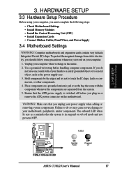
... LED when lit acts as the power supply case. 3. If you must complete the following steps: • Check Motherboard Settings • Install Memory Modules • Install the Central Processing Unit (CPU) • Install Expansion Cards • Connect Ribbon Cables, Panel Wires, and Power Supply...or to touch the IC chips, leads or connectors, or other components. 4. H/W SETUP Motherboard Settings ® CUSL2 CUSL2 Onboard LED PLED2 ON Standby Power OFF Powered Off ASUS CUSL2 User's Manual 17 WARNING! 3. To protect them against damage from the system. 5. Hold components by the ...
... LED when lit acts as the power supply case. 3. If you must complete the following steps: • Check Motherboard Settings • Install Memory Modules • Install the Central Processing Unit (CPU) • Install Expansion Cards • Connect Ribbon Cables, Panel Wires, and Power Supply...or to touch the IC chips, leads or connectors, or other components. 4. H/W SETUP Motherboard Settings ® CUSL2 CUSL2 Onboard LED PLED2 ON Standby Power OFF Powered Off ASUS CUSL2 User's Manual 17 WARNING! 3. To protect them against damage from the system. 5. Hold components by the ...
CUSL2 User Manual
Page 24
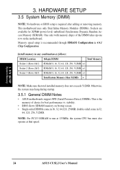
... after adding or removing memory. H/W SETUP System Memory 24 ASUS CUSL2 User's Manual Install memory in 16, 32, 64,128, 256MB; stability. • BIOS shows SDRAM memory on the motherboard. Sockets are available for best performance vs. One side (with memory chips) of choice for 3.3Volt (power level) unbuffered Synchronous Dynamic Random Access Memory (SDRAM). 3. This motherboard uses...
... after adding or removing memory. H/W SETUP System Memory 24 ASUS CUSL2 User's Manual Install memory in 16, 32, 64,128, 256MB; stability. • BIOS shows SDRAM memory on the motherboard. Sockets are available for best performance vs. One side (with memory chips) of choice for 3.3Volt (power level) unbuffered Synchronous Dynamic Random Access Memory (SDRAM). 3. This motherboard uses...
CUSL2 User Manual
Page 25
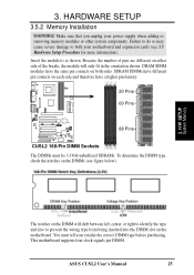
... notches on the DIMM will only fit in the orientation shown. HARDWARE SETUP 3.5.2 Memory Installation WARNING! Insert the module(s) as shown. Make sure that you unplug your motherboard and expansion cards (see figure below). 3. Because the number of pins ... slot on either side of the breaks, the module will shift between left, center, or right to identify the type and also to both sides. ASUS CUSL2 User's Manual 25 SDRAM DIMMs have different pin contacts on each side and therefore have the same pin contacts on the DIMMs (see 3.3 Hardware Setup...
... notches on the DIMM will only fit in the orientation shown. HARDWARE SETUP 3.5.2 Memory Installation WARNING! Insert the module(s) as shown. Make sure that you unplug your motherboard and expansion cards (see figure below). 3. Because the number of pins ... slot on either side of the breaks, the module will shift between left, center, or right to identify the type and also to both sides. ASUS CUSL2 User's Manual 25 SDRAM DIMMs have different pin contacts on each side and therefore have the same pin contacts on the DIMMs (see 3.3 Hardware Setup...
CUSL2 User Manual
Page 29
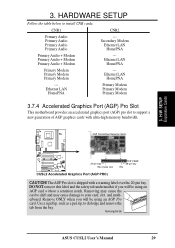
H/W SETUP Expansion Cards ® CUSL2 20-pin bay Rib (inside slot) CUSL2 Accelerated Graphics Port (AGP PRO) TOP VIEW 28-pin bay Rib CAUTION! Remove ONLY when you will be using an AGP Pro card. CNR1 CNR2 ... cards with a warning label over the 20-pin bay. AGP Card without a retention notch. The AGP Pro slot is shipped with ultra-high memory bandwidth. Removing the tab ASUS CUSL2 User's Manual 29 Removing may cause the card to shift and may cause damage to dislodge and remove the tab from the bay...
H/W SETUP Expansion Cards ® CUSL2 20-pin bay Rib (inside slot) CUSL2 Accelerated Graphics Port (AGP PRO) TOP VIEW 28-pin bay Rib CAUTION! Remove ONLY when you will be using an AGP Pro card. CNR1 CNR2 ... cards with a warning label over the 20-pin bay. AGP Card without a retention notch. The AGP Pro slot is shipped with ultra-high memory bandwidth. Removing the tab ASUS CUSL2 User's Manual 29 Removing may cause the card to shift and may cause damage to dislodge and remove the tab from the bay...
CUSL2 User Manual
Page 43
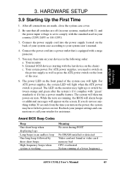
... voltage is pressed. Be sure that is working Meaning No error during POST No DRAM installed or detected Video card not found or video card memory bad CPU overheated System running , the BIOS will alarm beeps or additional messages will light when the ATX power switch is set to your system... your jumper settings and connections or call your country (220V-240V or 110-120V). 3. Your system power. After all switches are running at a lower frequency ASUS CUSL2 User's Manual 43 External SCSI devices (starting with "green" standards or if it has a power standby feature. 3.
... voltage is pressed. Be sure that is working Meaning No error during POST No DRAM installed or detected Video card not found or video card memory bad CPU overheated System running , the BIOS will alarm beeps or additional messages will light when the ATX power switch is set to your system... your jumper settings and connections or call your country (220V-240V or 110-120V). 3. Your system power. After all switches are running at a lower frequency ASUS CUSL2 User's Manual 43 External SCSI devices (starting with "green" standards or if it has a power standby feature. 3.
CUSL2 User Manual
Page 45
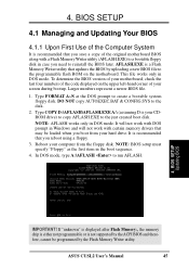
...) to copy AFLASH.EXE to the just created boot disk. ASUS CUSL2 User's Manual 45 In DOS mode, type A:\AFLASH to the disk. 2. It will not work with DOS prompt in Windows and will not work with a Flash Memory Writer utility (AFLASH.EXE) to the programmable flash ROM on ...file to a bootable floppy disk in DOS mode. AFLASH.EXE is your screen during bootup. Type COPY D:\AFLASH\AFLASH.EXE A:\ (assuming D is a Flash Memory Writer utility that you need to create a bootable system floppy disk. 4. Reboot your computer from your hard drive. Type FORMAT A:/S at the DOS prompt ...
...) to copy AFLASH.EXE to the just created boot disk. ASUS CUSL2 User's Manual 45 In DOS mode, type A:\AFLASH to the disk. 2. It will not work with DOS prompt in Windows and will not work with a Flash Memory Writer utility (AFLASH.EXE) to the programmable flash ROM on ...file to a bootable floppy disk in DOS mode. AFLASH.EXE is your screen during bootup. Type COPY D:\AFLASH\AFLASH.EXE A:\ (assuming D is a Flash Memory Writer utility that you need to create a bootable system floppy disk. 4. Reboot your computer from your hard drive. Type FORMAT A:/S at the DOS prompt ...
CUSL2 User Manual
Page 48
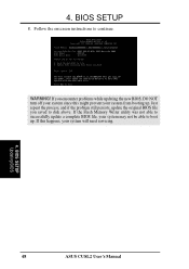
If you saved to successfully update a complete BIOS file, your system from booting up . Just repeat the process, and if the problem still persists, update the original BIOS file you encounter problems while updating the new BIOS, DO NOT turn off your system since this happens, your system will need servicing. 4. If the Flash Memory Writer utility was not able to disk above. BIOS SETUP Updating BIOS 48 ASUS CUSL2 User's Manual Follow the onscreen instructions to boot up . WARNING! 4. BIOS SETUP 8. If this might prevent your system may not be able to continue.
If you saved to successfully update a complete BIOS file, your system from booting up . Just repeat the process, and if the problem still persists, update the original BIOS file you encounter problems while updating the new BIOS, DO NOT turn off your system since this happens, your system will need servicing. 4. If the Flash Memory Writer utility was not able to disk above. BIOS SETUP Updating BIOS 48 ASUS CUSL2 User's Manual Follow the onscreen instructions to boot up . WARNING! 4. BIOS SETUP 8. If this might prevent your system may not be able to continue.
CUSL2 User Manual
Page 57
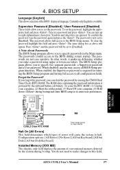
...points to Clear CMOS Halt On [All Errors] This field determines which types of errors will cause the system to eight alphanumeric characters. ASUS CUSL2 User's Manual 57 Supervisor Password [Disabled] / User Password [Disabled] These fields allow you to [Disabled]. Press and the password will ... menus. This password allows full access to all BIOS Setup program functions. BIOS SETUP Language [English] This allows selection of conventional memory detected by erasing the CMOS Real Time Clock (RTC) RAM. When enabled, the Supervisor password is now set the password, highlight...
...points to Clear CMOS Halt On [All Errors] This field determines which types of errors will cause the system to eight alphanumeric characters. ASUS CUSL2 User's Manual 57 Supervisor Password [Disabled] / User Password [Disabled] These fields allow you to [Disabled]. Press and the password will ... menus. This password allows full access to all BIOS Setup program functions. BIOS SETUP Language [English] This allows selection of conventional memory detected by erasing the CMOS Real Time Clock (RTC) RAM. When enabled, the Supervisor password is now set the password, highlight...
CUSL2 User Manual
Page 58
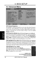
... frequency. You may cause the system to [133:133:33] 58 ASUS CUSL2 User's Manual Configuration options: [66:100:33] [100:100:33] [133:133:33] [133:100:33] FSB/SDRAM/PCI Freq. (MHz) (When CPU Internal Frequency is set the memory clock frequency in conjunction with respect to the Front Side Bus...
... frequency. You may cause the system to [133:133:33] 58 ASUS CUSL2 User's Manual Configuration options: [66:100:33] [100:100:33] [133:133:33] [133:100:33] FSB/SDRAM/PCI Freq. (MHz) (When CPU Internal Frequency is set the memory clock frequency in conjunction with respect to the Front Side Bus...
CUSL2 User Manual
Page 59
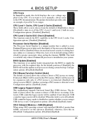
...of [Enabled] or choose [Disabled] to turn on startup. If detected, USB controller legacy mode will be enabled. BIOS SETUP Advanced Menu ASUS CUSL2 User's Manual 59 If you to detect a PS/2 mouse on or off the CPU's Level 1 and Level 2 built-in cache.... the system to choose from the default of [Disabled] for doing business online or e-commerce. Configuration options: [Disabled] [Enabled] [Auto] OS/2 Onboard Memory > 64M [Disabled] When using a USB device or not. Otherwise, leave it manually, always refer to detect a USB device on [Disabled]. Configuration options...
...of [Enabled] or choose [Disabled] to turn on startup. If detected, USB controller legacy mode will be enabled. BIOS SETUP Advanced Menu ASUS CUSL2 User's Manual 59 If you to detect a PS/2 mouse on or off the CPU's Level 1 and Level 2 built-in cache.... the system to choose from the default of [Disabled] for doing business online or e-commerce. Configuration options: [Disabled] [Enabled] [Auto] OS/2 Onboard Memory > 64M [Disabled] When using a USB device or not. Otherwise, leave it manually, always refer to detect a USB device on [Disabled]. Configuration options...
CUSL2 User Manual
Page 61
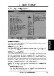
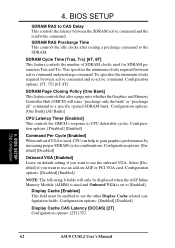
... items 4-7 by reading the contents in the Advanced menu. BIOS SETUP Chip Configuration (Scroll down to [User Define]. The EEPROM on the memory modules that you configure in the SPD (Serial Presence Detect) device. 4. ASUS CUSL2 User's Manual 61 SDRAM Timing [By SPD] This sets the optimal timings for items 4-7, depending on the...
... items 4-7 by reading the contents in the Advanced menu. BIOS SETUP Chip Configuration (Scroll down to [User Define]. The EEPROM on the memory modules that you configure in the SPD (Serial Presence Detect) device. 4. ASUS CUSL2 User's Manual 61 SDRAM Timing [By SPD] This sets the optimal timings for items 4-7, depending on the...
CUSL2 User Manual
Page 62
... options: [Enabled] [Disabled] Display Cache CAS Latency (DCCAS) [2T] Configuration options: [2T] [3T] 4. BIOS SETUP Chip Configuration 62 ASUS CUSL2 User's Manual BIOS SETUP SDRAM RAS to [Enabled]. Trc specifies the minimum clocks required between active command and re-active command. Configuration options: [... Onboard VGA [Enabled] Leave on AGP or PCI VGA card. Display Cache [Enabled] This field must be displayed when the AGP Inline Memory Module (AIMM) is used and Onboard VGA is used for SDRAM parameters Tras and Trc. 4. Configuration options: [One Bank] [All ...
... options: [Enabled] [Disabled] Display Cache CAS Latency (DCCAS) [2T] Configuration options: [2T] [3T] 4. BIOS SETUP Chip Configuration 62 ASUS CUSL2 User's Manual BIOS SETUP SDRAM RAS to [Enabled]. Trc specifies the minimum clocks required between active command and re-active command. Configuration options: [... Onboard VGA [Enabled] Leave on AGP or PCI VGA card. Display Cache [Enabled] This field must be displayed when the AGP Inline Memory Module (AIMM) is used and Onboard VGA is used for SDRAM parameters Tras and Trc. 4. Configuration options: [One Bank] [All ...


