
AT5IONT-I User's manual
Page 1
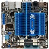
Motherboard AT5IONT-I DELUXE AT5IONT-I
Motherboard AT5IONT-I DELUXE AT5IONT-I
AT5IONT-I User's manual
Page 2
...the problem (please do NOT send large attachments such as required under the Lesser General Public License Version ("LGPL"). IN NO EVENT SHALL ASUS, ITS DIRECTORS, OFFICERS, EMPLOYEES OR AGENTS BE LIABLE FOR ANY INDIRECT, SPECIAL, INCIDENTAL, OR CONSEQUENTIAL DAMAGES (INCLUDING DAMAGES FOR LOSS OF ... and to this information. ASUSTeK is dependent on the preferred carrier and the location where you encounter any language in this product. ASUS PROVIDES THIS MANUAL "AS IS" WITHOUT WARRANTY OF ANY KIND, EITHER EXPRESS OR IMPLIED, INCLUDING BUT NOT LIMITED TO THE IMPLIED...
...the problem (please do NOT send large attachments such as required under the Lesser General Public License Version ("LGPL"). IN NO EVENT SHALL ASUS, ITS DIRECTORS, OFFICERS, EMPLOYEES OR AGENTS BE LIABLE FOR ANY INDIRECT, SPECIAL, INCIDENTAL, OR CONSEQUENTIAL DAMAGES (INCLUDING DAMAGES FOR LOSS OF ... and to this information. ASUSTeK is dependent on the preferred carrier and the location where you encounter any language in this product. ASUS PROVIDES THIS MANUAL "AS IS" WITHOUT WARRANTY OF ANY KIND, EITHER EXPRESS OR IMPLIED, INCLUDING BUT NOT LIMITED TO THE IMPLIED...
AT5IONT-I User's manual
Page 3
Contents Notices...v Safety information vi About this guide vi AT5IONT-I Series specifications summary viii Chapter 1: Product introduction 1.1 Before you proceed 1-1 1.2 Motherboard overview 1-2 1.2.1 Motherboard layout 1-2 1.2.2 Layout contents 1-3 1.3 Central Processing ...Rear panel connectors 1-8 1.7.2 Internal connectors 1-10 1.8 Software support 1-14 1.8.1 Installing an operating system 1-14 1.8.2 Support DVD information 1-14 1.8.3 ASUS VideoSecurity 1-15 1.8.4 ASUS Home Theater Gate 1-17 1.8.5 ASUS @Vibe 1-20 Chapter 2: BIOS information 2.1 Managing and updating your BIOS...
Contents Notices...v Safety information vi About this guide vi AT5IONT-I Series specifications summary viii Chapter 1: Product introduction 1.1 Before you proceed 1-1 1.2 Motherboard overview 1-2 1.2.1 Motherboard layout 1-2 1.2.2 Layout contents 1-3 1.3 Central Processing ...Rear panel connectors 1-8 1.7.2 Internal connectors 1-10 1.8 Software support 1-14 1.8.1 Installing an operating system 1-14 1.8.2 Support DVD information 1-14 1.8.3 ASUS VideoSecurity 1-15 1.8.4 ASUS Home Theater Gate 1-17 1.8.5 ASUS @Vibe 1-20 Chapter 2: BIOS information 2.1 Managing and updating your BIOS...

AT5IONT-I User's manual
Page 4
... APIC Support 2-11 2.5.4 APM Configuration 2-11 2.5.5 Hardware Monitor 2-12 2.6 Boot menu 2-12 2.6.1 Boot Device Priority 2-12 2.6.2 Boot Settings Configuration 2-13 2.6.3 Security 2-13 2.7 Tools menu 2-15 2.7.1 ASUS EZ Flash 2 2-15 2.7.2 Express Gate 2-15 2.8 Exit menu 2-16 iv
... APIC Support 2-11 2.5.4 APM Configuration 2-11 2.5.5 Hardware Monitor 2-12 2.6 Boot menu 2-12 2.6.1 Boot Device Priority 2-12 2.6.2 Boot Settings Configuration 2-13 2.6.3 Security 2-13 2.7 Tools menu 2-15 2.7.1 ASUS EZ Flash 2 2-15 2.7.2 Express Gate 2-15 2.8 Exit menu 2-16 iv
AT5IONT-I User's manual
Page 5
... can be determined by one or more of the crossed out wheeled bin indicates that interference will not occur in our products at ASUS REACH website at http://csr.asus.com/english/REACH.htm. This symbol of the crossed out wheeled bin indicates that to correct the interference by turning the equipment...
... can be determined by one or more of the crossed out wheeled bin indicates that interference will not occur in our products at ASUS REACH website at http://csr.asus.com/english/REACH.htm. This symbol of the crossed out wheeled bin indicates that to correct the interference by turning the equipment...
AT5IONT-I User's manual
Page 6
vi Do not place the product in your local power company. • If the power supply is broken, do not try to fix it by yourself. If you are not sure about the voltage of the electrical outlet you are also provided. If you need when installing and configuring the motherboard. Detailed descriptions of the motherboard and the new technology it , carefully read all power cables from the existing system before you encounter technical problems with the package. • Before using an adapter or extension cord. Contact a qualified service technician or your retailer. About ...
vi Do not place the product in your local power company. • If the power supply is broken, do not try to fix it by yourself. If you are not sure about the voltage of the electrical outlet you are also provided. If you need when installing and configuring the motherboard. Detailed descriptions of the motherboard and the new technology it , carefully read all power cables from the existing system before you encounter technical problems with the package. • Before using an adapter or extension cord. Contact a qualified service technician or your retailer. About ...

AT5IONT-I User's manual
Page 7
...enclosed in this manual. These documents are linked with a plus sign (+). NOTE: Tips and additional information to the ASUS contact information. 2. Refer to help you complete a task. Conventions used throughout this guide To ensure that you must press the enclosed key.... ASUS websites The ASUS website provides updated information on ASUS hardware and software products. Example: means that you must press the Enter or Return key. If you must...
...enclosed in this manual. These documents are linked with a plus sign (+). NOTE: Tips and additional information to the ASUS contact information. 2. Refer to help you complete a task. Conventions used throughout this guide To ensure that you must press the enclosed key.... ASUS websites The ASUS website provides updated information on ASUS hardware and software products. Example: means that you must press the Enter or Return key. If you must...
AT5IONT-I User's manual
Page 8
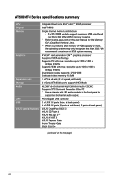
AT5IONT-I Series specifications summary CPU Chipset Memory Graphics Expansion slot Storage Audio LAN USB ASUS special features Integrated Dual-Core Intel® Atom™ D525 processor Intel® NM10 Single channel memory architecture - 2 x SO-DIMM sockets support maximum 4GB unbuffered non-ECC 800 MHz DDR3 memory modules * Refer to www.asus... (blue, at back panel) 4 x USB 2.0 ports (2 ports at mid-board, 2 ports at back panel) ASUS CrashFree BIOS 3 ASUS EZ Flash 2 ASUS MyLogo 2™ ASUS AI NET 2 ASUS Express Gate Home Theater Gate Stack Cool 3+ (continued on the next page) viii
AT5IONT-I Series specifications summary CPU Chipset Memory Graphics Expansion slot Storage Audio LAN USB ASUS special features Integrated Dual-Core Intel® Atom™ D525 processor Intel® NM10 Single channel memory architecture - 2 x SO-DIMM sockets support maximum 4GB unbuffered non-ECC 800 MHz DDR3 memory modules * Refer to www.asus... (blue, at back panel) 4 x USB 2.0 ports (2 ports at mid-board, 2 ports at back panel) ASUS CrashFree BIOS 3 ASUS EZ Flash 2 ASUS MyLogo 2™ ASUS AI NET 2 ASUS Express Gate Home Theater Gate Stack Cool 3+ (continued on the next page) viii
AT5IONT-I User's manual
Page 9
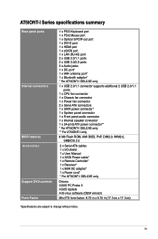
...LAN (RJ-45) port 2 x USB 2.0/1.1 ports 2 x USB 3.0/2.0 ports 3 x Audio jacks 1 x DC port* 1 x WiFi antenna port* 1 x Bluetooth adapter* * For AT5IONT-I DELUXE only 1 x USB 2.0/1.1 connector supports additional 2 USB 2.0/1.1 ports 1 x CPU fan connector 1 x Chassis fan connector 1 x Power fan connector 2 x Serial ATA connectors 1 x...1 x SATA Power cable* 1 x Remote Controller* 1 x Receiver* 1 x 90W DC adapter* 1 x Power cord* * For AT5IONT-I DELUXE only Drivers ASUS PC Probe II ASUS Update Anti-virus software (OEM version) Mini ITX form factor: 6.75 in x 6.75 in (17.1cm x 17.1cm) *Specifications ...
...LAN (RJ-45) port 2 x USB 2.0/1.1 ports 2 x USB 3.0/2.0 ports 3 x Audio jacks 1 x DC port* 1 x WiFi antenna port* 1 x Bluetooth adapter* * For AT5IONT-I DELUXE only 1 x USB 2.0/1.1 connector supports additional 2 USB 2.0/1.1 ports 1 x CPU fan connector 1 x Chassis fan connector 1 x Power fan connector 2 x Serial ATA connectors 1 x...1 x SATA Power cable* 1 x Remote Controller* 1 x Receiver* 1 x 90W DC adapter* 1 x Power cord* * For AT5IONT-I DELUXE only Drivers ASUS PC Probe II ASUS Update Anti-virus software (OEM version) Mini ITX form factor: 6.75 in x 6.75 in (17.1cm x 17.1cm) *Specifications ...
AT5IONT-I User's manual
Page 10
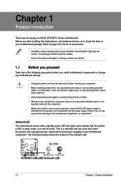
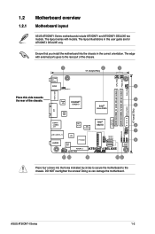
Refer to page ix for buying an ASUS® AT5IONT-I Series motherboard! Onboard LED The motherboard comes with the component. • Before you install or remove any motherboard component. Failure to do so may cause ... following precautions before you install motherboard components or change any motherboard settings. • Unplug the power cord from the power supply. SB_PWR AT5IONT-I DELUXE ON OFF Standby Power Powered Off AT5IONT-I DELUXE two models. This is ON, in sleep mode, or in soft-off or the power cord is detached from the...
Refer to page ix for buying an ASUS® AT5IONT-I Series motherboard! Onboard LED The motherboard comes with the component. • Before you install or remove any motherboard component. Failure to do so may cause ... following precautions before you install motherboard components or change any motherboard settings. • Unplug the power cord from the power supply. SB_PWR AT5IONT-I DELUXE ON OFF Standby Power Powered Off AT5IONT-I DELUXE two models. This is ON, in sleep mode, or in soft-off or the power cord is detached from the...
AT5IONT-I User's manual
Page 11
ASUS AT5IONT-I DELUXE two models. The layout varies with external ports goes to the chassis. The edge with models. Ensure that you install the motherboard into... KBMS 3 PS2_USBPW1-4 Lithium Cell CMOS Power DDR3 SO-DIMM_A1 (64bit, 204-pin module) SPDIFO_HDMI Place this user guide are for AT5IONT-I DELUXE only. 1.2 1.2.1 Motherboard overview Motherboard layout ASUS AT5IONT-I Series motherboards include AT5IONT-I and AT5IONT-I Series 1-2 The layout illustrations in the correct orientation. DO NOT overtighten the screws! Super NVIDIA® 4 I/O ION2010 Intel® 5...
ASUS AT5IONT-I DELUXE two models. The layout varies with external ports goes to the chassis. The edge with models. Ensure that you install the motherboard into... KBMS 3 PS2_USBPW1-4 Lithium Cell CMOS Power DDR3 SO-DIMM_A1 (64bit, 204-pin module) SPDIFO_HDMI Place this user guide are for AT5IONT-I DELUXE only. 1.2 1.2.1 Motherboard overview Motherboard layout ASUS AT5IONT-I Series motherboards include AT5IONT-I and AT5IONT-I Series 1-2 The layout illustrations in the correct orientation. DO NOT overtighten the screws! Super NVIDIA® 4 I/O ION2010 Intel® 5...
AT5IONT-I User's manual
Page 12
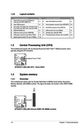
Serial ATA connectors (7-pin SATA1/2) 1-10 4. DDR3 SO-DIMM slots 1-3 11. D525 AT5IONT-I DELUXE AT5IONT-I DELUXE 204-pin DDR3 SO-DIMM sockets 1-3 Chapter 1: Product introduction Keyboard/mouse power and USB device wake-up (3-pin USBPW56) 1-7 12. Internal speaker connector (4-pin ... Double Data Rate 3 (DDR3) Small Outline Dual Inline Memory Modules (SO-DIMM) sockets. The figure illustrates the location of the DDR3 DIMM sockets: DIMM_A1 DIMM_A2 AT5IONT-I DELUXE AT5IONT-I DELUXE CPU -
Serial ATA connectors (7-pin SATA1/2) 1-10 4. DDR3 SO-DIMM slots 1-3 11. D525 AT5IONT-I DELUXE AT5IONT-I DELUXE 204-pin DDR3 SO-DIMM sockets 1-3 Chapter 1: Product introduction Keyboard/mouse power and USB device wake-up (3-pin USBPW56) 1-7 12. Internal speaker connector (4-pin ... Double Data Rate 3 (DDR3) Small Outline Dual Inline Memory Modules (SO-DIMM) sockets. The figure illustrates the location of the DDR3 DIMM sockets: DIMM_A1 DIMM_A2 AT5IONT-I DELUXE AT5IONT-I DELUXE CPU -
AT5IONT-I User's manual
Page 13
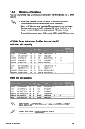
...• • • • • • • DDR3 1333MHz and DDR3 1067MHz memory modules run at www.asus.com for the OS can be about 3GB or less. Size APACER AS01GFA06C7NBGC 1GB HYNIX HMT112S6BFR6C-G7 1GB KINGSTON KVR1066D3S7/1G 1GB KINGSTON ... KTC ELPIDA ELPIDA Chip NO. Timing Voltage AM5D5808AEWSBG 9 - J1108BDBG-DJ-F 9 1.5V J1108BDBG-DJ-F - - AT5IONT-I Series motherboards. H5TQ2G83BFR - - D1288JELDPGD9U - - ASUS AT5IONT-I Series 1-4 1.4.2 Memory configurations You may install 512MB, 1GB, and 2GB unbuffered non‑ECC DDR3 SO-DIMMs...
...• • • • • • • DDR3 1333MHz and DDR3 1067MHz memory modules run at www.asus.com for the OS can be about 3GB or less. Size APACER AS01GFA06C7NBGC 1GB HYNIX HMT112S6BFR6C-G7 1GB KINGSTON KVR1066D3S7/1G 1GB KINGSTON ... KTC ELPIDA ELPIDA Chip NO. Timing Voltage AM5D5808AEWSBG 9 - J1108BDBG-DJ-F 9 1.5V J1108BDBG-DJ-F - - AT5IONT-I Series motherboards. H5TQ2G83BFR - - D1288JELDPGD9U - - ASUS AT5IONT-I Series 1-4 1.4.2 Memory configurations You may install 512MB, 1GB, and 2GB unbuffered non‑ECC DDR3 SO-DIMMs...
AT5IONT-I User's manual
Page 14
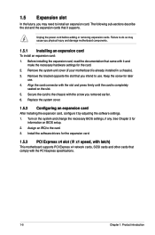
1.5 Expansion slot In the future, you physical injury and damage motherboard components. 1.5.1 Installing an expansion card To install an expansion card: 1. The following sub‑sections describe the slot and the expansion cards that comply with the screw you intend to install an expansion card. Align the card connector with it and make the necessary hardware settings for later use . Keep the screw for the card. 2. See Chapter 2 for the expansion card. 1.5.3 PCI Express x4 slot (@ x1 speed, with latch) This motherboard supports PCI Express x4 network cards, SCSI cards and...
1.5 Expansion slot In the future, you physical injury and damage motherboard components. 1.5.1 Installing an expansion card To install an expansion card: 1. The following sub‑sections describe the slot and the expansion cards that comply with the screw you intend to install an expansion card. Align the card connector with it and make the necessary hardware settings for later use . Keep the screw for the card. 2. See Chapter 2 for the expansion card. 1.5.3 PCI Express x4 slot (@ x1 speed, with latch) This motherboard supports PCI Express x4 network cards, SCSI cards and...
AT5IONT-I User's manual
Page 15
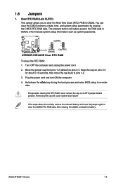
1.6 Jumpers 1. CLRTC 12 23 AT5IONT-I DELUXE Normal (Default) Clear RTC AT5IONT-I Series 1-6 After clearing the CMOS, reinstall the battery. Keep the cap on CLRTC jumper default position. Plug the power cord and turn ON the computer. 4. ... seconds, then move the jumper again to clear the Real Time Clock (RTC) RAM in CMOS, which include system setup information such as system passwords. ASUS AT5IONT-I DELUXE Clear RTC RAM To erase the RTC RAM: 1. You can clear the CMOS memory of date, time, and system setup parameters by erasing the...
1.6 Jumpers 1. CLRTC 12 23 AT5IONT-I DELUXE Normal (Default) Clear RTC AT5IONT-I Series 1-6 After clearing the CMOS, reinstall the battery. Keep the cap on CLRTC jumper default position. Plug the power cord and turn ON the computer. 4. ... seconds, then move the jumper again to clear the Real Time Clock (RTC) RAM in CMOS, which include system setup information such as system passwords. ASUS AT5IONT-I DELUXE Clear RTC RAM To erase the RTC RAM: 1. You can clear the CMOS memory of date, time, and system setup parameters by erasing the...
AT5IONT-I User's manual
Page 16
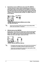
... normal condition or in sleep mode. 1-7 Chapter 1: Product introduction The USBPW1-4 jumper is for each USB port; USBPW56 12 23 AT5IONT-I DELUXE +5V (Default) +5VSB AT5IONT-I DELUXE PS2 Keyboard/Mouse power setting and USB device wake-up from S1 sleep mode (CPU stopped, DRAM refreshed, system running in... sleep mode. 3. PS2_USBPW1-4 12 23 +5V +5VSB (Default) AT5IONT-I DELUXE AT5IONT-I DELUXE USB Device Wake-up • The USB device wake-up the computer from S3 and S4 sleep modes (no power to wake up...
... normal condition or in sleep mode. 1-7 Chapter 1: Product introduction The USBPW1-4 jumper is for each USB port; USBPW56 12 23 AT5IONT-I DELUXE +5V (Default) +5VSB AT5IONT-I DELUXE PS2 Keyboard/Mouse power setting and USB device wake-up from S1 sleep mode (CPU stopped, DRAM refreshed, system running in... sleep mode. 3. PS2_USBPW1-4 12 23 +5V +5VSB (Default) AT5IONT-I DELUXE AT5IONT-I DELUXE USB Device Wake-up • The USB device wake-up the computer from S3 and S4 sleep modes (no power to wake up...
AT5IONT-I User's manual
Page 17
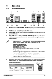
... Bluetooth functions, download the latest Bluetooth driver from the ASUS support wedsite at http://support.asus.com. • Bluetooth Electrical Specification: Bluetooth specification V.2.1 compliant; Switch on the Support DVD's Drivers screen, follow the steps below for AT5IONT-I Series 1-8 Refer to the table below : 1....SPEED LED Status OFF ORANGE GREEN Description 10 Mbps connection 100 Mbps connection 1 Gbps connection ACT/LINK SPEED LED LED LAN port ASUS AT5IONT-I DELUXE only). PS/2 Mouse port (green). Shut down your computer and switch off the Power Supply Unit (PSU). 2....
... Bluetooth functions, download the latest Bluetooth driver from the ASUS support wedsite at http://support.asus.com. • Bluetooth Electrical Specification: Bluetooth specification V.2.1 compliant; Switch on the Support DVD's Drivers screen, follow the steps below for AT5IONT-I Series 1-8 Refer to the table below : 1....SPEED LED Status OFF ORANGE GREEN Description 10 Mbps connection 100 Mbps connection 1 Gbps connection ACT/LINK SPEED LED LED LAN port ASUS AT5IONT-I DELUXE only). PS/2 Mouse port (green). Shut down your computer and switch off the Power Supply Unit (PSU). 2....
AT5IONT-I User's manual
Page 18
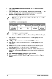
... Bass/Center Side Speaker Out To configure an 8-channel audio output: Use a chassis with HD audio module in 2, 4, 6, or 8-channel configuration. This port is for AT5IONT-I DELUXE only). This port connects to support 8-channel audio output. 9. In the 4, 6, and 8-channel configurations, the function of HD DVD, Blu-ray, and other protected...
... Bass/Center Side Speaker Out To configure an 8-channel audio output: Use a chassis with HD audio module in 2, 4, 6, or 8-channel configuration. This port is for AT5IONT-I DELUXE only). This port connects to support 8-channel audio output. 9. In the 4, 6, and 8-channel configurations, the function of HD DVD, Blu-ray, and other protected...
AT5IONT-I User's manual
Page 19
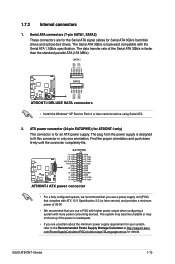
... orientation. Serial ATA connectors (7-pin SATA1, SATA2) These connectors are uncertain about the minimum power supply requirement for details. ASUS AT5IONT-I DELUXE SATA connectors • Install the Windows® XP Service Pack 2 or later versions before using Serial ATA. ...2. GND RSATA_TXP2 RSATA_TXN2 GND RSATA_RXP2 RSATA_RXN2 GND AT5IONT-I AT5IONT-I only) This connector is designed to the Recommended Power Supply Wattage Calculator at http://support.asus. SATA1 SATA2 AT5IONT-I DELUXE AT5IONT-I Series 1-10 Find the proper orientation and push down firmly until...
... orientation. Serial ATA connectors (7-pin SATA1, SATA2) These connectors are uncertain about the minimum power supply requirement for details. ASUS AT5IONT-I DELUXE SATA connectors • Install the Windows® XP Service Pack 2 or later versions before using Serial ATA. ...2. GND RSATA_TXP2 RSATA_TXN2 GND RSATA_RXP2 RSATA_RXN2 GND AT5IONT-I AT5IONT-I only) This connector is designed to the Recommended Power Supply Wattage Calculator at http://support.asus. SATA1 SATA2 AT5IONT-I DELUXE AT5IONT-I Series 1-10 Find the proper orientation and push down firmly until...
AT5IONT-I User's manual
Page 20
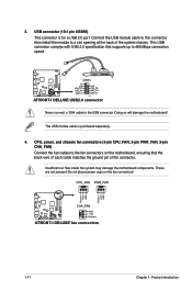
USB56 AT5IONT-I DELUXE PIN 1 AT5IONT-I DELUXE fan connectors 1-11 Chapter 1: Product introduction Insufficient air flow inside the system may damage the motherboard components. These are not jumpers! USB connector (10-1 ... motherboard, ensuring that supports up to a slot opening at the back of the connector. CPU_FAN PWR_FAN Rotation +12V GND Rotation +12V GND CHA_FAN AT5IONT-I DELUXE GND +12V Rotation AT5IONT-I DELUXE USB2.0 connector Never connect a 1394 cable to the fan connectors on the fan connectors! This USB connector complys with USB 2.0 specification that...
USB56 AT5IONT-I DELUXE PIN 1 AT5IONT-I DELUXE fan connectors 1-11 Chapter 1: Product introduction Insufficient air flow inside the system may damage the motherboard components. These are not jumpers! USB connector (10-1 ... motherboard, ensuring that supports up to a slot opening at the back of the connector. CPU_FAN PWR_FAN Rotation +12V GND Rotation +12V GND CHA_FAN AT5IONT-I DELUXE GND +12V Rotation AT5IONT-I DELUXE USB2.0 connector Never connect a 1394 cable to the fan connectors on the fan connectors! This USB connector complys with USB 2.0 specification that...
